


Aluminum electrolytic capacitors
Alu-X product lines
Single-ended capacitors
Series/Type: B43081
Data Sheet
Date: August 2008
© EPCOS AG 2008. Reproduction, publication and dissemination of this publication and the infor-
mation contained therein without EPCOS’ prior express consent is prohibited.
Single-ended capacitors B43081
High ripple current – 105 °C
Single-ended capacitors B43081
High ripple current – 105 °C
Long-life grade capacitors for professional applications
Applications
■ Electronic ballast applications
Features
■ RoHS-compatible
■ Very high ripple current
■ High reliability
■ Load life of 3000 h at 105 °C
Construction
■ Radial leads
■ Aluminum case, fully insulated
■ Charge-discharge proof
■ Minus pole marking on the insulating sleeve
■ Case with safety vent from diameter 8 mm
Delivery mode
■ Bulk
■ Taped, Ammo pack
■ Cut
■ Kinked
Please read Cautions and warnings and
Important notes at the end of this document.
2 08/08
Single-ended capacitors B43081
High ripple current – 105 °C
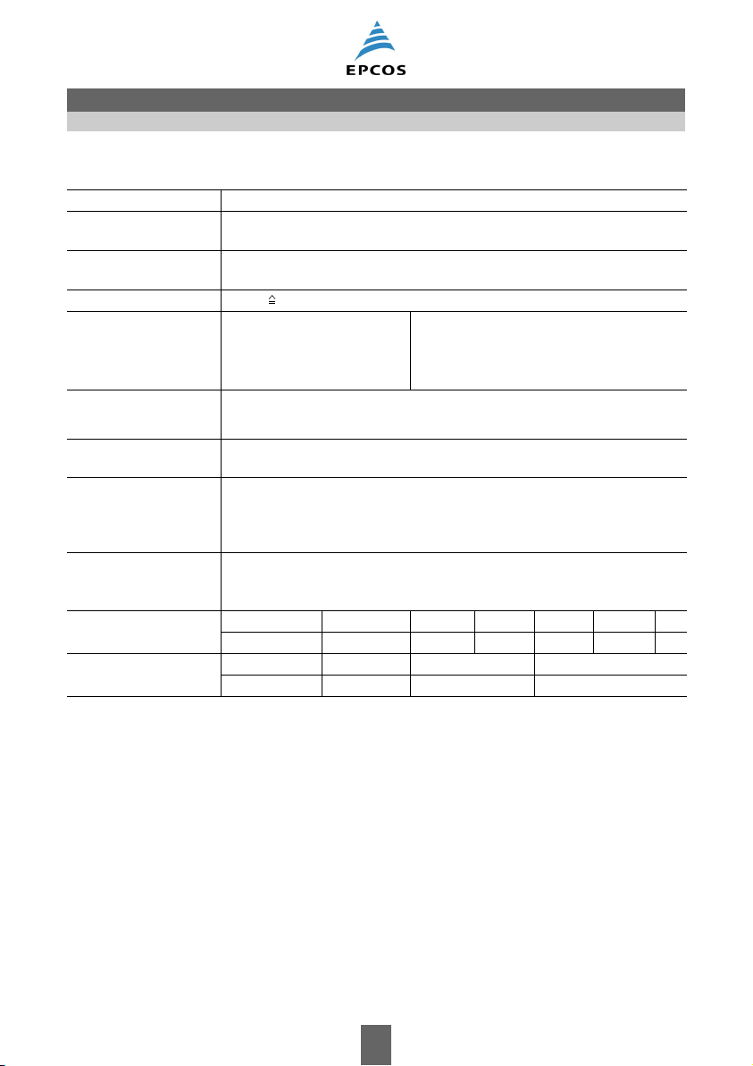
Specifications and characteristics in brief
Rated voltage V
R
Operating temperature
160 ... 400 V DC
–25 °C … +105 °C
range
Rated capacitance C
0.1 … 100 µF
R
(20 °C, 120 Hz)
Capacitance tolerance ±20% M
Load life
(105 °C, V
, I
R
AC,R
Leakage current I
(20 °C, after 5 minutes)
Dissipation factor (max.)
3000 h Requirements:
)
V
leak
I
leak
0.02 µA
C
R
R
⎛⎞
-------
-------
⋅
⋅≤
⎝⎠
µF
V
tan δ ≤ 0.12
∆C/C ≤ ±20% of initial value
tan δ≤ 2 times initial specified limit
I
≤ initial specified limit
leak
(20 °C, 120 Hz)
Low temperature
stability
(impedance ratio)
Z25 °C–()
--------------------------Z +20 °C()
≤ 7
(120 Hz)
Shelf life After storage for 1000 h at 105 °C, the capacitors shall meet the require-
ment of load life test after reforming process. After test: V
to be applied
R
for 30 minutes, 24 to 48 hours before measurement.
Frequency multiplier for
rated ripple current
Temperature multiplier
for rated ripple current
50 Hz 120 Hz 300 Hz 1 kHz 10 kHz 100 kHz
0.3 0.5 0.6 0.8 0.9 1.0
+50 °C +70 °C +85 °C +105 °C
2.1 1.8 1.4 1.0
Please read Cautions and warnings and
Important notes at the end of this document.
3 08/08
Single-ended capacitors B43081
High ripple current – 105 °C
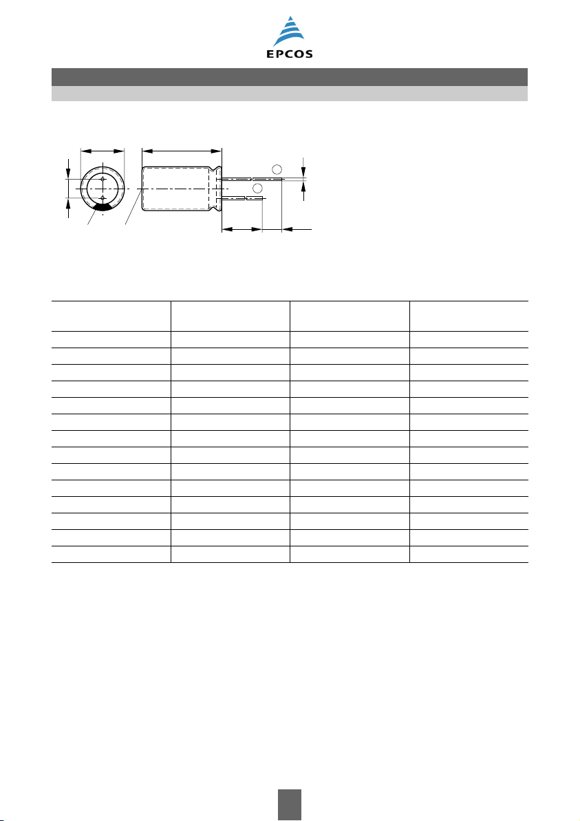
Dimensional drawing
d
a
Minus pole Safety vent
marking
l
+
øb
-
15 min.
5 min.
KAL1080-C-E
Safety vent for diameter ≥ 8 mm.
Case dimensions
d × l
mm
d
max
mm
× I
max
a
mm
6.3 × 11 6.8 × 12.5 2.5 ±0.5 0.5 ±0.1
8 × 11.5 8.5 × 13.0 3.5 ±0.5 0.6 ±0.1
8 × 15 8.5 × 16.5 3.5 ±0.5 0.6 ±0.1
8 × 20 8.5 × 21.5 3.5 ±0.5 0.6 ±0.1
10 × 16 11.0 × 17.5 5.0 ±0.5 0.6 ±0.1
10 × 20 11.0 × 22.0 5.0 ±0.5 0.6 ±0.1
12.5 × 20 13.5 × 22.0 5.0 ±0.5 0.6 ±0.1
12.5 × 25 13.5 × 27.0 5.0 ±0.5 0.6 ±0.1
16 × 20 17.0 × 22.0 7.5 ±0.5 0.8 ±0.1
16 × 25 17.0 × 27.0 7.5 ±0.5 0.8 ±0.1
16 × 31.5 17.0 × 33.5 7.5 ±
0.5 0.8 ±0.1
18 × 20 19.0 × 22.0 7.5 ±0.5 0.8 ±0.1
18 × 25 19.0 × 27.0 7.5 ±0.5 0.8 ±0.1
18 × 31.5 19.0 × 33.5 7.5 ±0.5 0.8 ±0.1
b
mm
Please read Cautions and warnings and
Important notes at the end of this document.
4 08/08
Single-ended capacitors B43081
High ripple current – 105 °C
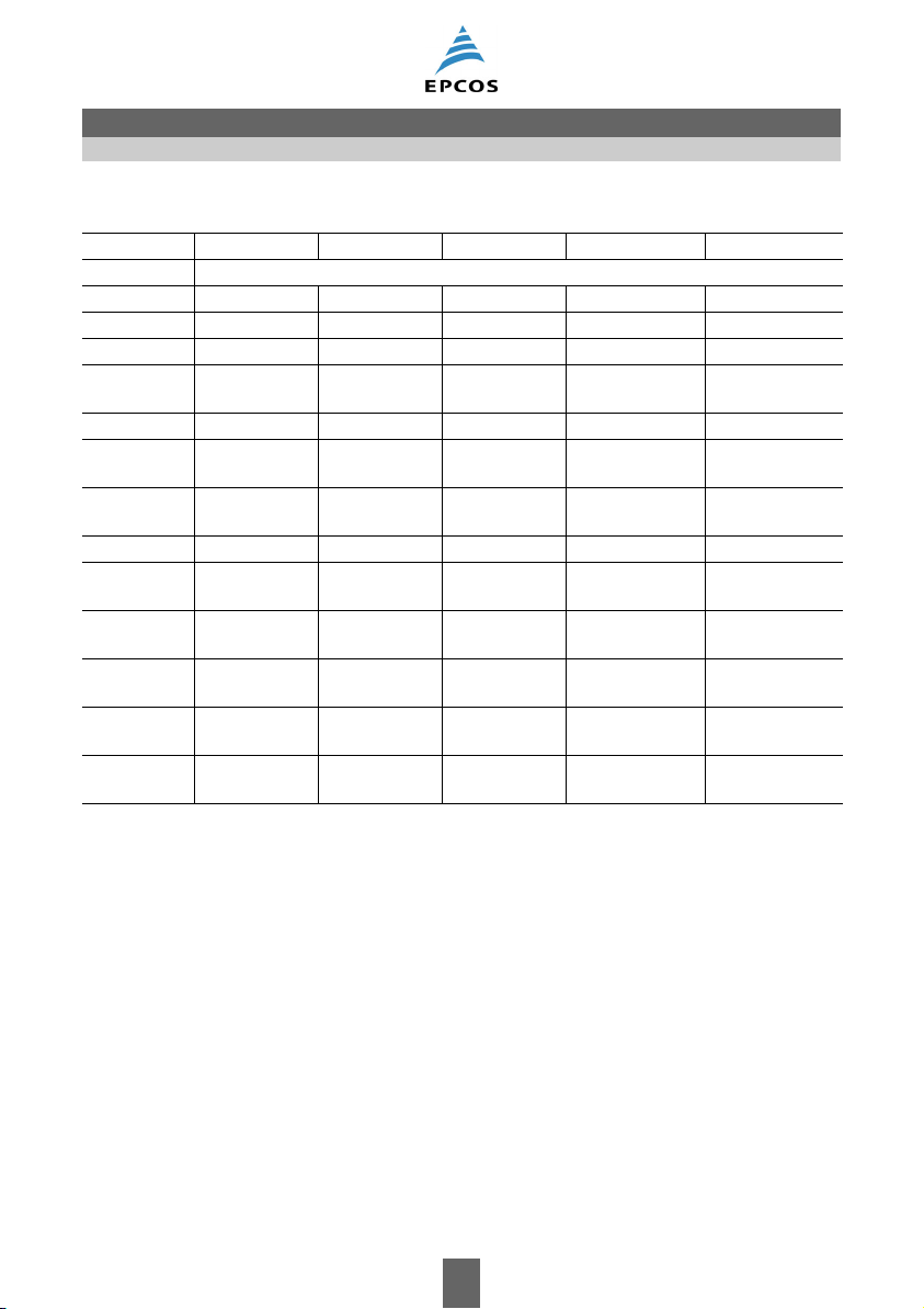
Overview of available types
VR (V DC) 160 200 250 350 400
Case dimensions d × l (mm)
(µF)
C
R
1.0 8 × 11.5 6.3 × 11.5
2.2 8 × 15
3.3 8 × 15
8 × 20
4.7 8 × 11.5 10 × 16 10 × 20
6.8 10 × 16 10 × 16 10 × 20
12.5 × 20
10 10 × 16 10 × 16 10 × 20 10 × 20
12.5 × 20
15 10 × 20 10 × 16 16 × 25
22 10 × 20 10 × 20 10 × 20
12.5 × 20
33 10 × 20 12.5 × 20 12.5 × 20
12.5 × 25
47 12.5 × 20
12.5 × 25
68 12.5 × 25 12.5 × 25
100 16 × 25 16 × 25
12.5 × 20 12.5 × 25
16
16 × 25
16 × 20
18 × 35.5
18 × 25
× 25
12.5 × 20 12.5 × 25
16 × 25
16 × 20 16 × 25
16 × 31.5
16 × 25 16 × 35.5
18 × 25
18 × 25
18 × 20
Please read Cautions and warnings and
Important notes at the end of this document.
5 08/08

Single-ended capacitors B43081
High ripple current – 105 °C
Technical data and ordering codes
V
R
V DC
C
R
120 Hz
20 °C
µF
Case
dimensions
d × l
mm
I
AC,R
100 kHz
105 °C
mA
Ordering code
(composition see
below)
160 22 10 × 20 500 B43081A1226M***
33 10 × 20 500 B43081A1336M***
47 12.5 × 20 600 B43081A1476M***
47 12.5 × 25 670 B43081B1476M***
68 12.5 × 25 750 B43081A1686M***
100 16 × 25 1100 B43081A1107M***
200 4.7 8 × 11.5 158 B43081A2475M***
6.8 10 × 16 230 B43081A2685M***
10 10 × 16 310 B43081A2106M***
15 10 × 20 400 B43081A2156M***
22 10 × 20 500 B43081A2226M***
33 12.5 × 20 600 B43081A2336M***
47 12.5 × 20 600 B43081A2476M***
68 12.5 × 25 750 B43081A2686M***
68 16 × 20 750 B43081B2686M***
100 16 × 25 1100 B43081A2107M***
100 18 × 20 1100 B43081B2107M***
250 1.0 8 × 11.5 18 B43081F2105M***
4.7 10 × 16 200 B43081F2475M***
6.8 10 × 16 240 B43081F2685M***
10 10 × 16 300 B43081F2106M***
15 10 × 16 380 B43081F2156M***
22 10 × 20 500 B43081F2226M***
22 12.5 × 20 600 B43081G2226M***
33 12.5 × 20 600 B43081F2336M***
33 12.5 × 25 670 B43081G2336M***
47 12.5 × 25 700 B43081F2476M***
47 16 × 25 780 B43081G2476M***
68 16 × 25 1000 B43081F2686M***
68 18 × 35.5 1200 B43081G2686M***
100 18 × 25 1200 B43081F2107M***
350 10 10 × 20 250 B43081A4106M***
22 12.5 × 20 350 B43081A4226M***
33 16 × 20 500 B43081A4336M***
47 16 × 25 650 B43081A4476M***
68 18 × 25 800 B43081A4686M***
*** = Version
000 = for standard leads, bulk
001 = for kinked leads, bulk
002 = for cut leads, bulk
007 = for taped leads, Ammo pack, lead spacing a = 2.5 mm
006 = for taped leads, Ammo pack, lead spacing a = 3.5 mm
008 = for taped leads, Ammo pack, lead spacing a = 5.0 mm
Please read Cautions and warnings and
Important notes at the end of this document.
6 08/08

Single-ended capacitors B43081
High ripple current – 105 °C
Technical data and ordering codes
V
R
V DC
C
R
120 Hz
20 °C
µF
Case
dimensions
d × l
mm
I
AC,R
100 kHz
105 °C
mA
Ordering code
(composition see
below)
400 1.0 6.3 × 11.5 18 B43081A9105M***
2.2 8 × 15 108 B43081A9225M***
3.3 8 × 15 108 B43081A9335M***
3.3 8 × 20 121 B43081B9335M***
4.7 10 × 20 180 B43081A9475M***
6.8 10 × 20 220 B43081A9685M***
6.8 12.5 × 20 240 B43081B9685M***
10 10 × 20 250 B43081A9106M***
10 12.5 × 20 270 B43081B9106M***
15 16 × 25 400 B43081A9156M***
22 12.5 × 25 400 B43081A9226M***
22 16 × 25 500 B43081B9226M***
33 16 × 25 600 B43081A9336M***
33 16 × 31.5 670 B43081B9336M***
47 16 × 35.5 750 B43081A9476M***
47 18 × 25 750 B43081B9476M***
*** = Version
000 = for standard leads, bulk
001 = for kinked leads, bulk
002 = for cut leads, bulk
007 = for taped leads, Ammo pack, lead spacing a = 2.5 mm
006 = for taped leads, Ammo pack, lead spacing a = 3.5 mm
008 = for taped leads, Ammo pack, lead spacing a = 5.0 mm
Please read Cautions and warnings and
Important notes at the end of this document.
7 08/08

Single-ended capacitors B43081
Single-ended capacitors B43081
Taping, packing and lead configurations
Taping, packing and lead configurations
Taping, packing and lead configurations of single-ended capacitors
Single-ended capacitors are available taped in Ammo pack from diameter 4 to 10 mm as follows:
Lead spacing 2.0 mm (∅ d = 4 ... 5 mm)
Last 3 digits of ordering code: 016
ød
P
P
0
h∆h ∆
D
2
0
H
H
0
W
1
W
0
W
W
1 max.
View B
t
1
Base tape
Adhesive tape
F
P
B
1
l
KAL1138-D-E
Dimensions in mm
∅ dF H W W
0
W1W2PP0P1l
t ∆hD
1
4 ... 5 2.0 18.5 18.0 7.0 9.0 3.0 12.7 12.7 5.10 1.0 0.7 1 4.0
–0.2 ±0.75 ±0.5 min. ±0.5 max. ±1.0 ± 0.3 ±0.7 max. ±0.2 ±1.0 ±0.2
0
Please read Cautions and warnings and
Important notes at the end of this document.
8 08/08

Single-ended capacitors B43081
Taping, packing and lead configurations
Lead spacing 2.5 mm (∅ d = 4 ... 6.3 mm)
Last 3 digits of ordering code: 007
ød
P
P
0
h∆h ∆
0
H
H
Base tape
Adhesive tape
2
W
1
0
W
W
W
F
P
1
D
0
1
B
l
1 max.
View B
t
KAL1074-3-E
Dimensions in mm
∅ dFHH
WW0W1W2PP0P1l
0
t ∆hD
1
0
4 ... 6.3 2.5 18.5 16.0 18.0 7.0 9.0 3.0 12.7 12.7 5.10 1.0 0.7 0 4.0
To le r a nc e – 0 . 2 ±0.75 ±0.5 ±0.5 min. ±0.5 max. ±1.0 ±0.3 ±0.7 max. ±0.2 ±1.0 ±0.2
Lead spacing 3.5 mm (∅ d = 8 mm)
Last 3 digits of ordering code: 006
ød
P
P
0
D
2
0
H
H
0
W
1
W
0
W
W
h∆h ∆
1 max.
View B
t
1
Base tape
Adhesive tape
F
P
B
1
l
KAL1138-D-E
Dimensions in mm
∅ dFHWW
0W1W2
PP0P1l
t ∆hD
1
0
8 3.5 18.5 18.0 10 9.0 3.0 12.7 12.7 5.10 1.0 0.7 1 4.0
To le r a nc e ±0.5 ±0.75 ±0.5 min. ±0.5 max. ±1.0 ± 0.3 ± 0.7 max. ±0.2 max. ±0.2
Please read Cautions and warnings and
Important notes at the end of this document.
9 08/08

Single-ended capacitors B43081
Taping, packing and lead configurations
Lead spacing 5.0 mm (∅ d = 4 ... 8 mm)
Last 3 digits of ordering code: 008
ød
P
P
0
h∆ h∆
2
H
0
H
W
1
W
0
W
W
1 max.
View B
t
Base tape
Adhesive tape
F
P
1
D
0
B
1
l
KAL1075-B-E
Lead spacing 5.0 mm (∅ d = 10 mm)
Last 3 digits of ordering code: 008
ød
P
P
0
2
H
W
0
W
1
W
h∆ h∆
1 max.
View B
W
t
Base tape
Adhesive tape
F
P
1
D
0
B
1
l
KAL1076-J-E
Dimensions in mm
∅ dFHH
WW0W1W2PP0P1L1t ∆hD
0
0
4 ... 6.3 5.0 18.5 16 18.0 7.0 9.0 3.0 12.7 12.7 3.85 1.0 0.6 2.0 4.0
8 5.0 18.5 16 18.0 10 9.0 3.0 12.7 12.7 3.85 1.0 0.6 2.0 4.0
10 5.0 18.5 – 18.0 12.5 9.0 3.0 12.7 12.7 3.85 1.0 0.6 2.0 4.0
Tolerance +0.6
±0.75 ±0.5 +1.0
–0.2
+1.0–0±0.5 max. ±0.5 ±0.3 ± 0.7 max. +0.3
–0.5
max. ±0.2
–0.2
Taping is available up to dimensions d × l = 10 × 20 mm. For ∅ 12.5, 16 and 18 mm taping is not
available.
Please read Cautions and warnings and
Important notes at the end of this document.
10 08/08

Single-ended capacitors B43081
Taping, packing and lead configurations
Kinked or cut leads
Single-ended capacitors are available with kinked or cut leads. Other lead configurations also available on request.
Kinked leads
Last 3 digits of ordering code: 001
3.2±0.1
l
2.1±0.1
1.2±0.1
KAL1137-5
l
ød
ød
4.5±0.5
a
KAL1084-A
Case size d × l (mm) a (mm) Case size d × l (mm) a (mm)
4 × 7 1.5 12.5 × 16 5.0
5 × 7 2.0 12.5 × 20 5.0
5 × 11 2.0 12.5 × 25 5.0
6.3 × 7 2.5 12.5 × 31.5 5.0
6.3 × 11 2.5 12.5 × 35.5 5.0
6.3 × 15 2.5 12.5 × 40 5.0
8 × 7 3.5 16 × 20 7.5
8 × 11.5 3.5 16 × 25 7.5
8 × 15 3.5 16 × 31.5 7.5
8 × 20 3.5 16 × 35.5 7.5
10 × 12.5 5.0 16 × 40 7.5
10 × 16 5.0 18 × 20 7.5
10 × 20 5.0 18 × 25 7.5
10 × 25 5.0 18 × 31.5 7.5
10 × 31.5 5.0 18 × 35.5 7.5
18 × 40 7.5
Please read Cautions and warnings and
Important notes at the end of this document.
11 08/08

Single-ended capacitors B43081
Taping, packing and lead configurations
Cut leads
Last 3 digits of ordering code: 002
l
ød
4.5±0.5
a
KAL1086-R
Case size d × l (mm) a (mm) Case size d × l (mm) a (mm)
4 × 7 1.5 12.5 × 16 5.0
5 × 7 2.0 12.5 × 20 5.0
5 × 11 2.0 12.5 × 25 5.0
6.3 × 7 2.5 12.5 × 31.5 5.0
6.3 × 11 2.5 12.5 × 35.5 5.0
6.3 × 15 2.5 12.5 × 40 5.0
8 × 7 3.5 16 × 20 7.5
8 × 11.5 3.5 16 × 25 7.5
8 × 15 3.5 16 × 31.5 7.5
8 × 20 5.0 16 × 35.5 7.5
10 × 12.5 5.0 16 × 40 7.5
10 × 16 5.0 18 × 20 7.5
10 × 20 5.0 18 × 25 7.5
10 × 25 5.0 18 × 31.5 7.5
10 × 31.5 5.0 18 × 35.5 7.5
18 × 40 7.5
Please read Cautions and warnings and
Important notes at the end of this document.
12 08/08

Cautions and warnings
General
Also see “Important notes” on page 15.
1 Aluminum electrolytic capacitors have a bi-polar structure. This is marked on the body of the
capacitor. A capacitor must not be mounted with reversed polarity. The application of an AC
or reverse voltage may cause a short circuit or damage the capacitor. Bi-polar capacitors
must not be used in AC applications, where the polarity may be reversed in the circuits or is
unknown.
2 The DC voltage applied to the capacitor terminal must not exceed its rated operating voltage,
as this will result in a rapid increase of the leakage current and may damage the capacitor. It
is recommended to operate the capacitor at 70–80% of its rated voltage to optimize its service life.
3 The ripple current applied to the capacitor must be within the permitted range. An excessive
ripple current leads to impaired electrical properties and may damage the capacitor. Note that
the sum of the peak values of the ripple voltage and the DC operating voltage must not exceed the rated DC voltage.
4 Capacitors must be used within their permitted range of operating temperature. Operation at
room temperature optimizes their service life.
5 Capacitors with case diameter ≥8 mm are equipped with a safety vent. In capacitors fitted
with a lead or soldering lug, the safety vent is usually located at the base of the case. It needs
sufficient space around it to operate optimally. The following dimensions are recommended:
for case diameter d = 8 to 16 mm, more than 2 mm; for d =18 to 35 mm, more than 3 mm;
and for d = 42 mm or more, more than 5 mm.
6 Capacitors should not be mounted with the safety vent face down on the board. Do not locate
any wire or copper trace near the safety vent. Do not reverse the voltage, as this may result
in excess pressure and the leakage of electrolyte.
7 Gas is released through the safety vent when the pressure inside the capacitor is too high. A
gaseous liquid around the safety vent does not indicate a leakage of electrolyte.
8 The capacitor should be stored under conditions of normal temperature and in a non-acid,
non-alkali environment of normal humidity. Exposure to high temperatures, for example under direct sunlight, will reduce its operating life. If the capacitor is stored in an environment
containing acids or alkalis, the solderability of the leads may be affected.
9 The leakage current of an aluminum electrolytic capacitor may increase after a long period
of storage. After such storage, the capacitor must be aged by applying the rated operating
voltage for 6–8 hours before use.
10 Manual soldering:
a Soldering must be performed within the specified conditions.
Bit temperature: 350 °C; application time of soldering iron: 3 seconds.
b Ensure that the soldering iron does not touch any part of the capacitor body.
Please read Cautions and warnings and
Important notes at the end of this document.
13 08/08

Cautions and warnings
11 Do not apply excessive force to the leads and terminals. Do not move the capacitor after sol-
dering it onto the PC board and do not carry the PC board by gripping the capacitor. Observe
the following rules to prevent undue stress to the capacitor:
a Do not tilt or bend the capacitor after soldering.
b Ensure that the terminal spacing matches the corresponding hole spacing on the PC
board.
12 The aluminum case is not insulated from the cathode. Do not place a conductor under the
aluminum capacitors on the PC board as this may cause a short circuit. The case and top of
capacitors used in switched mode power supplies have a high-voltage-resistant heat shrink
sleeve to ensure safe usage.
13 The leads of capacitors with a case diameter exceeding 14 mm cannot be used for fixing.
Please read Cautions and warnings and
Important notes at the end of this document.
14 08/08

Important notes
Important notes
The following applies to all products named in this publication:
1. Some parts of this publication contain statements about the suitability of our products for
certain areas of application. These statements are based on our knowledge of typical
requirements that are often placed on our products in the areas of application concerned. We
nevertheless expressly point out that such statements cannot be regarded as binding
statements about the suitability of our products for a particular customer application. As
a rule, EPCOS is either unfamiliar with individual customer applications or less familiar with them
than the customers themselves. For these reasons, it is always ultimately incumbent on the
customer to check and decide whether an EPCOS product with the properties described in the
product specification is suitable for use in a particular customer application.
2. We also point out that in individual cases, a malfunction of electronic components or failure
before the end of their usual service life cannot be completely ruled out in the current state
of the art, even if they are operated as specified. In customer applications requiring a very
high level of operational safety and especially in customer applications in which the malfunction
or failure of an electronic component could endanger human life or health (e.g. in accident
prevention or life-saving systems), it must therefore be ensured by means of suitable design of
the customer application or other action taken by the customer (e.g. installation of protective
circuitry or redundancy) that no injury or damage is sustained by third parties in the event of
malfunction or failure of an electronic component.
3. The warnings, cautions and product-specific notes must be observed.
4. In order to satisfy certain technical requirements, some of the products described in this
publication may contain substances subject to restrictions in certain jurisdictions (e.g.
because they are classed as hazardous). Useful information on this will be found in our
Material Data Sheets on the Internet (www.epcos.com/material). Should you have any more
detailed questions, please contact our sales offices.
5. We constantly strive to improve our products. Consequently, the products described in this
publication may change from time to time. The same is true of the corresponding product
specifications. Please check therefore to what extent product descriptions and specifications
contained in this publication are still applicable before or when you place an order.
We also reserve the right to discontinue production and d elivery of products. Consequently,
we cannot guarantee that all products named in this publication will always be available. The
aforementioned does not apply in case of individual agreements deviating from the foregoing for
customer-specific products.
6. Unless otherwise agreed in individual contracts, all orders are subject to the current version
of the “General Terms of Delivery for Products and Services in the Electrical Industry”
published by the German Electrical and Electronics Industry Association (ZVEI).
7. The trade names EPCOS, BAOKE, Alu-X, CeraDiode, CSSP, CTVS, DSSP, MiniBlue, MKK,
MLSC, MotorCap, PCC, PhaseCap, PhaseMod, SIFERRIT, SIFI, SIKOREL, SilverCap,
SIMDAD, SIMID, SineFormer, SIOV, SIP5D, SIP5K, ThermoFuse, WindCap are trademarks
registered or pending in Europe and in other countries. Further information will be found on
the Internet at www.epcos.com/trademarks.
15 08/08
 Loading...