


Aluminum electrolytic capacitors
Axial-lead and soldering star capacitors
Series/Type: B41692, B41792
Date: December 2006
EPCOS AG 2007. Reproduction, publication and dissemination of this publication, enclosures hereto and the
information contained therein without EPCOS' prior express consent is prohibited.
Axial-lead and soldering star capacitors B41692, B41792
Long useful life, compact up to 140 °C
Applications
Compact design for automotive applications up to 150 °C
Features
Up to 150 °C operating temperature at reduced voltage
applied
Long useful life, 2000 h at up to 140 °C
Very high ripple current capability
Compact design
High vibration resistance
Shelf life up to 15 years at storage temperatures up to 40 °C.
To ensure solderability, the capacitors should be built into the
application within one year of delivery. After a total of two
years' storage, the operating voltage must be applied for one
hour to ensure the specified leakage current.
Construction
Charge/discharge-proof, polar
Aluminum case with insulating sleeve
Negative pole connected to case
Terminals
Axial leads, welded to ensure perfect electrical contact
Also available with soldering stars
Taping and packing
Axial-lead capacitors will be delivered in pallet package.
Capacitors with d × l ≤ 16 × 30 mm are also available taped
on reel.
Soldering star capacitors are packed in cardboard.
Important notes at the end of this document.
Page 2 of 16Please read Cautions and warnings and
Long useful life, compact up to 140 °C
Specifications and characteristics in brief
B41692, B41792
Rated voltage V
Surge voltage V
R
S
25 ... 63 V DC
1.15 V
R
Rated capacitance CR220 ... 6800 µF
Capacitance tolerance 10/+30% Q
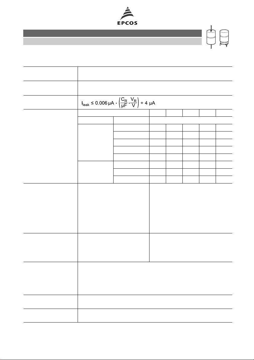
Leakage current I
leak
(5 min, 20 °C)
Self-inductance ESL
1)
Diameter d (mm) 12 14 16 18 20/21
Terminals Length l (mm) Approx. ESL (nH)
axial 25 22 26
29 38
30 21 24 29 34
39 33 38 45
49 50
soldering star 25 6 7
30 6 7 8 10
39 9 11
Useful life Requirements:
AC, R
*)
> 2000 h ∆C/C ≤ ±30% of initial value
AC,R
> 2000 h ESR ≤3 times initial specified limit
AC,R
> 5000 h I
≤ initial specified limit
leak
> 15000 h
> 500000 h
150 °C, Vop, 0.5 I
140 °C, VR, 0.6 I
125 °C, VR, I
85 °C, VR,I
AC, R
AC, max
40 °C, VR, 2 I
*)
Vop:see useful life graph
Voltage endurance test Post test requirements:
125 °C, V
R
2000 h ∆C/C ≤ ±10% of initial value
ESR ≤1.3% initial specified limit
I
≤ initial specified limit
leak
Vibration resistance test To IEC 60068-2-6, test Fc:
Displacement amplitude 1.5 mm, at 10 Hz ... 2 kHz,
acceleration max. 20 g, duration 3 × 2 h.
Capacitor mounted by its wire leads at a distance of (6 ±1) mm from
the case and additionally clamped by the case.
IEC climatic category To IEC 60068-1:
55/125/56 (55 °C/+125 °C/56 days damp heat test)
Detail specification
Sectional specification
Similar to CECC 30301-802
IEC 60384-4
1) If optimum circuit design is used, the values are lower by 30%.
Important notes at the end of this document.
Page 3 of 16Please read Cautions and warnings and
B41692, B41792
Long useful life, compact up to 140 °C
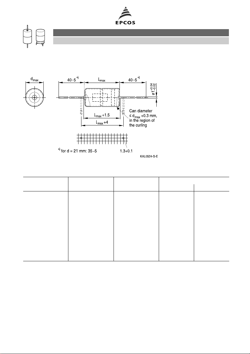
Axial-lead capacitors
Dimensional drawing
Dimensions, weights and packing units
d × l d
max
× I
max
Approx. weight Packing units (pcs.)
mm mm g Pallet Reel
12 × 30 12.5 × 30.5 5.1 288 450
14 × 25 14.5 × 25.5 5.7 200 350
14 × 30 14.5 × 30.5 6.8 200 350
16 × 30 16.5 × 30.5 8.9 180 250
16 × 39 16.5 × 40 11.7 180
18 × 30 18.5 × 30.5 11.1 160
18 × 39 18.5 × 40 14.7 160
20 × 29 20.5 × 29.5 13.5 140
21 × 39 21.5 × 40 20.0 140
21 × 49 21.5 × 50 25.0 110
Important notes at the end of this document.
Page 4 of 16Please read Cautions and warnings and
Long useful life, compact up to 140 °C
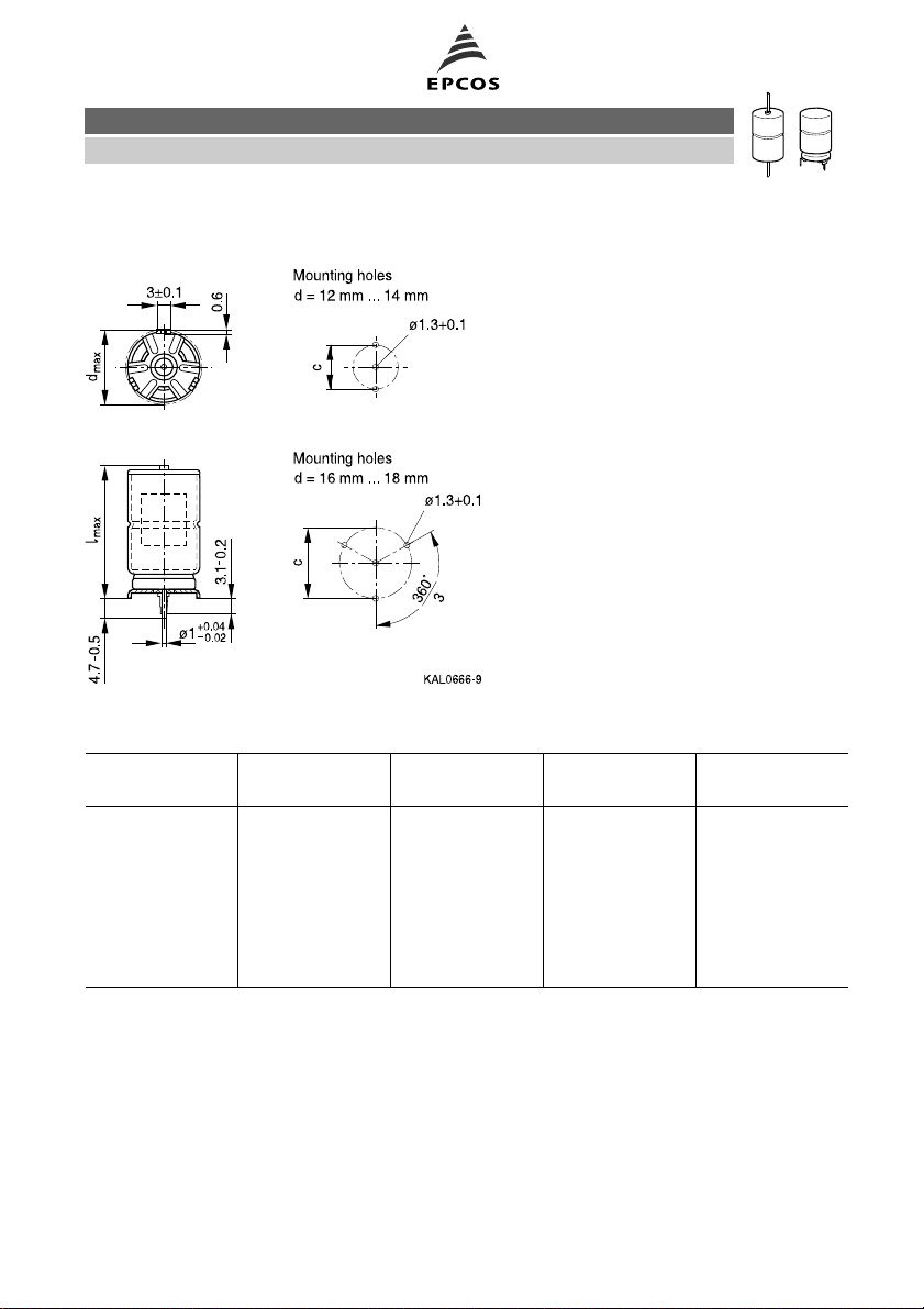
Soldering star capacitors
Dimensional drawing
Dimensions, weights and packing units
B41692, B41792
d × l d
max
× I
max
c ±0.1 Approx. weight Packing units
mm mm mm g pcs.
12 × 30 13.5 × 32 12.5 5.4 480
14 × 25 15.5 × 27 14.5 6.1 480
14 × 30 15.5 × 32 14.5 7.2 480
16 × 30 17.5 × 32 16.5 9.4 300
16 × 39 17.5 × 41.5 16.5 12.2 200
18 × 30 19.5 × 32 18.5 11.8 300
18 × 39 19.5 × 41.5 18.5 15.4 200
Important notes at the end of this document.
Page 5 of 16Please read Cautions and warnings and

B41692, B41792
Long useful life, compact up to 140 °C
Overview of available types
VR(V DC) 25 40 63
Case dimensions d × l (mm)
CR(µF)
220 12 × 30
330 14 × 30
470 12 × 30 16 × 30
680 12 × 30 14 × 30 16 × 39
18 × 30
1000 14 × 25 16 × 30 18 × 39
1100 20 × 29
1500 14 × 30 16 × 39
18 × 30
1800 21 × 39
2200 16 × 39
18 × 30
3300 18 × 39
18 × 39
20 × 29
21 × 39
21 × 49
20 × 29
4400 21 × 49
5000 21 × 39
6800 21 × 49
Important notes at the end of this document.
Page 6 of 16Please read Cautions and warnings and

B41692, B41792
Long useful life, compact up to 140 °C
Case dimensions and ordering codes
V
R
V DC
C
R
100 Hz
20 °C
µF
Case
dimensions
d × l
mm
Ordering code
Axial pallet
Ordering code
Axial reel
Ordering code
Soldering star
25 680 12 × 30 B41692A5687Q007 B41692A5687Q009 B41792A5687Q000
1000 14 × 25 B41692A5108Q007 B41692A5108Q009 B41792A5108Q000
1500 14 × 30 B41692A5158Q007 B41692A5158Q009 B41792A5158Q000
2200 16 × 39 B41692A5228Q007 B41792A5228Q000
2200 ∇ 18 × 30 B41692B5228Q007 B41792B5228Q000
3300 18 × 39 B41692A5338Q007 B41792A5338Q000
3300 ∇ 20 × 29 B41692B5338Q007
5000 21 × 39 B41692A5508Q007
6800 21 × 49 B41692A5688Q007
40 470 12 × 30 B41692A7477Q007 B41692A7477Q009 B41792A7477Q000
680 14 × 30 B41692A7687Q007 B41692A7687Q009 B41792A7687Q000
1000 16 × 30 B41692A7108Q007 B41692A7108Q009 B41792A7108Q000
1500 16 × 39 B41692A7158Q007 B41792A7158Q000
1500 ∇ 18 × 30 B41692B7158Q007 B41792B7158Q000
2200 18 × 39 B41692A7228Q007 B41792A7228Q000
2200 ∇ 20 × 29 B41692B7228Q007
3300 21 × 39 B41692A7338Q007
4400 21 × 49 B41692A7448Q007
63 220 12 × 30 B41692A8227Q007 B41692A8227Q009 B41792A8227Q000
330 14 × 30 B41692A8337Q007 B41692A8337Q009 B41792A8337Q000
470 16 × 30 B41692A8477Q007 B41692A8477Q009 B41792A8477Q000
680 16 × 39 B41692A8687Q007 B41792A8687Q000
680 ∇ 18 × 30 B41692B8687Q007 B41792B8687Q000
1000 18 × 39 B41692A8108Q007 B41792A8108Q000
1100 20 × 29 B41692A8118Q007
1800 21 × 39 B41692A8188Q007
2200 21 × 49 B41692A8228Q007
∇ Variant with different case dimensions
Important notes at the end of this document.
Page 7 of 16Please read Cautions and warnings and

B41692, B41792
Long useful life, compact up to 140 °C
Technical data
C
100 Hz
20 °C
µF
ESR
R
100 Hz
20 °C
mΩ
typ
ESR
max
100 Hz
20 °C
mΩ
ESR
max
100 Hz
40 °C
mΩ
ESR
max
10 kHz
20 °C
mΩ
Z
max
100 kHz
20 °C
mΩ
I
AC,max
10 kHz
85 °C
A
I
AC,max
10 kHz
105 °C
A
I
AC,max
10 kHz
125 °C
A
I
AC,R
10 kHz
125 °C
A
I
AC,max
10 kHz
140 °C
A
VR= 25 V DC
680 150 250 1600 165 155 4.5 3.8 2.85 1.95 1.25
1000 100 170 1200 120 112 4.8 4.1 3.1 2.1 1.4
1500 70 120 800 82 77 6.2 5.3 4.0 2.75 1.8
2200 50 82 550 55 50 9.2 7.9 5.9 4.05 2.6
2200 ∇ 48 79 550 52 48 9.1 7.8 5.8 4.0 2.6
3300 32 53 360 35 33 12.7 10.8 8.1 5.5 3.6
3300 ∇ 33 55 360 38 36 10.6 9.1 6.8 4.6 3.0
5000 22 37 240 27 27 15.0 12.9 9.6 6.6 4.3
6800 17 28 180 20 20 19.0 16.3 12.1 8.3 5.4
VR= 40 V DC
470 145 240 1400 135 128 4.9 4.2 3.1 2.15 1.4
680 105 170 1000 95 90 6.0 5.1 3.8 2.6 1.7
1000 73 120 660 70 67 6.9 5.9 4.4 3.0 2.0
1500 49 80 450 50 48 9.6 8.2 6.1 4.2 2.7
1500 ∇ 46 77 450 45 43 9.7 8.3 6.1 4.2 2.7
2200 32 53 300 30 29 13.3 11.4 8.5 5.8 3.8
2200 ∇ 34 55 300 33 32 10.9 9.3 6.9 4.8 3.1
3300 23 39 200 23 23 15.4 13.1 9.8 6.7 4.4
4400 18 30 160 18 18 19.4 16.6 12.3 8.5 5.5
VR= 63 V DC
220 210 350 1600 145 138 4.7 4.0 3.0 2.05 1.35
330 140 240 1100 100 95 5.9 5.0 3.7 2.55 1.7
470 105 170 750 75 72 6.8 5.8 4.3 3.0 2.0
680 71 120 500 55 53 9.4 8.0 6.0 4.1 2.7
680 ∇ 69 114 500 50 48 9.4 8.0 6.0 4.1 2.7
1000 50 78 350 35 34 13.0 11.1 8.2 5.7 3.7
1100 48 75 330 36 35 10.9 9.3 6.9 4.8 3.1
1800 30 47 220 23 23 15.5 13.2 9.8 6.7 4.4
2200 25 38 175 19 19 19.3 16.5 12.3 8.5 5.5
∇ Variant with different case dimensions
Important notes at the end of this document.
Page 8 of 16Please read Cautions and warnings and

B41692, B41792
Long useful life, compact up to 140 °C
Useful life
depending on ambient temperature TAunder ripple current operating conditions at V
Useful life
depending on case temperature TCunder ripple current operating conditions at V
R
1)
R
1)
1) Refer to chapter "General technical information, 5.3 Calculation of useful life" for an explanation on how to interpret the useful life
graphs.
Important notes at the end of this document.
Page 9 of 16Please read Cautions and warnings and

B41692, B41792
Long useful life, compact up to 140 °C
Useful life
depending on ambient temperature TAunder ripple current operating conditions at V
VR= 25 V: Vop≤ 20 V;
VR= 40 V: Vop≤ 35 V;
VR= 63 V: Vop≤ 55 V
Useful life
depending on case temperature TCunder ripple current operating conditions at V
op
VR= 25 V: Vop≤ 20 V;
VR= 40 V: Vop≤ 35 V;
VR= 63 V: Vop≤ 55 V
2)
op
2)
2) Refer to chapter "General technical information, 5.3 Calculation of useful life" for an explanation on how to interpret the useful life
graphs.
Important notes at the end of this document.
Page 10 of 16Please read Cautions and warnings and

B41692, B41792
Long useful life, compact up to 140 °C
Important notes at the end of this document.
Page 11 of 16Please read Cautions and warnings and

B41692, B41792
Long useful life, compact up to 140 °C
Frequency factor of permissible ripple
current IACversus frequency f
Equivalent series resistance ESR
versus frequency f
Typical behavior for 2200 µF/25 V
Frequency characteristics of ESR
Typical behavior
Impedance Z
versus frequency f
Typical behavior for 2200 µF/25 V
Important notes at the end of this document.
Page 12 of 16Please read Cautions and warnings and

B41692, B41792
Long useful life, compact up to 140 °C
Cautions and warnings
Personal safety
The electrolytes used by EPCOS have not only been optimized with a view to the intended
application, but also with regard to health and environmental compatibility. They do not contain
any solvents that are detrimental to health, e.g. dimethyl formamide (DMF) or dimethyl acetamide
(DMAC).
Furthermore, part of the high-voltage electrolytes used by EPCOS are self-extinguishing. They
contain flame-retarding substances which will quickly extinguish any flame that may have been
ignited.
As far as possible, EPCOS does not use any dangerous chemicals or compounds to produce
operating electrolytes. However, in exceptional cases, such materials must be used in order to
achieve specific physical and electrical properties because no safe substitute materials are
currently known. However, the amount of dangerous materials used in our products has been
limited to an absolute minimum. Nevertheless, the following rules should be observed when
handling Al electrolytic capacitors:
Any escaping electrolyte should not come into contact with eyes or skin.
If electrolyte does come into contact with the skin, wash the affected parts immediately with
running water. If the eyes are affected, rinse them for 10 minutes with plenty of water. If
symptoms persist, seek medical treatment.
Avoid breathing in electrolyte vapor or mists. Workplaces and other affected areas should be
well ventilated. Clothing that has been contaminated by electrolyte must be changed and
rinsed in water.
Important notes at the end of this document.
Page 13 of 16Please read Cautions and warnings and

B41692, B41792
Long useful life, compact up to 140 °C
Product safety
The table below summarize the safety instructions that must be observed without fail. A detailed
description can be found in the relevant sections of chapter "General technical information".
Topic Safety information Reference
Chapter "General
technical information"
Polarity Make sure that polar capacitors are connected
with the right polarity.
1
"Basic construction of
aluminum electrolytic
capacitors"
Reverse voltage Voltages polarity classes should be prevented by
connecting a diode.
Upper category
Do not exceed the upper category temperatur. 7.2
temperature
3.1.6
"Reverse voltage"
"Maximum permissible
operating temperature"
Maintenance Make periodic inspections of the capacitors.
Before the inspection, make sure that the power
10
"Maintenance"
supply is turned off and carefully discharge the
electricity of the capacitors.
Do not apply any mechanical stress to the
capacitor terminals.
Mounting
position of screw
terminal capacitors
Do not mount the capacitor with the terminals
(safety vent) upside down.
11.1.
"Mounting positions of
capacitors with screw
terminals"
Mounting of
single-ended
capacitors
The internal structure of single-ended capacitors
might be damaged if excessive force is applied to
the lead wires.
Avoid any compressive, tensile or flexural stress.
11.4
"Mounting
considerations for
single-ended capacitors"
Do not move the capacitor after soldering to PC
board.
Do not pick up the PC board by the soldered
capacitor.
Do not insert the capacitor on the PC board with a
hole space different to the lead space specified.
Robustness of
terminals
The following maximum tightening torques must
not be exceeded when connecting screw
11.3
"Mounting torques"
terminals:
M5: 2 Nm
M6: 2.5 Nm
Soldering Do not exceed the specified time or temperature
limits during soldering.
11.5
"Soldering"
Important notes at the end of this document.
Page 14 of 16Please read Cautions and warnings and

B41692, B41792
Long useful life, compact up to 140 °C
Topic Safety information Reference
Chapter "General
technical information"
Soldering,
cleaning agents
Passive
flammability
Active
flammability
Do not allow halogenated hydrocarbons to come
into contact with aluminum electrolytic capacitors.
11.6
"Cleaning agents"
Avoid external energy, such as fire or electricity. 8.1
"Passive flammability"
Avoid overload of the capacitors. 8.2
"Active flammability"
Reference
Chapter "Capacitors
with screw terminals"
Breakdown strength
of insulating
Do not damage the insulating sleeve, especially
when ring clips are used for mounting.
"Screw terminals -
accessories"
sleeves
Important notes at the end of this document.
Page 15 of 16Please read Cautions and warnings and

Important notes
The following applies to all products named in this publication:
1. Some parts of this publication contain statements about the suitability of our products for
certain areas of application. These statements are based on our knowledge of typical re-
quirements that are often placed on our products in the areas of application concerned. We
nevertheless expressly point out that such statements cannot be regarded as binding
statements about the suitability of our products for a particular customer application.
As a rule, EPCOS is either unfamiliar with individual customer applications or less familiar
with them than the customers themselves. For these reasons, it is always ultimately incumbent on the customer to check and decide whether an EPCOS product with the properties described in the product specification is suitable for use in a particular customer application.
2. We also point out that in individual cases, a malfunction of passive electronic compon-
ents or failure before the end of their usual service life cannot be completely ruled out
in the current state of the art, even if they are operated as specified. In customer applica-
tions requiring a very high level of operational safety and especially in customer applications
in which the malfunction or failure of a passive electronic component could endanger human
life or health (e.g. in accident prevention or life-saving systems), it must therefore be ensured
by means of suitable design of the customer application or other action taken by the customer
(e.g. installation of protective circuitry or redundancy) that no injury or damage is sustained by
third parties in the event of malfunction or failure of a passive electronic component.
3. The warnings, cautions and product-specific notes must be observed.
4. In order to satisfy certain technical requirements, some of the products described in this
publication may contain substances subject to restrictions in certain jurisdictions (e.g.
because they are classed as “hazardous”). Useful information on this will be found in our
Material Data Sheets on the Internet (www.epcos.com/material). Should you have any more
detailed questions, please contact our sales offices.
5. We constantly strive to improve our products. Consequently, the products described in this
publication may change from time to time. The same is true of the corresponding product
specifications. Please check therefore to what extent product descriptions and specifications
contained in this publication are still applicable before or when you place an order. We also
reserve the right to discontinue production and delivery of products. Consequently, we
cannot guarantee that all products named in this publication will always be available.
6. Unless otherwise agreed in individual contracts, all orders are subject to the current ver-
sion of the “General Terms of Delivery for Products and Services in the Electrical Industry” published by the German Electrical and Electronics Industry Association
(ZVEI).
7. The trade names EPCOS, EPCOS-JONES, BAOKE, Alu-X, CeraDiode, CSSP, MLSC,
PhaseCap, PhaseMod, SIFERRIT, SIFI, SIKOREL, SilverCap, SIMID, SIOV, SIP5D, SIP5K,
UltraCap, WindCap are trademarks registered or pending in Europe and in other countries.
Further information will be found on the Internet at www.epcos.com/trademarks.
Page 16 of 16
 Loading...