

Capacitors for Power Electronics
Series/Type: B253*
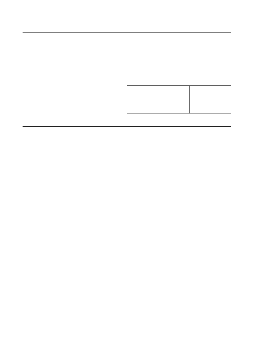
The following products presented in this data sheet are being withdrawn.
Ordering Code Substitute Product Date of
Withdrawal
B25355L8367K004 B25650 2001-04-06 2001-07-31 2001-12-31
B25355L7477K004 B25650 2001-04-06 2001-07-31 2001-12-31
B25355L6627K004 B25650 2001-04-06 2001-07-31 2001-12-31
B25355L4887K004 B25650 2001-04-06 2001-07-31 2001-12-31
B25355L2856K004 B25650 2001-04-06 2001-07-31 2001-12-31
B25355L2805K001 B25650 2001-04-06 2001-07-31 2001-12-31
B25355L2635K001 B25650 2001-04-06 2001-07-31 2001-12-31
B25355L2586K004 B25650 2001-04-06 2001-07-31 2001-12-31
B25355L2566K004 B25650 2001-04-06 2001-07-31 2001-12-31
B25355L2466K004 B25650 2001-04-06 2001-07-31 2001-12-31
B25355L2406K001 B25650 2001-04-06 2001-07-31 2001-12-31
B25355L2326K004 B25650 2001-04-06 2001-07-31 2001-12-31
B25355L2316K001 B25650 2001-04-06 2001-07-31 2001-12-31
B25355L2206K001 B25650 2001-04-06 2001-07-31 2001-12-31
Deadline Last
Orders
Last Shipments
Ordering Code Substitute Product Date of
Withdrawal
B25355L2166K001 B25650 2001-04-06 2001-07-31 2001-12-31
B25355L2107K004 B25650 2001-04-06 2001-07-31 2001-12-31
B25355L2106K001 B25650 2001-04-06 2001-07-31 2001-12-31
B25355L1806K004 B25650 2001-04-06 2001-07-31 2001-12-31
B25355L1406K001 B25650 2001-04-06 2001-07-31 2001-12-31
B25355L1316K001 B25650 2001-04-06 2001-07-31 2001-12-31
B25355L1277K004 B25650 2001-04-06 2001-07-31 2001-12-31
B25355L1227K004 B25650 2001-04-06 2001-07-31 2001-12-31
B25355L1206K001 B25650 2001-04-06 2001-07-31 2001-12-31
B25355L1166K001 B25650 2001-04-06 2001-07-31 2001-12-31
B25355L1147K904 B25650 2001-04-06 2001-07-31 2001-12-31
B25355L1147K004 B25650 2001-04-06 2001-07-31 2001-12-31
B25355L1117K004 B25650 2001-04-06 2001-07-31 2001-12-31
B25355L0307K004 B25650 2001-04-06 2001-07-31 2001-12-31
B25355L0167K004 B25650 2001-04-06 2001-07-31 2001-12-31
B25355J3805K001 B25650 2001-04-06 2001-07-31 2001-12-31
B25355J3635K001 B25650 2001-04-06 2001-07-31 2001-12-31
B25355J3504K001 B25650 2001-04-06 2001-07-31 2001-12-31
B25355J3405K001 B25650 2001-04-06 2001-07-31 2001-12-31
B25355J3254K001 B25650 2001-04-06 2001-07-31 2001-12-31
B25355J3205K001 B25650 2001-04-06 2001-07-31 2001-12-31
B25355J3166K001 B25650 2001-04-06 2001-07-31 2001-12-31
B25355J3106K001 B25650 2001-04-06 2001-07-31 2001-12-31
B25355J3105K001 B25650 2001-04-06 2001-07-31 2001-12-31
B25355J2504K001 B25650 2001-04-06 2001-07-31 2001-12-31
B25355J2405K001 B25650 2001-04-06 2001-07-31 2001-12-31
B25355J2205K001 B25650 2001-04-06 2001-07-31 2001-12-31
B25355J2105K001 B25650 2001-04-06 2001-07-31 2001-12-31
B25355J1805K001 B25650 2001-04-06 2001-07-31 2001-12-31
B25355J1635K001 B25650 2001-04-06 2001-07-31 2001-12-31
B25355J1405K001 B25650 2001-04-06 2001-07-31 2001-12-31
B25355J1205K001 B25650 2001-04-06 2001-07-31 2001-12-31
B25355J1106K001 B25650 2001-04-06 2001-07-31 2001-12-31
B25355J1105K001 B25650 2001-04-06 2001-07-31 2001-12-31
B25355G6405K001 B25650 2001-04-06 2001-07-31 2001-12-31
B25355G6205K001 B25650 2001-04-06 2001-07-31 2001-12-31
B25355G2256K001 B25650 2001-04-06 2001-07-31 2001-12-31
B25355C8297K005 B25650 2001-04-06 2001-07-31 2001-12-31
B25355C8197K005 B25650 2001-04-06 2001-07-31 2001-12-31
B25355C7387K005 B25650 2001-04-06 2001-07-31 2001-12-31
B25355C7247K005 B25650 2001-04-06 2001-07-31 2001-12-31
Deadline Last
Orders
Last Shipments

Ordering Code Substitute Product Date of
Withdrawal
B25355C6527K005 B25650 2001-04-06 2001-07-31 2001-12-31
B25355C6337K005 B25650 2001-04-06 2001-07-31 2001-12-31
B25355C4727K005 B25650 2001-04-06 2001-07-31 2001-12-31
B25355C4477K005 B25650 2001-04-06 2001-07-31 2001-12-31
For further information please contact your nearest EPCOS sales office, which will also support
you in selecting a suitable substitute. The addresses of our worldwide sales network are
presented at www.epcos.com/sales.
Deadline Last
Orders
Last Shipments
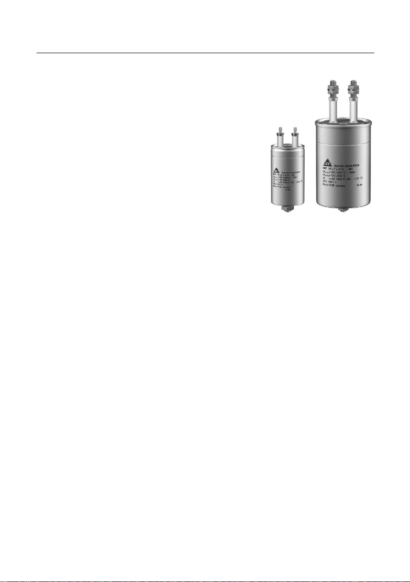
MP DC Capacitors
Smoothing, Supporting, Discharge
High peak-current capability
Wide capacitance and voltage range
Construction
● Self-healing
● Paper dielectric
● Oil and hard-wax-impregnated tubular
windings (no PCB)
● Metal-sprayed end faces ensure
reliable contacting
● Tubular aluminum case
● 1-pole and 2-pole versions
● Ceramic or plastic lead-throughs
● With mounting bolt
(325 mm high capacitors without mounting bolt)
Terminals
● Screw terminals M12
● Screw-clamping terminals
● Tab connectors 6,3 mm
Mounting parts
● If the vibration stress is ≤ 5
in diameter and ≤ 160 mm in height, the bolt is used for mounting.
● For capacitors without mounting bolt and in case of a vibration
stress > 5g as well as for larger-sized capacitors refer to chapter
“Mounting parts”.
g
and the capacitors are ≤ 60 mm
B 25 355
Grounding
● Mounting bolt or grounding strap
for grounding in accordance with VDE 0100
● Grounding identification in accordance with DIN 40 011
Overpressure disconnector (mechanical)
When the overpressure disconnector responds,
the capacitor extends by up to 8 mm.
So leave sufficient space above the terminals when mounting the capacitor.
Individual data sheets
Individual capacitors of this series are specified in detail
(incl. thermal data) on pages 78 … 93.
Upon request, these data sheets are available for each capacitor type.
Siemens Matsushita Components 67
B 25 355
Smoothing, Supporting, Discharge
Technical data
Standards IEC 1071-1/2
EN 61071-1/2
VDE 0560 part 120 and 121
Dielectric dissipation factor tan δ
0
Max. repetitive rate
of voltage rise (du/dt)
max
Max. non-repetitive rate
of voltage rise (du/dt)
s
Climatic data:
Min. operating temperature Θ
Max. operating temperature Θ
min
max
Average relative humidity ≤ 95 % (screw terminals, tab connectors)
Failure quota α
Load duration
Storage temperature limit Θ
FQ(co)
α
FQ(sto)
t
LD(co)
t
LD(sto)
stg
IEC climatic category
(IEC 68-1 and 2)
Test A, cold
Test B, dry heat
Test Ca, damp heat, steady state
Values after test Ca:
Capacitance change ∆C/
Insulation resistance
Self-discharge time constant τ =
C
R
is
R
·
C
is
Dissipation factor change ∆tan δ
–4
50 · 10
î
----
C
I
S
----
C
– 40 °C
+ 70 °C
≤ 75 % (screw-clamping terminals)
300 failures per 109 component hours
3000 failures per 109 component hours
100 000 h
10 000 h
– 55/+ 85 °C (screw terminals, tab connectors)
– 55/+ 70 °C (screw-clamping terminals)
40/070/56
– 40 °C
+ 70 °C
56 days/40 °C/93 % rel. humidity
≤ 1 %
C
N
Screw terminals,
tab connectors
Screw-clamping
terminals
≤ 1 µF ≥ 5000 MΩ –
> 1 µF ≥ 5000 s ≥ 1000 s
≤ 10 · 10
–4
68 Siemens Matsushita Components
Technical data
Test data:
DC test voltage between terminals
U
TT
AC test voltage between terminals
and case
Insulation resistance
Self-discharge time constant τ =
U
TC
R
is
R
is
Dissipation factor tan δ
B 25 355
Smoothing, Supporting, Discharge
1,5 ·
U
, 10 s
N(co)
2 ·
U
+ 1000 V, 50 Hz, 10 s
i
C
≤ 1 µF ≥ 5000 MΩ –
·
C
> 1 µF ≥ 5000 s ≥ 3000 s
≤ 10 µF: ≤ 100 · 10–4,
>10µF: < 70 · 10–4,
N
Screw terminals,
tab connectors
measuring frequency 1 kHz
measuring frequency 120 Hz
Screw-clamping
terminals
Siemens Matsushita Components 69
B 25 355
Smoothing, Supporting, Discharge
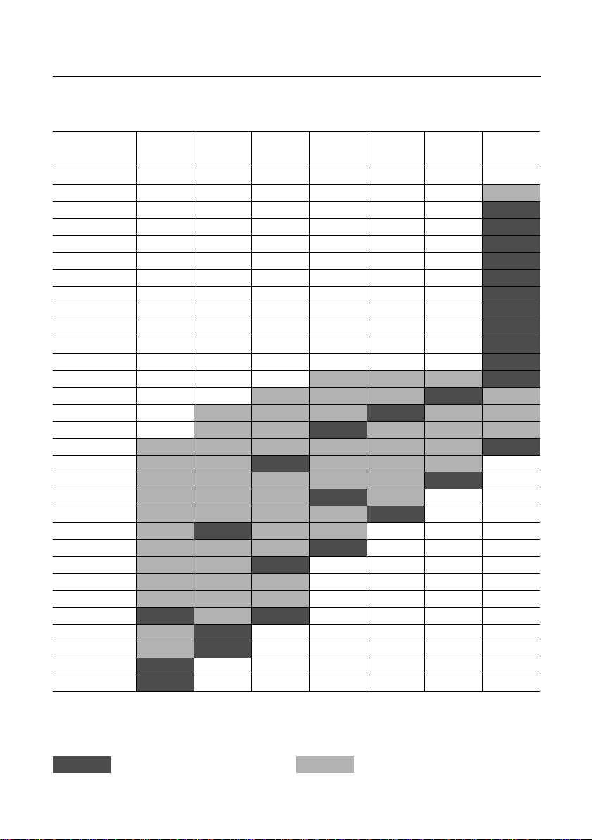
Available ratings
U
U
C
10
16
20
31,5
40
110
140
160
190
220
245
270
290
300
330
360
380
400
430
470
520
620
720
880
N(co)
N(sto)
(µF)
R
0,5
1,0
2,0
4,0
6,3
8,0
(V) DC
(V) DC
450
560
600
750
750
940
850
1100
1200
1500
1400
1800
1600
2000
Data book range Upon request
70 Siemens Matsushita Components
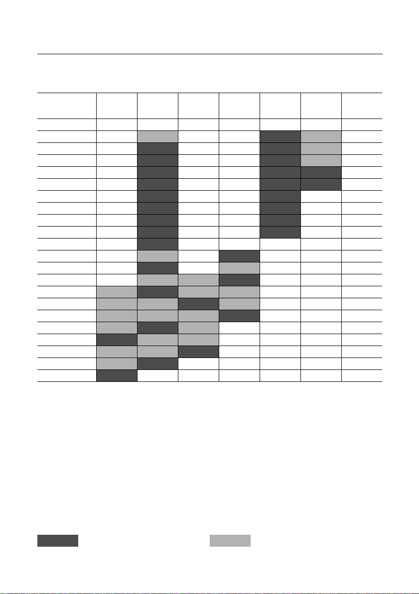
Available ratings
U
(V) DC
N(co)
U
(V) DC
N(sto)
C
(µF)
R
0,25
0,5
1,0
2,0
4,0
6,3
8,0
10
16
20
25
31,5
32
40
46
56
58
80
85
105
145
1800
2300
2000
2500
2400
3000
B 25 355
Smoothing, Supporting, Discharge
2800
3500
3200
4000
6300
7900
Data book range Upon request
Siemens Matsushita Components 71
B 25 355
Smoothing, Supporting, Discharge
Characteristics and ordering codes
1)
C
I
N
max
µF
AîA
U
= DC 450 V
N(co)
470 40 26000 31000 2,8 240 99,3 × 248 3 2300 B25355-C4477-K005
720 40 32000 36000 2,6 240 121,6 × 248 3 3500 B25355-C4727-K005
880 100 40000 48000 1,4 200 121,6 × 325 2a 4500 B25355-L4887-K004
U
= DC 600 V
N(co)
330 40 23000 33000 2,9 240 99,3 × 248 3 2300 B25355-C6337-K005 78
520 40 36000 42000 2,6 240 121,6 × 248 3 3500 B25355-C6527-K005
620 100 43000 50000 1,5 200 121,6 × 325 2a 4500 B25355-L6627-K004
U
= DC 750 V
N(co)
245 40 19000 34000 3,0 240 99,3 × 248 3 2300 B25355-C7247-K005
380 40 30000 42000 2,7 240 121,6 × 248 3 3500 B25355-C7387-K005
470 100 38000 52000 1,6 200 121,6 × 325 2a 4500 B25355-L7477-K004 80
U
= DC 850 V
N(co)
190 40 17000 36000 3,1 240 99,3 × 248 3 2300 B25355-C8197-K005
290 40 26000 44000 2,8 240 121,6 × 248 3 3500 B25355-C8297-K005
360 100 32000 54000 1,7 200 121,6 × 325 2a 4500 B25355-L8367-K004
U
= DC 1200 V
N(co)
160 80 16000 40000 3,0 180 121,6 × 176 1a 2500 B25355-L0167-K004
300 100 40000 75000 1,9 200 121,6 × 325 2a 4500 B25355-L0307-K004 82
U
= DC 1400 V
N(co)
140 80 14000 35000 3,0 180 121,6 × 176 1a 2500 B25355-L1147-K004
270 100 27000 67000 1,9 210 121,6 × 325 2a 4500 B25355-L1277-K004
I
R
L
s
S
20 °C
A
mΩ
U
N(sto)
U
i
U
N(sto)
U
i
U
N(sto)
U
i
U
N(sto)
U
i
U
N(sto)
U
i
U
N(sto)
U
i
Dimensions
self
d×l
nH
mm
= DC 560 V
= AC 400 V
= DC 750 V
= AC 530 V
= DC 940 V
= AC 670 V
= DC 1100 V
= AC 780 V
= DC 1500 V
= AC 1100 V
= DC 1800 V
= AC 1300 V
Fig. Appr.
weight
g
û
= 560 V
u
= 680 V
s
û
= 750 V
u
= 900 V
s
û
= 940 V
u
= 1100 V
s
û
= 1100 V
u
= 1300 V
s
û
= 1500 V
u
= 1800 V
s
û
= 1800 V
u
= 2100 V
s
Ordering code Pg.
U
= DC 680V, 10 s
TT
U
= AC 2000 V, 10 s
TC
U
= DC 900V, 10 s
TT
U
= AC 2100 V, 10 s
TC
U
= DC 1150 V, 10 s
TT
U
= AC 2400 V, 10 s
TC
U
= DC 1300 V, 10 s
TT
U
= AC 2600 V, 10 s
TC
U
= DC 1800 V, 10 s
TT
U
= AC 3200 V, 10 s
TC
U
= DC 2100 V, 10 s
TT
U
= AC 3600 V, 10 s
TC
1) Capacitance tolerance ± 10 %
72 Siemens Matsushita Components

B 25 355
Smoothing, Supporting, Discharge
Characteristics and ordering codes
1)
C
I
N
max
µF
AîA
U
= DC 1600 V
N(co)
1 16 700 1700 17,0 70 35,0 × 57 4 70 B25355-J1105-K001
2 16 400 1000 38,0 110 35,0 × 86 4 100 B25355-J1205-K001
4 16 800 2000 22,0 110 35,0 × 86 4 100 B25355-J1405-K001
6,3 16 1200 3100 16,0 110 40,0 × 86 4 130 B25355-J1635-K001
8 16 1600 4000 14,0 110 45,0 × 86 4 160 B25355-J1805-K001
10 16 2000 5000 12,0 110 50,0 × 86 4 200 B25355-J1106-K001
16 20 3200 8000 5,7 110 79,2 × 10⁴ 5 600 B25355-L1166-K001
20 20 4000 10000 4,7 110 79,2 × 10⁴ 5 600 B25355-L1206-K001
31,5 20 6300 15000 3,7 110 99,3 × 10⁴ 5 950 B25355-L1316-K001
40 20 4000 10000 8,3 180 79,2 × 176 5 1000 B25355-L1406-K001 84
110 80 11000 27000 3,5 180 121,6 × 176 1a 2500 B25355-L1117-K004
220 100 22000 55000 2,0 210 121,6 × 325 2a 4500 B25355-L1227-K004
U
= DC 1800 V
N(co)
80 80 11000 28000 3,9 190 121,6 × 176 1a 2500 B25355-L1806-K004
145 100 20000 51000 2,3 210 121,6 × 325 2a 4500 B25355-L1147-K904
U
= DC 2000 V
N(co)
0,5 16 450 1100 22,0 70 35,0 × 57 4 70 B25355-J2504-K001
1 16 900 2200 14,0 70 40,0 × 57 4 90 B25355-J2105-K001
2 16 600 1500 28,0 110 35,0 × 86 4 100 B25355-J2205-K001
4 16 1200 3000 17,0 110 45,0 × 86 4 160 B25355-J2405-K001
6,3 20 1800 4700 8,7 110 64,2 × 10⁴ 5 400 B25355-L2635-K001
8 20 2400 6000 7,3 110 79,2 × 10⁴ 5 600 B25355-L2805-K001
10 20 3000 7500 6,0 110 79,2 × 10⁴ 5 600 B25355-L2106-K001
16 20 4800 12000 4,3 110 89,3 × 10⁴ 5 800 B25355-L2166-K001
20 20 6000 15000 3,8 110 99,3 × 10⁴ 5 950 B25355-L2206-K001 86
31,5 20 3100 7800 8,0 180 89,3 × 176 5 1300 B25355-L2316-K001
40 20 4000 10000 6,6 180 99,3 × 176 5 1600 B25355-L2406-K001
58 80 10000 25000 4,4 190 121,6 × 176 1b 2500 B25355-L2586-K004
105 100 18000 45000 2,6 230 121,6 × 325 2b 4500 B25355-L2107-K004
I
R
L
s
S
20 °C
A
mΩ
U
N(sto)
U
i
U
N(sto)
U
i
U
N(sto)
U
i
Dimensions
self
d×l
nH
mm
= DC 2000 V
= AC 1450 V
= DC 2300 V
= AC 1700 V
= DC 2500 V
= AC 1800 V
Fig. Appr.
weight
g
û
= 2000 V
u
= 2400 V
s
û
= 2300 V
u
= 2700 V
s
û
= 2500 V
u
= 3000 V
s
Ordering code Pg.
U
= DC 2400 V, 10 s
TT
U
= AC 3900 V, 10 s
TC
U
= DC 2700 V, 10 s
TT
U
= AC 4400 V, 10 s
TC
U
= DC 3000 V, 10 s
TT
U
= AC 4600 V, 10 s
TC
1) Capacitance tolerance ± 10 %
Siemens Matsushita Components 73

B 25 355
Smoothing, Supporting, Discharge
Characteristics and ordering codes
1)
C
I
N
max
µF
AîA
U
= DC 2400 V
N(co)
46
80 9000 22000 4,7 200 121,6 × 176 1b 2500 B25355-L2466-K004
85 100 16000 40000 2,7 230 121,6 × 325 2b 4500 B25355-L2856-K004
U
= DC 2800 V
N(co)
2)
25
20 5000 12000 8,0 180 99,3 × 176 6 1600 B25355-G2256-K001
32 60 7000 18000 5,4 220 121,6 × 176 1b 2500 B25355-L2326-K004 88
56 100 12000 31000 3,2 250 121,6 × 325 2b 4500 B25355-L2566-K004
U
= DC 3200 V
N(co)
0,25 16 250 600 27,0 70 35,0 × 57 4 70 B25355-J3254-K001
0,5 16 500 1200 16,0 70 40,0 × 57 4 90 B25355-J3504-K001 90
1 16 500 1200 35,0 110 40,0 × 86 4 130 B25355-J3105-K001
2 16 1000 2400 20,0 110 50,0 × 86 4 200 B25355-J3205-K001
4 20 2000 4800 8,7 110 79,2 × 10⁴ 5 600 B25355-L3405-K001
6,3 20 3100 7500 6,0 110 89,3 × 10⁴ 5 800 B25355-L3635-K001
8 20 4000 9600 5,1 110 99,3 × 10⁴ 5 950 B25355-L3805-K001
10 20 5000 12000 7,8 180 79,2 × 176 5 1000 B25355-L3106-K001
16 20 8000 19000 5,6 180 99,3 × 176 5 1600 B25355-L3166-K001
U
= DC 6300 V
N(co)
2)
2
20 2000 5000 18,0 180 79,2 × 176 6 1000 B25355-G6205-K001
2)
4
20 4000 10000 10,0 180 99,3 × 176 6 1600 B25355-G6405-K001 92
I
R
L
s
S
20 °C
A
mΩ
U
N(sto)
U
i
U
N(sto)
U
i
U
N(sto)
U
i
U
N(sto)
Dimensions
self
d×l
nH
mm
= DC 3000 V
= AC 2200 V
= DC 3500 V
= AC 2500 V
= DC 4000 V
= AC 2900 V
= DC 7900 V
Fig. Appr.
weight
g
û
= 3000 V
u
= 3600 V
s
û
= 3500 V
u
= 4200 V
s
û
= 4000 V
u
= 4800 V
s
û
= 7900 V
u
= 9500 V
s
Ordering code Pg.
U
= DC 3600 V, 10 s
TT
U
= AC 5400 V, 10 s
TC
U
= DC 4200 V, 10 s
TT
U
= AC 6000 V, 10 s
TC
U
= DC 4800 V, 10 s
TT
U
= AC 6800 V, 10 s
TC
U
= DC 9500 V, 10 s
TT
1) Capacitance tolerance ± 10 %
2) 1-pole capacitor.
No insulated voltage and test voltage between terminal/case needed.
74 Siemens Matsushita Components

B 25 355
Smoothing, Supporting, Discharge
Dimensional drawing 1a/1b
Screw terminals M12
Type with mounting bolt
M12
_
37 4
1
l
2
l
5
~
~
_
176 4
1,5121,6
_
135 min.
16+1
50
_
0,6ø116,2
M12
26 min.
Hex nut
M12 ISO 4035
Washer
13 DIN 433
KLK1420-N
Dimensional drawing 2a/2b
Screw terminals M12
Type without mounting bolt
M12
_
41 6
1
l
2
l
5
ø8,4
~
~
_
325 4
265 min.
_
0,6ø116,2
1,5121,6
1,5
_
26 min.
50
Hex nut
M12 ISO 4035
Washer
13 DIN 433
2
_
+1
11,5
38,5±2
KLK1421-W
Dimensions in mm
Fig. 1a 1b
I
1
I
2
72 –6 90 –6
18 min. 36 min.
Creepage distance 18 mm 36 mm
Clearance 18 mm 26 mm
Max. torque terminals*) 10 Nm 10 Nm
Dimensions in mm
Fig. 2a 2b
I
1
I
2
76 –8 94 –8
18 min. 36 min.
Creepage distance 18 mm 36 mm
Clearance 18 mm 26 mm
Max. torque terminals*) 10 Nm 10 Nm
*) Theterminaltorquemustnotactupontheceramic.Sothe lead should be locked between two nuts.
Mounting parts (included in delivery)
Threaded bolt Max. torque Toothed washer Hex nut
M12 10 Nm J 12,5 DIN 6797 M12 ISO 4035
Siemens Matsushita Components 75

B 25 355
Smoothing, Supporting, Discharge
Dimensional drawing 3
Screw-clamping terminals
15 min.
18 max.
l
ød
1
16+1
d
16,5±0,5
M12
120˚
Dimensions in mm
Connecting washer
B5 DIN 46288
KLK0748-C
Dimensional drawing 4
Tab connectors 6,3 mm
L
e
Tab connector
A 6,3 x 0,8
DIN 46 244
KLK1422-5
28 max.
ld
1
l
Dimensions in mm
dI
–4 ∅
d
1
Creepage
Clearance
distance
99,3 –1,2 248 95,2–0,4 12,7 9,6
121,6 –1,5 248 116,2–0,6 12,7 9,6
+0,5
dII
–0,2+1–2
35 57 8 17 10 5,7
35 86 8 17 10 5,7
*)
+1
e
± 1
1
Creepage
distance
Clearance
L
40 57 8 21 10 9
40 86 8 21 10 9
45 86 8 21 10 9
50 86 12 21 10 9
*) 8 mm = threaded bolt M8
12 mm = threaded bolt M12
Mounting parts (included in delivery)
Threaded bolt Max. torque Toothed washer Hex nut
M8 4 Nm J 8,2 DIN 6797 M8 ISO 4035
M12 10 Nm J 12,5 DIN 6797 M12 ISO 4035 (plastic
nut upon request)
76 Siemens Matsushita Components

B 25 355
Smoothing, Supporting, Discharge
Dimensional drawing 5
Tab connectors 6,3 mm
44,5 max.
20 min.
l
ød
1
16+1
d
35±2
M12
15 min.
Tab connector
A 6,3 x 0,8
DIN 46 244
KLK1423-D
Dimensional drawing 6
Tab connectors 6,3 mm
52,5 max.
28 min.
l
ød
1
16+1
d
19±2
Tab connector
A 6,3 x 0,8
DIN 46 244
M12
KLK1424-L
Dimensions in mm
d
–1,2I –4 ∅
64,2 104 60,2
79,2 104 75,2
d
–0,4
1
Creepage
Clearance
distance
Dimensions in mm
d
–1,2I –4 ∅
d
–0,4
1
Creepage
Clearance
distance
79,2 176 75,2 28 26
99,3 176 95,2 28 26
79,2 176 75,2
89,3 104 85,2 20 15
89,3 176 85,2
99,3 104 95,2
99,3 176 95,2
Mounting parts (included in delivery)
Threaded bolt Max. torque Toothed washer Hex nut
M12 10 Nm J 12,5 DIN 6797 M12 ISO 4035
Siemens Matsushita Components 77

B 25 355
Smoothing, Supporting, Discharge
330 µF / 600 Vdc
Ordering code: B25355-C6337-K005
Characteristics
C
, tol. 330 µF ± 10 %
N
U
N(co)
U
N(sto)
U
i
W
N
I
max
L
self
tan δ
0
R
S
Maximum ratings
û
u
s
î
I
s
(du/dt)
(du/dt)
Test data
U
TT
U
TC
R
·
C
is
tan δ (120 Hz) ≤ 62 · 10
max
s
DC 600 V
DC 750 V
AC 530 V
60 Ws
40 A
240 nH
–4
50 · 10
2,9 mΩ
750 V
900 V
23 kA
33 kA
70 V/µs
100 V/µs
DC 900 V, 10 s
AC 2100 V, 10 s
≥ 3000 s
–4
15 min.
18 max.
4248
_
16+1
1,299,3
_
16,5±0,5
120˚
_
0,4ø95,2
M12
Connecting washer
B5 DIN 46288
KLK1445-9
Climatic data
Θ
min
Θ
max
– 40 °C
+ 70 °C
Humidity Average relative humidity ≤ 75 %
α
FQ(co)
α
FQ(sto)
t
LD(co)
t
LD(sto)
Θ
stg
300/109h
3000/109h
100000 h
10000 h
– 55 to + 70 °C
IEC climatic category: 40/070/56
(IEC 68-1 and 2)
Θ
test
+ 40 °C
Rel. humidity 93 %
t
test
∆C/
C
∆ tan δ≤ 10 · 10
R
·
C
is
56 days
≤ 1%
≥ 1000 s
–4
Design data
Dimensions ∅×
l
99,3 mm × 248 mm
Approx. weight 2300 g
Impregnation Oil
Fixing Threaded bolt M12
Mounting hole 14 mm
Max. torque 10 Nm
Terminals Screw clamps
Terminal
cross section 6,0 mm
2
Creepage distance 12,7 mm
Clearance 9,6 mm
Overpressure disconnector
78 Siemens Matsushita Components

Thermal data
B25355-C6337-K005
B 25 355
Smoothing, Supporting, Discharge
Dielectric power dissipation
versus repetition frequency
û
= 60 V
ac
û
= 54 V
ac
Ohmic power dissipation
versus rms current value
R
(70 °C) = 3,6 mΩ
S
P
D
f
0
P
R
I
Permissible ambient temperature Θ
versus total power dissipation
P
(Upright mounting position)
A
Natural cooling
Forced cooling 2 m/s
Permissible capacitor
temperature
Siemens Matsushita Components 79

B 25 355
Smoothing, Supporting, Discharge
470 µF / 750 Vdc
Ordering code: B25355-L7477-K004
Characteristics
C
, tol. 470 µF ± 10 %
N
U
N(co)
U
N(sto)
U
i
W
N
I
max
L
self
tan δ
R
S
0
DC 750 V
DC 940 V
AC 670 V
130 Ws
100 A
200 nH
–4
50 · 10
1,6 mΩ
Maximum ratings
û
u
s
î
I
s
(du/dt)
(du/dt)
max
s
940 V
1100 V
38 kA
52 kA
80 V/µs
110 V/µs
Test data
U
TT
U
TC
R
·
C
is
tan δ (120 Hz) ≤ 60 · 10
DC 1150 V, 10 s
AC 2400 V, 10 s
≥ 5000 s
–4
Climatic data
Θ
min
Θ
max
– 40 °C
+ 70 °C
Humidity Average relative humidity ≤ 95 %
α
FQ(co)
α
FQ(sto)
t
LD(co)
t
LD(sto)
Θ
stg
300/109h
3000/109h
100000 h
10000 h
– 55 to + 85 °C
IEC climatic category: 40/070/56
(IEC 68-1 and 2)
Θ
test
+ 40 °C
Rel. humidity 93 %
t
test
∆C/
C
∆ tan δ≤ 10 · 10
R
·
C
is
56 days
≤ 1%
≥ 5000 s
–4
M12
Hex nut
M12 ISO 4035
Washer
13 DIN 433
2
_
+1
11,5
_
76 8
5
~
~
18 min.
_
41 6
ø8,4
_
325 4
265 min.
_
0,6ø116,2
1,5121,6
1,5
_
38,5±2
26 min.
50
KLK1446-H
Design data
Dimensions ∅×
l
121,6 mm × 325 mm
Approx. weight 4500 g
Impregnation Oil
Terminals Screw terminals M12
Max. torque 10 Nm
Terminal
cross section 16mm
2
Creepage distance 18 mm
Clearance 18mm
Overpressure disconnector
80 Siemens Matsushita Components

Thermal data
B25355-L7477-K004
B 25 355
Smoothing, Supporting, Discharge
Dielectric power dissipation
versus repetition frequency
û
= 75 V
ac
û
= 68 V
ac
Ohmic power dissipation
versus rms current value
R
(70 °C) = 1,9 mΩ
S
P
D
f
0
P
R
I
Permissible ambient temperature Θ
versus total power dissipation
P
(Upright mounting position)
A
Natural cooling
Forced cooling 2 m/s
Permissible capacitor
temperature
Siemens Matsushita Components 81

B 25 355
Smoothing, Supporting, Discharge
300 µF / 1200 Vdc
Ordering code: B25355-L0307-K004
Characteristics
C
, tol. 300 µF ± 10 %
N
U
N(co)
U
N(sto)
U
i
W
N
I
max
L
self
tan δ
R
S
0
DC 1200 V
DC 1500 V
AC 1100 V
215 Ws
100 A
200 nH
–4
50 · 10
1,9 mΩ
Maximum ratings
û
u
s
î
I
s
(du/dt)
(du/dt)
max
s
1500 V
1800 V
40 kA
75 kA
100 V/µs
250 V/µs
Test data
U
TT
U
TC
R
·
C
is
tan δ (120 Hz) ≤ 59 · 10
DC 1800 V, 10 s
AC 3200 V, 10 s
≥ 5000 s
–4
Climatic data
Θ
min
Θ
max
– 40 °C
+ 70 °C
Humidity Average relative humidity ≤ 95 %
α
FQ(co)
α
FQ(sto)
t
LD(co)
t
LD(sto)
Θ
stg
300/109h
3000/109h
100000 h
10000 h
– 55 to + 85 °C
IEC climatic category: 40/070/56
(IEC 68-1 and 2)
Θ
test
+ 40 °C
Rel. humidity 93 %
t
test
∆C/
C
∆ tan δ≤ 10 · 10
R
·
C
is
56 days
≤ 1%
≥ 5000 s
–4
M12
Hex nut
M12 ISO 4035
Washer
13 DIN 433
2
_
+1
11,5
_
76 8
5
~
~
18 min.
_
41 6
ø8,4
_
325 4
265 min.
_
0,6ø116,2
1,5121,6
1,5
_
38,5±2
26 min.
50
KLK1446-H
Design data
Dimensions ∅×
l
121,6 mm × 325 mm
Approx. weight 4500 g
Impregnation Oil
Terminals Screw terminals M12
Max. torque 10 Nm
Terminal
cross section 16mm
2
Creepage distance 18 mm
Clearance 18mm
Overpressure disconnector
82 Siemens Matsushita Components

Thermal data
B25355-L0307-K004
B 25 355
Smoothing, Supporting, Discharge
Dielectric power dissipation
versus repetition frequency
û
= 120 V
ac
û
= 108 V
ac
Ohmic power dissipation
versus rms current value
R
(70 °C) = 2,3 mΩ
S
P
D
f
0
P
R
I
Permissible ambient temperature Θ
versus total power dissipation
P
(Upright mounting position)
A
Natural cooling
Forced cooling 2 m/s
Permissible capacitor
temperature
Siemens Matsushita Components 83

B 25 355
Smoothing, Supporting, Discharge
40 µF / 1600 Vdc
Ordering code: B25355-L1406-K001
Characteristics
C
, tol. 40 µF ± 10 %
N
U
N(co)
U
N(sto)
U
i
I
max
L
self
tan δ
0
R
S
Maximum ratings
û
u
s
î
I
s
(du/dt)
(du/dt)
Test data
U
TT
U
TC
R
·
C
is
tan δ (120 Hz) ≤ 57 · 10
max
s
DC 1600 V
DC 2000 V
AC 1450 V
20 A
180 nH
–4
50 · 10
8,3 mΩ
2000 V
2400 V
4kA
10 kA
100 V/µs
250 V/µs
DC 2400 V, 10 s
AC 3900 V, 10 s
≥ 5000 s
–4
44,5 max.
20 min.
4176
_
16+1
_
79,2 1,4
_
ø75,2 0,4
35±2
M12
15 min.
Tab connector
A 6,3 x 0,8
DIN 46 244
KLK1448-Y
Climatic data
Θ
min
Θ
max
– 40 °C
+ 70 °C
Humidity Average relative humidity ≤ 95 %
α
FQ(co)
α
FQ(sto)
t
LD(co)
t
LD(sto)
Θ
stg
300/109h
3000/109h
100000 h
10000 h
– 55 to + 85 °C
IEC climatic category: 40/070/56
(IEC 68-1 and 2)
Θ
test
+ 40 °C
Rel. humidity 93 %
t
test
∆C/
C
∆ tan δ≤ 10 · 10
R
·
C
is
56 days
≤ 1%
≥ 5000 s
–4
Design data
Dimensions ∅×
l
79,2 mm × 176 mm
Approx. weight 1000 g
Impregnation Oil
Fixing Threaded bolt M12
Mounting hole 14 mm
Max. torque 10 Nm
Terminals Tab connector 6,3 mm
Terminal
cross section 4 mm
2
Creepage distance 20 mm
Clearance 15mm
Overpressure disconnector
84 Siemens Matsushita Components

Thermal data
B25355-L1406-K001
B 25 355
Smoothing, Supporting, Discharge
Dielectric power dissipation
versus repetition frequency
û
= 160 V
ac
û
= 144 V
ac
Ohmic power dissipation
versus rms current value
R
(70 °C) = 9,9 mΩ
S
P
D
f
0
P
R
I
Permissible ambient temperature Θ
versus total power dissipation
P
(Upright mounting position)
A
Natural cooling
Forced cooling 2 m/s
Permissible capacitor
temperature
Siemens Matsushita Components 85

B 25 355
Smoothing, Supporting, Discharge
20 µF / 2000 Vdc
Ordering code: B25355-L2206-K001
Characteristics
C
, tol. 20 µF ± 10 %
N
U
N(co)
U
N(sto)
U
i
I
max
L
self
tan δ
0
R
S
Maximum ratings
û
u
s
î
I
s
(du/dt)
(du/dt)
Test data
U
TT
U
TC
R
·
C
is
tan δ (120 Hz) ≤ 55 · 10
max
s
DC 2000 V
DC 2500 V
AC 1800 V
20 A
110 nH
–4
50 · 10
3,8 mΩ
2500 V
3000 V
6kA
15 kA
300 V/µs
750 V/µs
DC 3000 V, 10 s
AC 4600 V, 10 s
≥ 5000 s
–4
44,5 max.
20 min.
4104
_
16+1
_
99,3 1,4
_
ø95,2 0,4
35±2
M12
15 min.
Tab connector
A 6,3 x 0,8
DIN 46 244
KLK1451-I
Climatic data
Θ
min
Θ
max
– 40 °C
+ 70 °C
Humidity Average relative humidity ≤ 95 %
α
FQ(co)
α
FQ(sto)
t
LD(co)
t
LD(sto)
Θ
stg
300/109h
3000/109h
100000 h
10000 h
– 55 to + 85 °C
IEC climatic category: 40/070/56
(IEC 68-1 and 2)
Θ
test
+ 40 °C
Rel. humidity 93 %
t
test
∆C/
C
∆ tan δ≤ 10 · 10
R
·
C
is
56 days
≤ 1%
≥ 5000 s
–4
Design data
Dimensions ∅×
l
99,3 mm × 104 mm
Approx. weight 950 g
Impregnation Oil
Fixing Threaded bolt M12
Mounting hole 14 mm
Max. torque 10 Nm
Terminals Tab connector 6,3 mm
Terminal
cross section 4 mm
2
Creepage distance 20 mm
Clearance 15mm
Overpressure disconnector
86 Siemens Matsushita Components

Thermal data
B25355-L2206-K001
B 25 355
Smoothing, Supporting, Discharge
Dielectric power dissipation
versus repetition frequency
û
= 200 V
ac
û
= 180 V
ac
Ohmic power dissipation
versus rms current value
R
(70 °C) = 4,5 mΩ
S
P
D
f
0
P
R
I
Permissible ambient temperature Θ
versus total power dissipation
P
(Upright mounting position)
A
Natural cooling
Forced cooling 2 m/s
Permissible capacitor
temperature
Siemens Matsushita Components 87

B 25 355
Smoothing, Supporting, Discharge
32 µF / 2800 Vdc
Ordering code: B25355-L2326-K004
Characteristics
C
, tol. 32 µF ± 10 %
N
U
N(co)
U
N(sto)
U
i
W
N
I
max
L
self
tan δ
R
S
0
DC 2800 V
DC 3500 V
AC 2500 V
125 Ws
60 A
220 nH
–4
50 · 10
5,4 mΩ
Maximum ratings
û
u
s
î
I
s
(du/dt)
(du/dt)
max
s
3500 V
4200 V
7kA
18 kA
220 V/µs
550 V/µs
Test data
U
TT
U
TC
R
·
C
is
tan δ (120 Hz) ≤ 56 · 10
DC 4200 V, 10 s
AC 6000 V, 10 s
≥ 5000 s
–4
Climatic data
Θ
min
Θ
max
– 40 °C
+ 70 °C
Humidity Average relative humidity ≤ 95 %
α
FQ(co)
α
FQ(sto)
t
LD(co)
t
LD(sto)
Θ
stg
300/109h
3000/109h
100000 h
10000 h
– 55 to + 85 °C
IEC climatic category: 40/070/56
(IEC 68-1 and 2)
Θ
test
+ 40 °C
Rel. humidity 93 %
t
test
∆C/
C
∆ tan δ≤ 10 · 10
R
·
C
is
56 days
≤ 1%
≥ 5000 s
–4
M12
_
90 6
_
176 4
1,5121,6
_
5
~
~
36 min.
135 min.
16+1
_
37 4
_
50
0,6ø116,2
26 min.
Hex nut
M12 ISO 4035
Washer
13 DIN 433
M12
KLK1449-7
Design data
Dimensions ∅×
l
121,6 mm × 176 mm
Approx. weight 2500 g
Impregnation Oil
Fixing Threaded bolt M12
Mounting hole 14 mm
Max. torque 10 Nm
Terminals Screw terminals M12
Max. torque 10 Nm
Terminal
cross section 16mm
2
Creepage distance 36 mm
Clearance 26mm
Overpressure disconnector
88 Siemens Matsushita Components

Thermal data
B25355-L2326-K004
B 25 355
Smoothing, Supporting, Discharge
Dielectric power dissipation
versus repetition frequency
û
= 280 V
ac
û
= 252 V
ac
Ohmic power dissipation
versus rms current value
R
(70 °C) = 6,6 mΩ
S
P
D
f
0
P
R
I
Permissible ambient temperature Θ
versus total power dissipation
P
(Upright mounting position)
A
Natural cooling
Forced cooling 2 m/s
Permissible capacitor
temperature
Siemens Matsushita Components 89

B 25 355
Smoothing, Supporting, Discharge
0,5 µF / 3200 Vdc
Ordering code: B25355-J3504-K001
Characteristics
C
, tol. 0,5 µF ± 10 %
N
U
N(co)
U
N(sto)
U
i
I
max
L
self
tan δ
0
R
S
Maximum ratings
û
u
s
î
I
s
(du/dt)
(du/dt)
Test data
U
TT
U
TC
R
is
tan δ (1 kHz) ≤ 100 · 10
max
s
DC 3200 V
DC 4000 V
AC 2900 V
16 A
70 nH
–4
50 · 10
16 mΩ
4000 V
4800 V
500 A
1200 A
1000 V/µs
2500 V/µs
DC 4800 V, 10 s
AC 6800 V, 10 s
≥ 5000 MΩ
–4
28 max.
2
_
+1
57
8+1
0,2
_
+0,5
40
21±1
Tab connector
A 6,3 x 0,8
DIN 46 244
M8
9 min.
KLK1447-Q
Climatic data
Θ
min
Θ
max
– 40 °C
+ 70 °C
Humidity Average relative humidity ≤ 95 %
α
FQ(co)
α
FQ(sto)
t
LD(co)
t
LD(sto)
Θ
stg
300/109h
3000/109h
100000 h
10000 h
– 55 to + 85 °C
IEC climatic category: 40/070/56
(IEC 68-1 and 2)
Θ
test
+ 40 °C
Rel. humidity 93 %
t
test
∆C/
C
∆ tan δ≤ 10 · 10
R
is
56 days
≤ 1%
≥ 5000 MΩ
–4
Design data
Dimensions ∅×
l
40 mm × 57 mm
Approx. weight 90 g
Impregnation Oil
Fixing Threaded bolt M8
Mounting hole 9,5 mm
Max. torque 4 Nm
Terminals Tab connector 6,3 mm
Terminal
cross section 1,5mm
2
Creepage distance 10,0 mm
Clearance 9,0 mm
Overpressure disconnector
90 Siemens Matsushita Components

Thermal data
B25355-J3504-K001
B 25 355
Smoothing, Supporting, Discharge
Dielectric power dissipation
versus repetition frequency
û
= 320 V
ac
û
= 288 V
ac
Ohmic power dissipation
versus rms current value
R
(70 °C) = 19 mΩ
S
P
D
f
0
P
R
I
Permissible ambient temperature Θ
versus total power dissipation
P
(Upright mounting position)
A
Natural cooling
Forced cooling 2 m/s
Permissible capacitor
temperature
Siemens Matsushita Components 91

B 25 355
Smoothing, Supporting, Discharge
4 µF / 6300 Vdc
Ordering code: B25355-G6405-K001
Characteristics
C
, tol. 4 µF ± 10 %
N
U
N(co)
U
N(sto)
I
max
L
self
tan δ
0
R
S
Maximum ratings
û
u
s
î
I
s
(du/dt)
(du/dt)
Test data
U
TT
R
·
C
is
tan δ (1 kHz) ≤ 100 · 10
max
s
DC 6300 V
DC 7900 V
20 A
180 nH
–4
50 · 10
10 mΩ
7900 V
9500 V
4kA
10 kA
1000 V/µs
2500 V/µs
DC 9500 V, 10 s
≥ 5000 s
–4
52,5 max.
28 min.
4176
_
16+1
_
99,3 1,2
ø95,2 0,4
19±2
Tab connector
A 6,3 x 0,8
DIN 46 244
_
M12
KLK1450-A
Climatic data
Θ
min
Θ
max
– 40 °C
+ 70 °C
Humidity Average relative humidity ≤ 95 %
α
FQ(co)
α
FQ(sto)
t
LD(co)
t
LD(sto)
Θ
stg
300/109h
3000/109h
100000 h
10000 h
– 55 to + 85 °C
IEC climatic category: 40/070/56
(IEC 68-1 and 2)
Θ
test
+ 40 °C
Rel. humidity 93 %
t
test
∆C/
C
∆ tan δ≤ 10 · 10
R
·
C
is
56 days
≤ 1%
≥ 5000 s
–4
Design data
Dimensions ∅×
l
99,3 mm × 176 mm
Approx. weight 1600 g
Impregnation Oil
Fixing Threaded bolt M12
Mounting hole 14 mm
Max. torque 10 Nm
Terminals Tab connector 6,3 mm
Terminal
cross section 4 mm
2
Creepage distance 28 mm
Clearance 26mm
Overpressure disconnector
92 Siemens Matsushita Components

Thermal data
B25355-G6405-K001
B 25 355
Smoothing, Supporting, Discharge
Dielectric power dissipation
versus repetition frequency
û
= 630 V
ac
û
= 567 V
ac
Ohmic power dissipation
versus rms current value
R
(70 °C) = 12 mΩ
S
P
D
f
0
P
R
I
Permissible ambient temperature Θ
versus total power dissipation
P
(Upright mounting position)
A
Natural cooling
Forced cooling 2 m/s
Permissible capacitor
temperature
Siemens Matsushita Components 93
 Loading...