

Page 1

1
IMPORTANTE:
La limpieza de la cubierta del domo debe realizarse con una franela sueva
humedecida con agua, el uso de solventes o limpiadores agresivos pueden
raspar/dañar la cubierta pudiendo afectar la calidad de la imagen.
IMPORTANT:
The cleaning of the dome cover should be done with a damp cloth, use of
solvents or abrasive cleaners can scratch / damage the housing and can
affect image quality.
EFFIO-E ON SCREEN DISPLAY
INFRARED DOME CAMERA
U S E R M A N U A L
R040687B-SYS
Page 2

2
Contents
1. SAFETY PRECAUTIONS.................................................................................. 3
2. INTRODUCTION ............................................................................................... 4
3. FEATURES ......................................................................................................... 5
4. PACKING LIST .................................................................................................. 7
5. NAME and FUNCTION of EACH PART .......................................................... 8
6. INSTALLATION ................................................................................................. 9
6.1 Camera Installation & Operation .................................................................. 9
7. OPERATION ..................................................................................................... 13
7.1 OSD Framework ........................................................................................... 13
7.2 OSD Main Menu Description ........................................................................ 14
7.2.1 LENS: MANUAL /AUTO selectable. .......................................... 14
7.2.2 SHUTTER/AGC: AUTO / MANUAL selectable. ........................ 14
7.2.3 WHITE BAL ................................................................................. 15
ATW / PUSH / USER1 / USER2 / ANTI CR / MANUAL /
PUSH LOCK selectable. ............................................................... 15
7.2.4 BACKLIGHT: BLC / HLC / OFF selectable. ............................... 16
7.2.5 ATR: ON / OFF selectable. ........................................................... 16
7.2.6 NR: ↲ ............................................................................................ 16
7.2.7 PICT ADJUST: ↲ ......................................................................... 16
7.2.8 NEXT: ↲ ....................................................................................... 17
7.2.9 EXIT: ↲ ......................................................................................... 17
7.2.10 SAVE ALL: ................................................................................. 17
7.2.11 DAY/NIGHT:AUTO / DAY / B/W selectable. ....................... 17
7.2.12 PRIVACY: ON / OFF selectable. ............................................... 18
7.2.13 MOTION: ON / OFF selectable. ................................................. 19
7.2.14 CAMERA ID: ON / OFF selectable. ........................................... 20
7.2.15 LANGUAGE ............................................................................... 20
7.2.16 CAMERA RESET ....................................................................... 20
7.2.17 BACK .......................................................................................... 20
8. SPECIFICATION .............................................................................................. 21
The author assumes no responsibility for any errors or omissions that may appear in this
document nor does the author make a commitment to update the information herein.
Page 3
3
1. SAFETY PRECAUTIONS
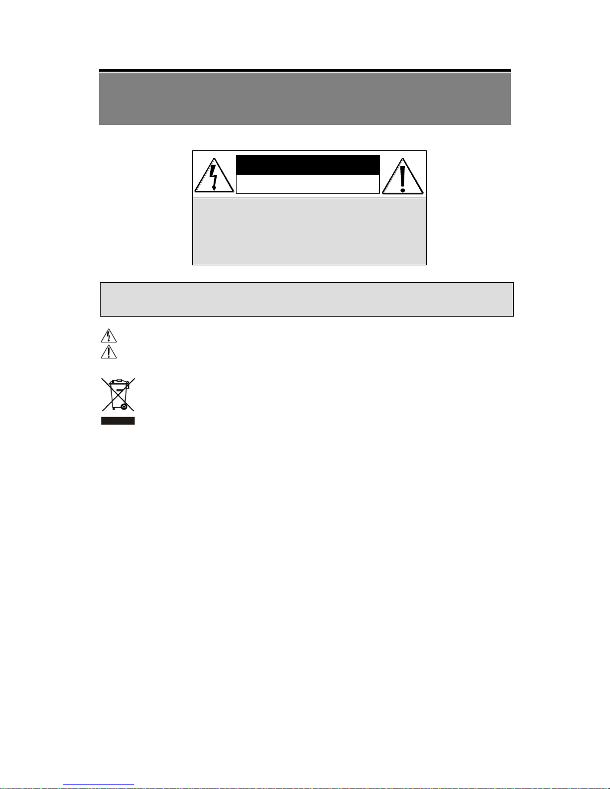
CAUTION
RISK OF EL EC TR IC SHOCK.
DO NOT OPEN !
CAUTIO N :
TO REDUCE THE RISK O F ELECTRICAL SHOCK,
DO NOT O PEN COVE RS (OR BAC K).
NO USER SERV ICEA BLE PARTS IN SIDE.
REFER SERVICIN G TO QUALIFIED
SERVICE PE RSONN EL .
WARNING: Alert the user to the presence of un-insulated “dangerous voltage”.
CAUTION: Alert the user the presence of important operating and maintenance (Servicing)
instructions in the literature accompanying the appliance.
Disposal of Old Electrical & Electronic Equipment (Applicable in the European
Union and other European countries with separate collection systems).
This symbol on the product or on its packaging indicates that this product shall not be
treated as household waste. Instead it shall be handed over to the applicable collection point
for the recycling of electrical and electronic equipment. By ensuring this product is disposed
of correctly, you will help prevent potential negative consequences for the environment and
human health, which could otherwise be caused by inappropriate waste handling of this
product. The recycling of materials will help to conserve natural resources. For more
detailed information about recycling of this product, please contact your local city office,
your household waste disposal service or the shop where you purchased the product.
Please be extra careful not to shake the product.
Please avoid places where frequent vibrations or shocks.
Do not install the product in extreme temperature conditions.
Only use the camera under conditions where temperatures are between -10℃ and +50℃. Be
especially careful to provide ventilation when operating under high temperatures.
Do not install the product in an environment where the humidity is high.
Unless the product is waterproof or weatherproof, otherwise it can cause the image quality to be
poor.
Never keep the product to direct strong light or sunlight.
It can damage the product.
Do not spill liquid of any kind on the product.
If it gets wet, wipe it dry immediately. Alcohol or beverage can contain minerals that corrode the
electronic components.
When any abnormal occurs, make sure to unplug the unit, and contact your local dealer.
It is advised to read the Safety Precaution Guide through carefully before operating the
product, to prevent any possible danger.
Page 4

4
2. INTRODUCTION
Clear image quality has been achieved by employing a 1/3” Hi-Res. CCD, which
provides a horizontal resolution of 700 TV lines. The camera can be by External Light
Sensor; it provides Color image in full light condition (Day) and provides B/W image in
low light condition (Night) to reach the best effect. High performance: providing unique
ATR (Adaptive Tone Reproduction) , DNR (Digital Noise Reduction), HLC (High Light
Compensation), CRS (Color Rolling Support), Privacy function, Mirror function, as well
as manually adjusting picture quality functions (Such as Contrast/Sharpness/Color etc.).
Page 5

5
3. FEATURES
High Resolution
Excellent Sensitivity
CCD Sensor provides high resolution
reaching 650~700 TVL with advanced
and clear picture quality.
High sensitivity, low smear, high
anti-blooming and high S/N ratio.
Adaptive Tone Reproduction (ATR)
Digital Noise Reduction (DNR)
ATR is the Single Scan WDR function;
it has the other name with Digital WDR,
Software WDR. perfectly shows the
image details between dark and light.
Newly added environment dynamic
detection switch, enhancing WDR
image efficiency.
With 2DNR enable, it can reduce the
noise to produce extremely clear picture
quality even under low light condition.
Day & Night
High Light Compensation (HLC)
Mechanic IR Cut-Filter driving unit
with Light Sensor.
By setting mask are, the user will
experience better operation convenience
see a clearer image.
Privacy Mask
Motion Detection
Privacy image masking with free
position, support up to 8 areas of
privacy masking zone.
Camera-site takes the initiative in
providing motion detection alert for a
more comprehensive monitoring and
careful editing of motion detection area.
When there are changes within the
detection area, the camera immediately
issues a warning.
Page 6

6
Lens (External manual focus)
OSD
Built-in DC-type Vari-Focal lens with
ICR / Without ICR.
OSD (On Screen Display) Setup Menu.
Camera tile setup of up to 16 alphanumeric
letters.
Mechanism
Weatherproofing Housing Design.
Application
All function can be operated from OSD: AES (Automatic Electronic Shutter), AI
(Auto Iris), GC (Gain Control), WB (White Balance), BLC (Back Light
compensation), positive/ negative and Horizontal Mirror.
Page 7
7
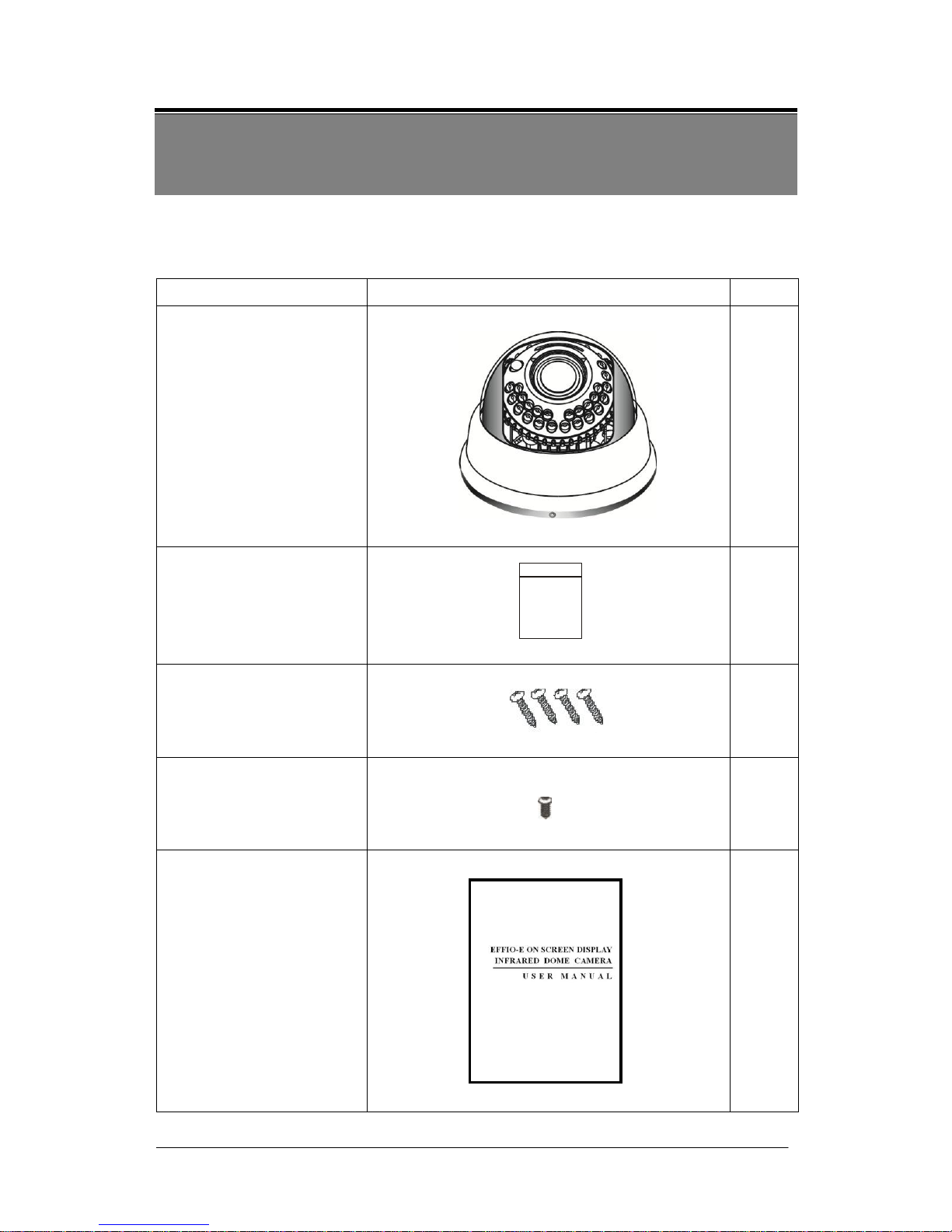
4. PACKING LIST
Check to make sure all of the items shown below are included in your product package.
If something is missing, contact your dealer as soon as possible.
Item Description
Item Picture
QTY
Camera & Bracket
1
Appurtenances
1
Fix retaining screw
4
Countersunk Head
Screws for Camera
Protection
1
Instruction Manual
1
Page 8
8
5. NAME and FUNCTION of EACH PART
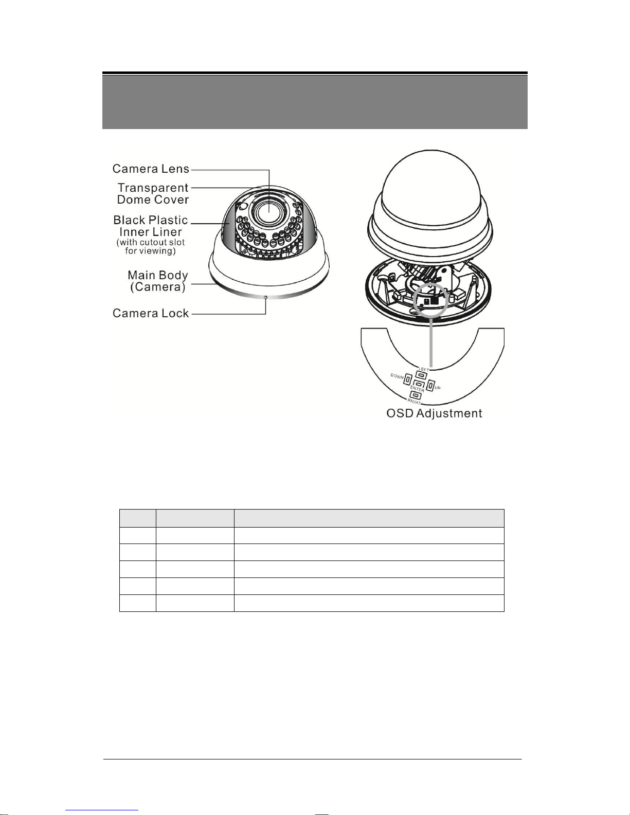
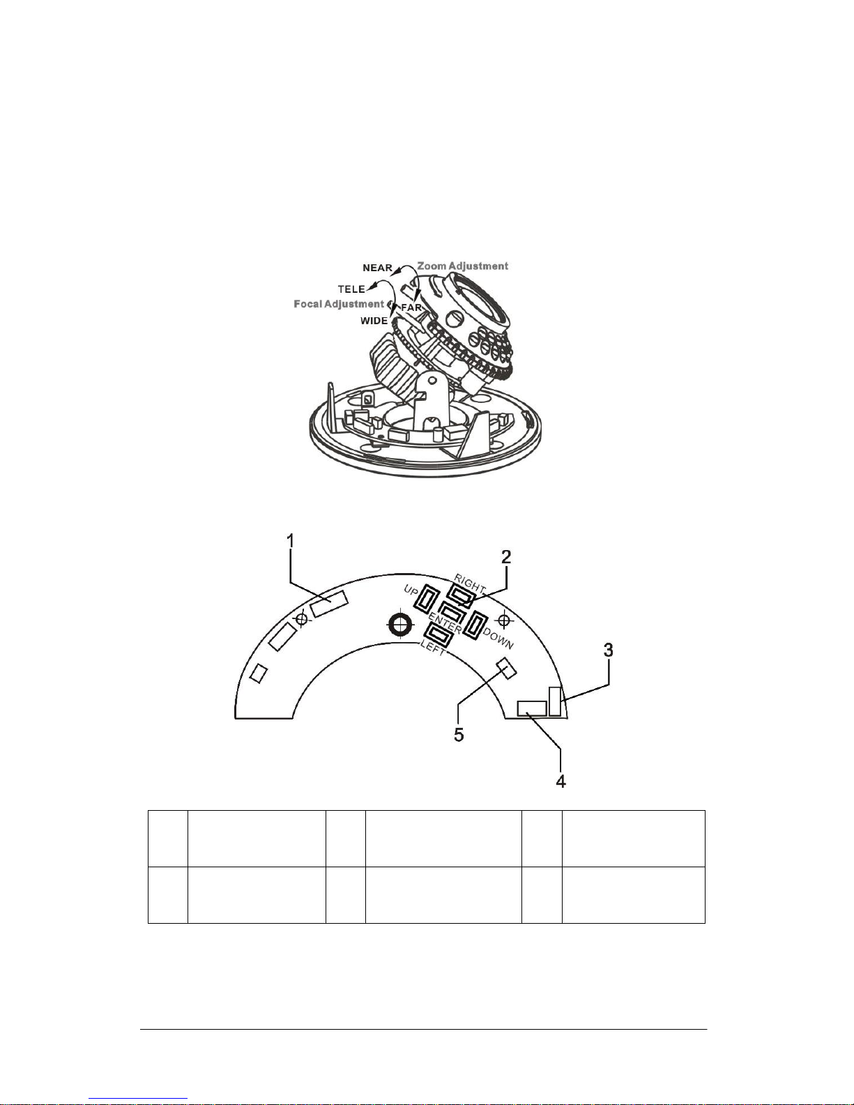
To adjust the OSD, remove the dome cover from the main body by gently turning the
cover counter-clockwise to unlock and pull free from the main body. The OSD
buttons are can be found on the main body of the dome camera.
1~3.OSD Button (Menu):
No.
Name
Function
1
LEFT
LEFT
2
ENTER
Get in MENU and ENTER
3
DOWN
DOWN
4
RIGHT
RIGHT
5
UP
UP
Page 9
9
6. INSTALLATION
6.1 Camera Installation & Operation
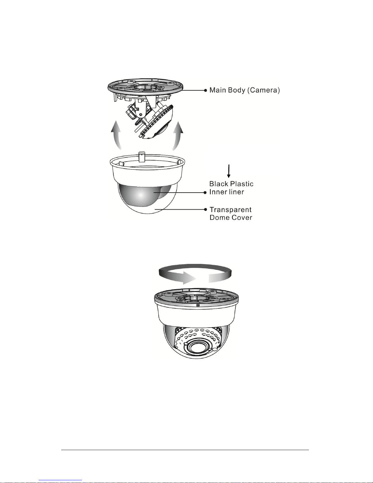
1. Removing the Dome Cover
Remove the dome cover from the main body by gently turning the cover
counter-clockwise to unlock and pull free from the main body.
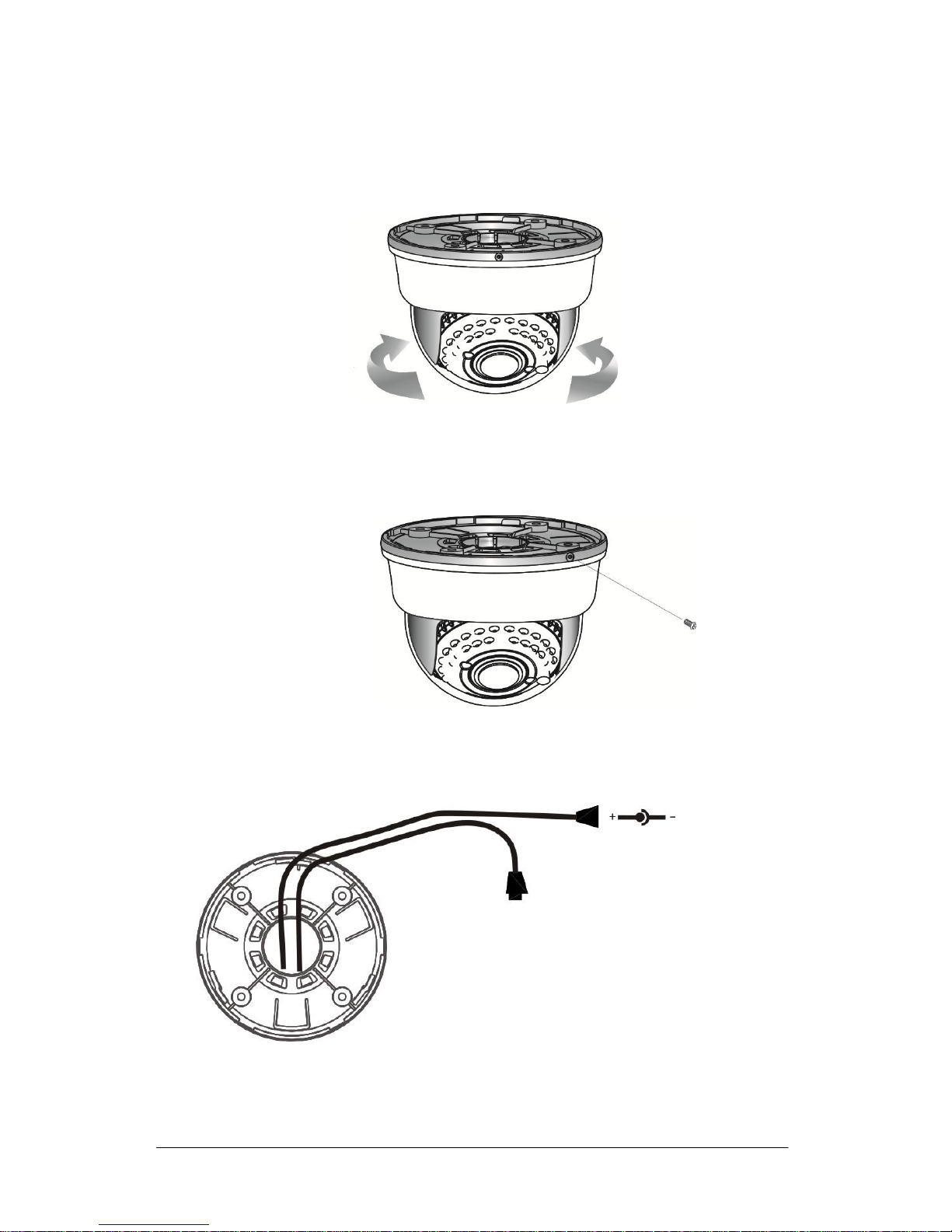
2. Camera Image Adjustment
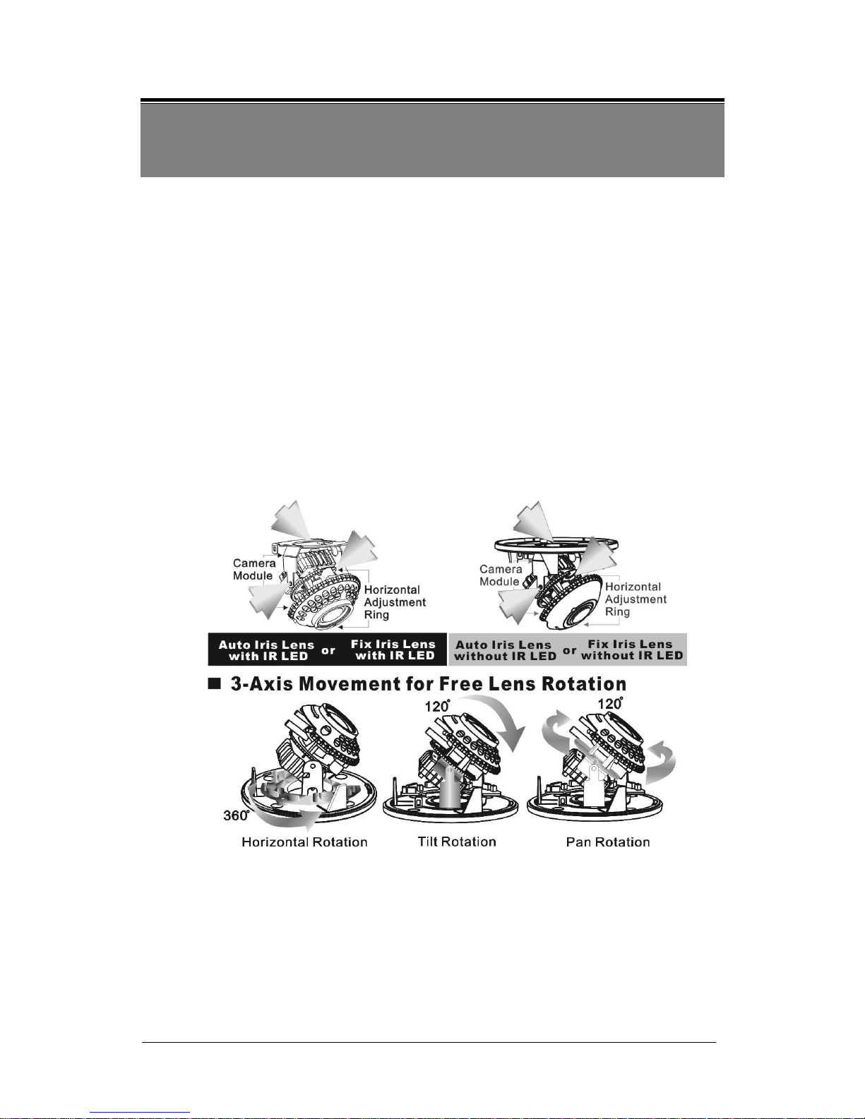
You can adjust camera to any direction by using Pan, Tilt, and Rotate
mechanism.
Pan Base moves by 60° to each side direction and 120° on the whole.
Tilt Base covers total 120° angle (60° to each side).
Angle range of Rotate Base is 360°.
Page 10
10
3. Adjusting the Vari-Focal Lens
Loosen the Zoom lever counter-clockwise a little, and then rotate the Zoom
lever to obtain the best image view.
Loosen the Focus lever counter-clockwise a little, and then rotate the Focus
lever to obtain the optimum picture quality.
Re-tighten the Zoom lever and Focus lever after adjustment.
4. Adjusting the Function Control Board
1
IR BOARD
WEFER
3
POWER/VIDEO
(CAMERA)
5
DAY IN
2
OSD KEY
4
POWER/VIDEO
(DC/BNC)
Page 11
11
5. Attaching the Dome Cover
After all necessary adjustment has been made reinstall the dome cover to the
main body.
Reinstall the dome cover and the main body by turning the dome clockwise
until it locks in place.
The black plastic inner liner
has a cutout slot for viewing.
Page 12
12
The dome comes with a black plastic inner liner placed within the dome cover.
Therefore, after replacing the dome cover rotate the liner so that the cutout slot
(hole for viewing) is in the correct position and not blocking the camera lens.
6. Camera Protection
To prevent unpredictable damage and burglary, lock-up the dome by using the
countersunk head screw.
7. Wiring Instructions
Connect the video output to the monitor or other video device through a 75 Ohms
type coaxial cable and the DC-Jack or AC/ DC-Terminator to the power source.
Note: Power adapter is sold separately.
Page 13

13
7. OPERATION
7.1 OSD Framework
Main Menu Display
OSD Setup Menu page 1
LENS
SHUTTER/ AGC
WHITE BAL
BACKLIGHT
ATR
NR
PICT ADJUST
NEXT↲
EXIT↲ SAVE ALL
AUTO↲
AUTO↲
ATW
OFF
OFF
↲
↲
OSD Setup Menu page 2
DAY/ NIGHT
PRIVACY
MOTION DET
CAMERA ID
LANGUAGE
CAMERA RESET
BACK↲
EXIT↲ SAVE ALL
AUTO*
OFF
OFF
OFF
ENGLISH
Main Menu Setup
In order to display the setup menu on the screen, set the menu command or press the
button panel.
Use UP/ DOWN control buttons to select each item.
Use LEFT/ RIGHT control buttons to change the data.
Use MENU control button to ENTER/ EXIT the menu display.
↲=ENTER
*NOTE: Item function DAY/ NIGHT of the IR LED dome having D/N external Sync
functions is auto disabled from the OSD display.
Page 14
14
7.2 OSD Main Menu Description
7.2.1 LENS: MANUAL /AUTO selectable.
LENS: MAUNAL
Not adjustment
LENS: AUTO
AUTO
TYPE:DC
MODE:AUTO/ OPEN /CLOSE
SPEED:000~255
AUTO: Camera automatically controls the lens.
OPEN: Lens fully open.
CLOSE: Lens fully closed.
SPEED: Speed of the lens.
7.2.2 SHUTTER/AGC: AUTO / MANUAL selectable.
SHUTTER/AGC: AUTO
AUTO
HIGH LUMINANCE
MODE:SHUT+AUTO IRIS / AUTO IRIS / SHUT
BRIGHTNESS:000~255
LOW LUMINANCE
MODE:AGC / OFF
BRIGHTNESS:x0.25、x0.50、x0.75、x1.00
HIGH LUMINANCE
When LENS is setup to AUTO mode
SHUT+AUTO IRIS: Exposure is controlled by auto electronic shutter combined
with auto iris.
AUTO IRIS: Exposure controlled by auto iris.
When LENS is setup to Manual mode
SHUT: Exposure controlled by electronic shutter.
LOW LUMINANCE
Setup low lux environment, minimum AGC level.
Page 15
15
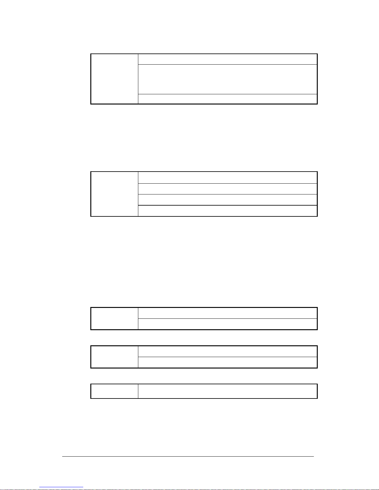
SHUTTER/AGC: MANUAL
MANUAL
MODE:SHUT+AGC
SHUTTER:
NTSC:1/60, 1/100, 1/250, 1/500, 1/1000, 1/2000, 1/4000, 1/10000
PAL:1/50, 1/120, 1/250, 1/500, 1/1000, 1/2000, 1/4000, 1/10000
AGC:6.00、12.00、18.00、24.00、30.00、36.00、42.00、44.80
SHUTTER: Fixed electronic shutter speed.
AGC: Fixed AGC gain control.
7.2.3 WHITE BAL
ATW / PUSH / USER1 / USER2 / ANTI CR / MANUAL / PUSH
LOCK selectable.
WHITE BAL.: ATW
ATW
SPEED:000~255
DELAY CNT:000~255
ATW FRAME:x0.50、x1.00、x1.50、x2.00
ENVIRONMENT:INDOOR、OUTDOOR
SPEED:ATW Speed
DELAY CNT: ATW Delay Time
ATW FRAME: ATW Frame Range Setup
ENVIRONMENT: ATW Environment Range Setup
WHITE BAL.: PUSH
The function will keep detecting the Color Temperature, and then it will
keep saving the parameter to camera.
WHITE BAL.: USER1
USER1
B-GAIN:000~255
R-GAIN:000~255
WHITE BAL.: USER2
USER2
B-GAIN:000~255
R-GAIN:000~255
WHITE BAL.: MANUAL
MANUAL
LEVEL:19~54
WHITE BAL.: ANTI CR
The function can reduce the color rolling issue, and it is the same with CRS
(Color Rolling Support) function.
WHITE BAL.: PUSH LOCK
The function will detect the Color Temperature to save into the camera.
Page 16
16
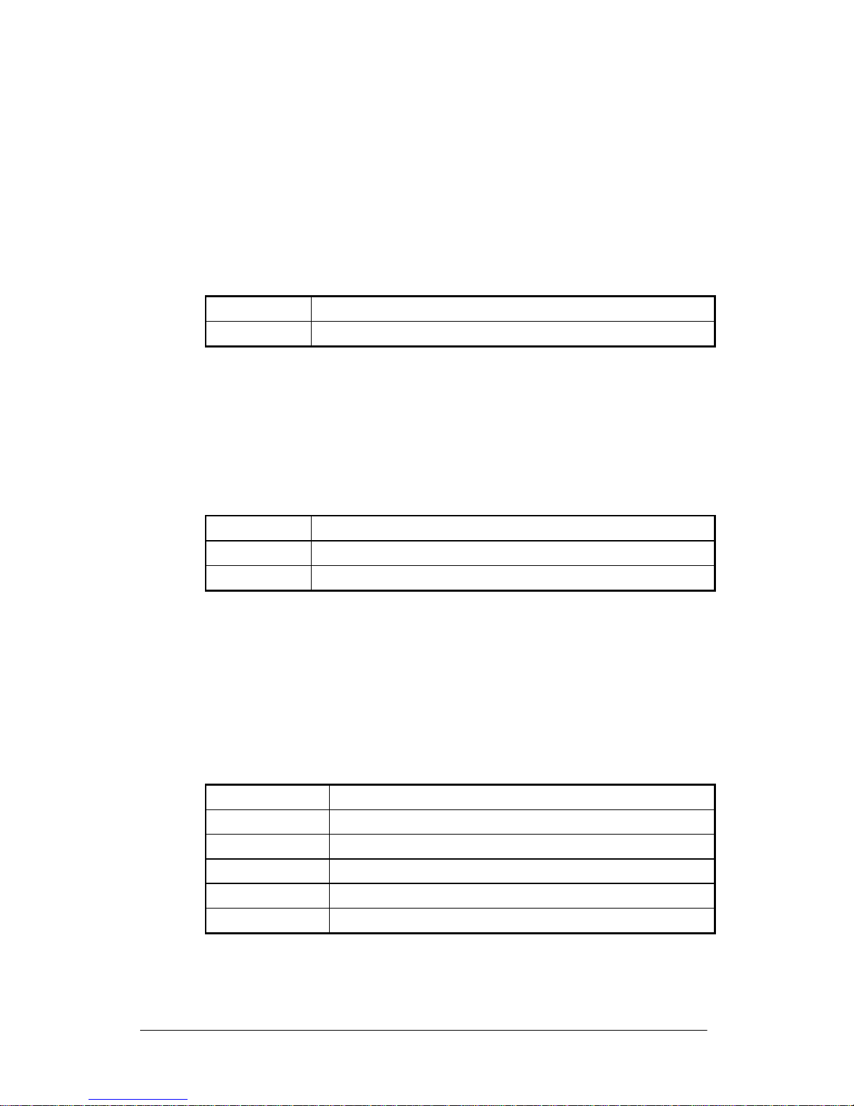
7.2.4 BACKLIGHT: BLC / HLC / OFF selectable.
BACKLIGHT.: BLC
Enable the function of Back Light Compensation, and the detection method
is the BLC Smart.
BACKLIGHT.: HLC
Enable the function of High Light Compensation.
7.2.5 ATR: ON / OFF selectable.
ATR.: ON
LUMINANCE
LOW、MID、HIGH
CONTRAST
LOW、MIDLOW、MID、MIDHIGH、HIGH
LUMINANCE: Set the extent of the luminance compression
CONTRAST: Set the extent of the contrast enhancement.
NOTE: If you enable the ATR funciton, please avoid to enable the BACKLIGHT
function in the same time.
7.2.6 NR: ↲
NR MODE
Y/C、Y、C、OFF
Y LEVEL
000~015
C LEVEL
000~015
NR MODE: Set the DNR mode of Y/C, Y and C.
Y LEVEL: Set the Y filter strength.
C LEVEL: Set the C filter strength.
NOTE: The Y/C mode is the automanic DNR mode.
7.2.7 PICT ADJUST: ↲
MIRROR
ON / OFF
BRIGHTNESS
000~255
CONTRAST
000~255
SHARPNESS
000~255
HUE
000~255
GAIN
000~255
Adjust all camera parameters here.
Page 17
17
7.2.8 NEXT: ↲
Move to MAIN MENU, page 2
7.2.9 EXIT: ↲
Exit OSD to choose the list.
7.2.10 SAVE ALL:
When you change the OSD menu settings, before leaving the OSD item option
SAVE ALL. Press ENTER key to change the memory settings for the OSD.
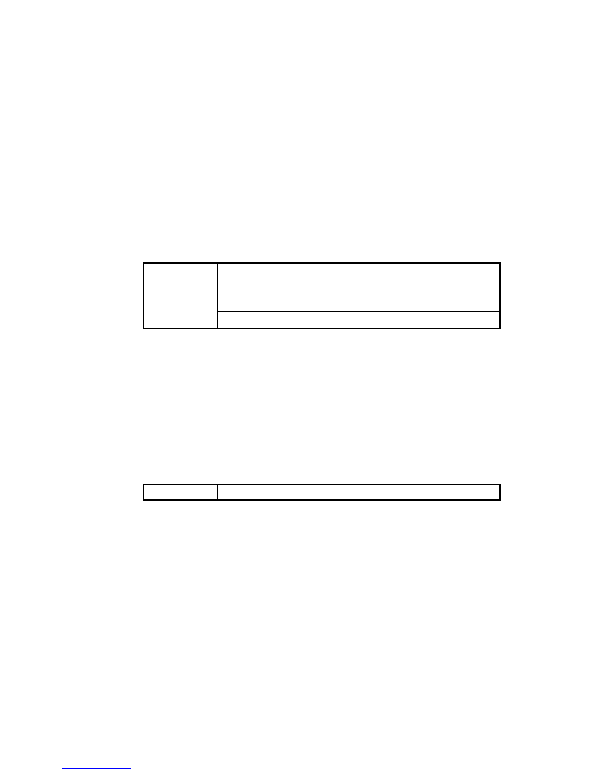
7.2.11 DAY/NIGHT:AUTO / DAY / B/W selectable.
DAY/NIGHT: AUTO
AUTO
BURST:ON/OFF
DELAY CNT:000~255
DAY NIGHT:000~255
NIGHT DAY:000~255
BURST:Selects whether to output the burst signal when the Night status
DELAY CNT:Set the Night/ Day identification transfer time.
DAY NIGHT:Set the threshold for identifying the Night status from the Day status.
NIGHT DAY:Set the threshold for identifying the Day status from the Night status.
DAY/NIGHT: DAY
Day mode forcibly
DAY/NIGHT: NIGHT
Night mode forcibly
Night
BURST:ON/OFF
BURST:Selects whether to output the burst signal
Page 18

18
7.2.12 PRIVACY: ON / OFF selectable.
PRIVACY: ON
AREA SEL
Max. 8
TOP
000~244 (NTSC) / 000~288(PAL)
BOTTOM
000~244 (NTSC) / 000~288(PAL)
LEFT
550TVL:000~378 (NTSC)、000~370 (PAL)
650TVL:000~474 (NTSC)、000~468 (PAL)
RIGHT
550TVL:000~378 (NTSC)、000~370 (PAL)
650TVL:000~474 (NTSC)、000~468 (PAL)
COLOR
1~8
TRANSP
0.00 / 0.50 / 0.75 / 1.00
MOSAIC
ON / OFF
AREA SEL: Select the mask frame to be adjusted.
NOTE: When the MONITOR AREA has been set to ON by the MOTION
DET setting, only 4 PRIVACY AREA SEL are selectable (1 / 4, 2 / 4,
3 / 4, 4 / 4).
TOP: Set the top side of the mask frame selected
BOTTOM: Set the bottom side of the mask frame selected
LEFT: Set the left side of the mask frame selected
RIGHT: Set the right side of the mask frame selected
COLOR: Set the colors of the mask frames.
TRANSP: Set the transparency ratio of the mask frames.
MOSAIC: Set the mask frame mosaic function to ON or OFF.
Page 19
19
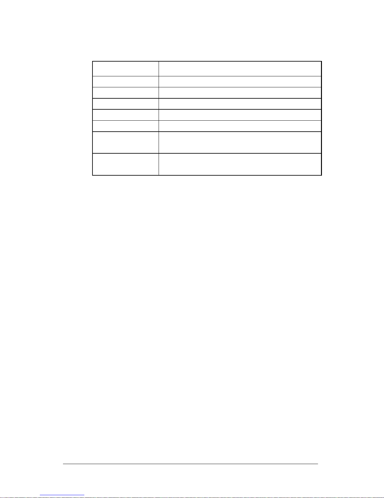
7.2.13 MOTION: ON / OFF selectable.
MOTION DET: ON
DETECT SENSE
000~127
BLOCK DISP
ON / OFF / ENABLE
MONITOR AREA
ON / OFF
AREA SEL
1~4
TOP
000~244 (NTSC) / 000~288(PAL)
BOTTOM
000~244 (NTSC) / 000~288(PAL)
LEFT
550TVL:000~378 (NTSC)、000~370 (PAL)
650TVL:000~474 (NTSC)、000~468 (PAL)
RIGHT
550TVL:000~378 (NTSC)、000~370 (PAL)
650TVL:000~474 (NTSC)、000~468 (PAL)
DETECT SENSE: Set the motion detection sensitivity.
BLOCK DISP: Control the ON/ OFF status of the motion detection block
display.
MONITOR AREA: Set whether to use the monitoring frames.
AREA SEL: Select the monitoring frame to be set.
TOP: Set the top side of the monitoring frame selected
BOTTOM: Set the bottom side of the monitoring frame selected
LEFT: Set the left side of the monitoring frame selected
RIGHT: Set the right side of the monitoring frame selected
Page 20
20
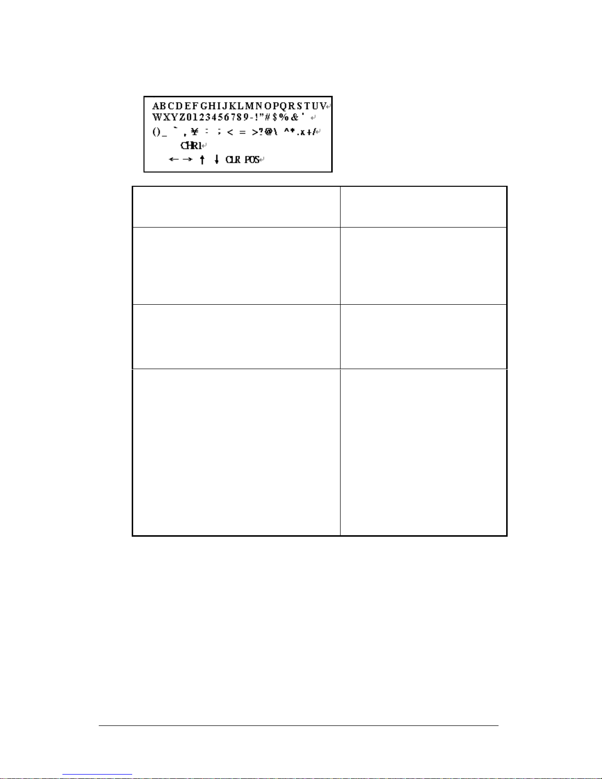
7.2.14 CAMERA ID: ON / OFF selectable.
A B C D E F G H I J K L M N O P Q R S T U V
W X Y Z 0 1 2 3 4 5 6 7 8 9 - ! ” # $ % & ’
( ) _ ‵ , ¥ : ; < = > ? @ \ ^ * . x + /
Each User Font
← → ↑ ↓
The camera ID cursor moves in the
direction of the arrow when the Enter
operation input is performed from the
status in which ←, →, ↑ or ↓ has been
selected using the character selection
cursor.
CLR
The character selected by the camera ID
cursor is cleared when the Enter
operation input is performed from the
status in which CLR has been selected
using the character selection cursor.
POS
The display switches to the camera ID
display position setting screen when the
Enter operation input is performed from
the status in which POS has been
selected using the character selection
cursor. On the camera ID display
position setting screen, the camera ID
display position is changed in real time in
response to the left, right, up or down
operation input. When the Enter
operation input is performed, the display
position is entered, and the display
returns to the camera ID setting screen.
7.2.15 LANGUAGE
There are 8 kind of language: English / Japanese / German / French / Russian /
Portuguese / Spanish / Simplified Chinese selectable.
7.2.16 CAMERA RESET
Reset Factory default setup.
7.2.17 BACK
Return to MAIN MENU, page1.
Page 21
21
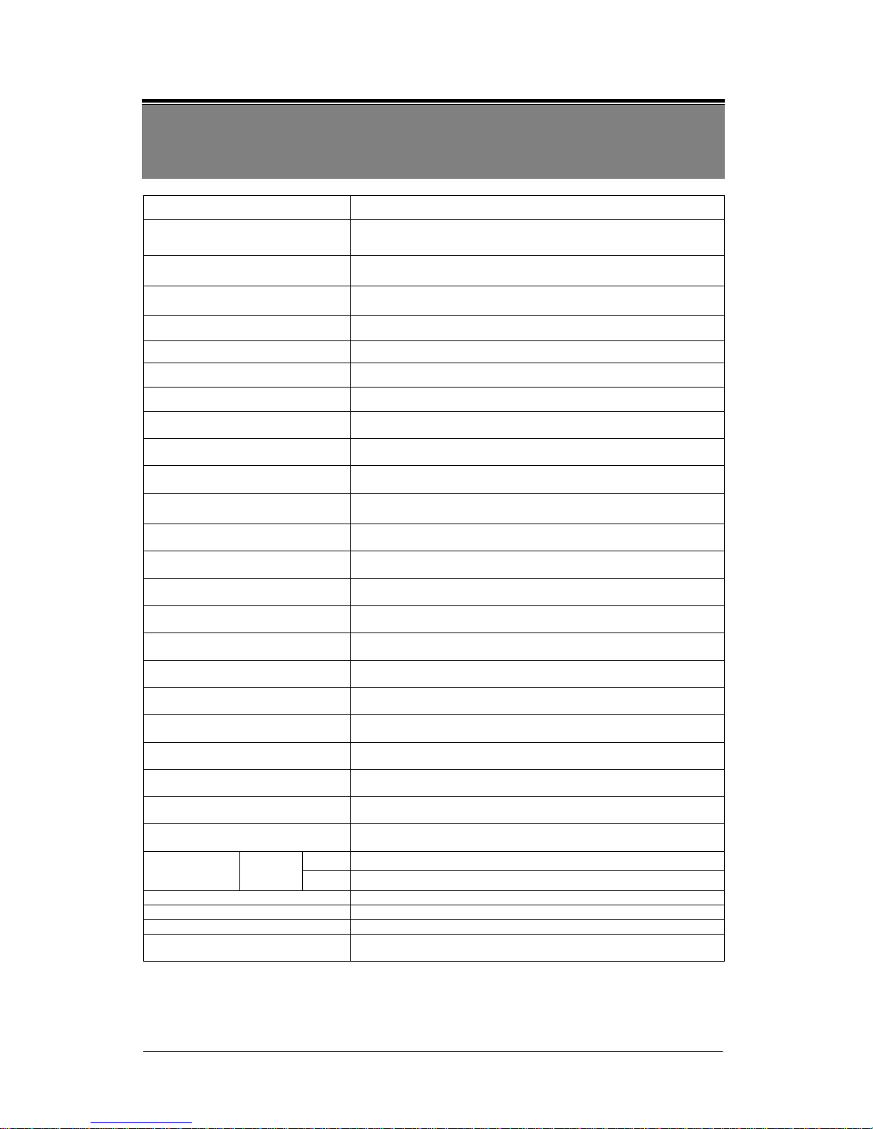
8. SPECIFICATION
Note: Design and specifications are subject to change without prior notice.
Model no.
EYD105VDR
Image Device
1/3” Color CCD Ex-View HAD II
(Sony Chipset)
Effective Picture Elements
NTSC: 976x494
PAL: 976x582
Horizontal Resolution
700TVL
Minimum Illumination
0.01ux/ F1.2
Day to Night Illumination
Under 5 Lux
S/N Ratio
More than 48dB (AGC OFF)
Shutter Speed Control
NTSC:1/60~1/100,000, PAL:1/50~1/100,000
Lens Furnished
Vari-Focal Lens with ICR
Auto Iris Control
DC Driver
Gain Control
Auto/ Manual
White Balance
ATW / PUSH / USER1 / USER2 / ANTI CR / Manual / PUSH LOCK
ATR
ON/ OFF
DNR
ON/ OFF
Back Light Compensation
ON/ OFF
High Light Compensation
ON/ OFF
IR Optimizer
ON/ OFF
PRIVACY
Maximum 8 Areas
MOTION DET
4 Areas
Camera ID
Up to 52 Characters
Mirror
ON/ OFF
Positive/ Negative
ON/OFF
Video Output
1Vp-p/ 75 Ohms
Power Supply
DC 12V±10%
Power
Consumption
Vari-Focal
Lens+IR
IR On
370mA max.
IR Off
120mA max.
Operating Temp.
-10℃ ~ 50 ℃ (14 to 122℉)
Gamma Characteristic
0.45
Synchronous System
INT
Dimensions (WxD)
32 mm x32 mm (Camera board)
37 mm x35 mm (OSD board)
Page 22

22
MEMO
 Loading...