

Page 1
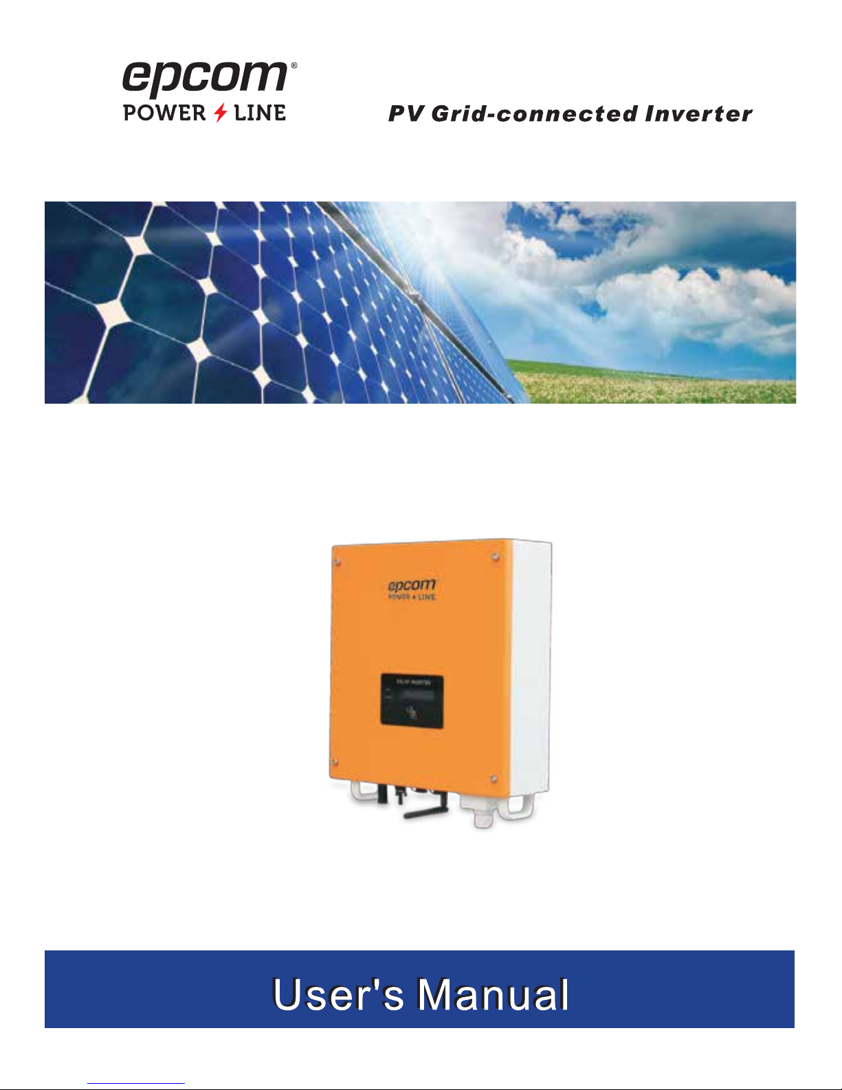
EPIG1K / EPIG2K
Page 2

Contents
1. Manual Instruction
1.1 Symbols used in this manual ........................................................................................................ 1
1.2 User group ................................................................................................................................... 2
1.3 Validity ......................................................................................................................................... 2
2. Safety Instructions
2.1 Intended use ................................................................................................................................ 2
2.2 Safety instructions ........................................................................................................................ 3
3. Unpacking
3.1 Scope of delivery .......................................................................................................................... 4
3.2 Identifying the Inverter .................................................................................................................. 4
4. Mounting the Device
4.1 Security ........................................................................................................................................ 5
4.2 Selecting the mounting location .................................................................................................... 5
4.3 Mounting instructions .................................................................................................................... 7
5. Electrical Connection
5.1 Connection Area Overview ........................................................................................................... 9
5.2 System Diagram ......................................................................................................................... 10
5.3 Cable Sizing ............................................................................................................................... 11
5.4 Connection of the PV generator (DC) .......................................................................................... 12
5.5 Connecting the inverter to the grid .............................................................................................. 13
5.6 Connecting communication cable ............................................................................................... 16
6. Switch on and off
6.1 Switch on ................................................................................................................................... 17
6.2 Switch off ................................................................................................................................... 17
7. Operation
7.1 Display Overview ........................................................................................................................ 18
7.2 LED display ................................................................................................................................ 18
7.3 LCD display ................................................................................................................................ 19
8. Troubleshooting
8.1 Display Message ................................................................................................ ........................ 23
9. Technical data ...................................................................................................................... 29
10. Appendix
10.1 Exclusion of liability................................................................................................................... 31
Page 3
<<1
1. Manual Instruction
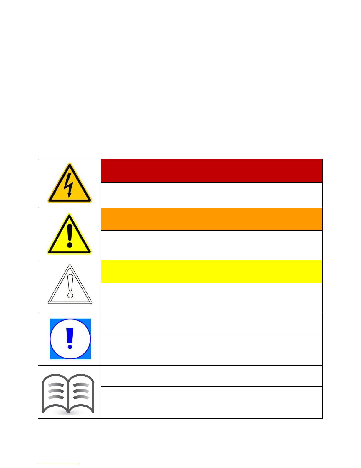
1.1 Symbols used in this manual
This manual contains important instructions for safety and operation which must be
understood and carefully followed during installation and maintenance of the equipment.
In order to reduce the risk of electric shock and to be sure that the equipment is correctly
installed and ready to operate, special safety symbols are used in the manual to highlight
potential safety risks or useful information. The symbols are the following:
DANGER!
DANGER indicates a hazardous situation which, if not avoided,
will result in death or serious injury.
WARNING!
WARNING indicates a hazardous situation which, if not avoided,
could result in death or serious injury.
CAUTION!
CAUTION indicates a hazardous situation which, if not avoided,
could result in minor or moderate injury.
NOTICE
NOTICE indicates a situation which, if not avoided, could result
in property damage.
Information
Information provides tips that are valuable for the optimal
installation and operation of your product.
Page 4
2>>
1.2 User group
This manual is for electrically skilled persons. The tasks described in this manual may
only be performed by electrically skilled persons.
1.3 Validity
This manual applies to EPIG1K / EPIG2K dirg
-
connected inverter and
describes the mounting, installation, commissioning, maintenance and troubleshooting
procedures.
Keep this manual in a convenient place for future reference.
2. Safety Instructions
2.1 Intended use
EPIG1K / EPIG2 is a PV inverter; which converts the direct current of the
PV array to grid-compliant alternating current and feeds it into the power distribution grid.
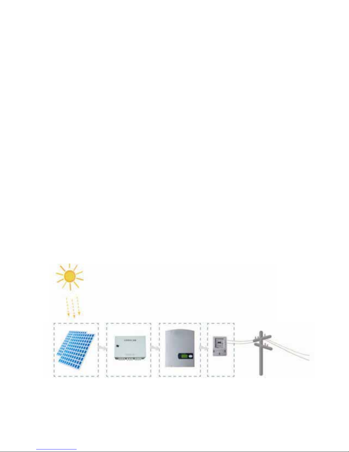
PV grid-connected system consists of PV modules, grid-connected inverters, metering
device and power distribution system (Figure 1).
Figure 1 PV grid-connected system
PV modules
Combiner box
Inverter
Metering
Power grid
Page 5
<<3
The EPIG1K / EPIG2K retrevni seirSe is suitable for indoor and outdoor
use and may only be operated with PV arrays (PV modules and cabling) of protection
class II... Do not connect any sources of energy other than PV modules to the inverter.
Any other use can result in personal injury or property damage.
2.2 Safety instructions
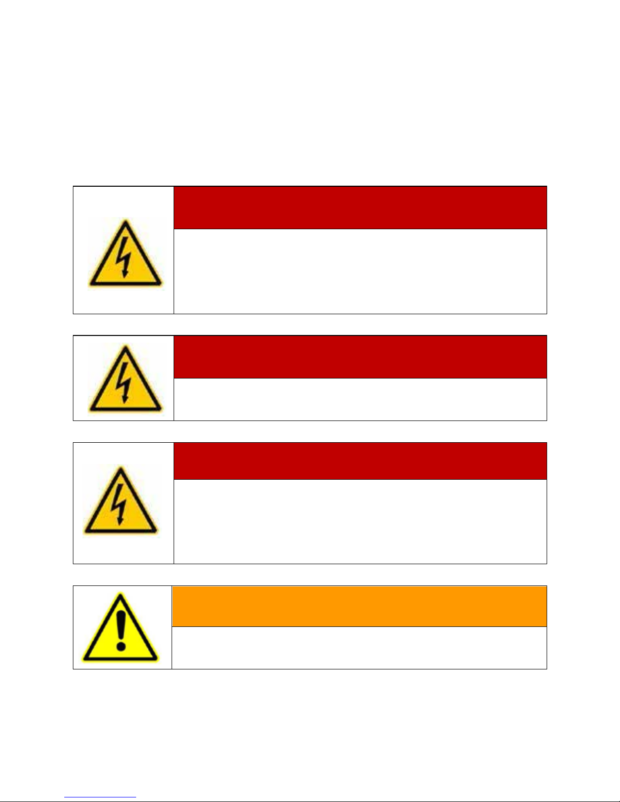
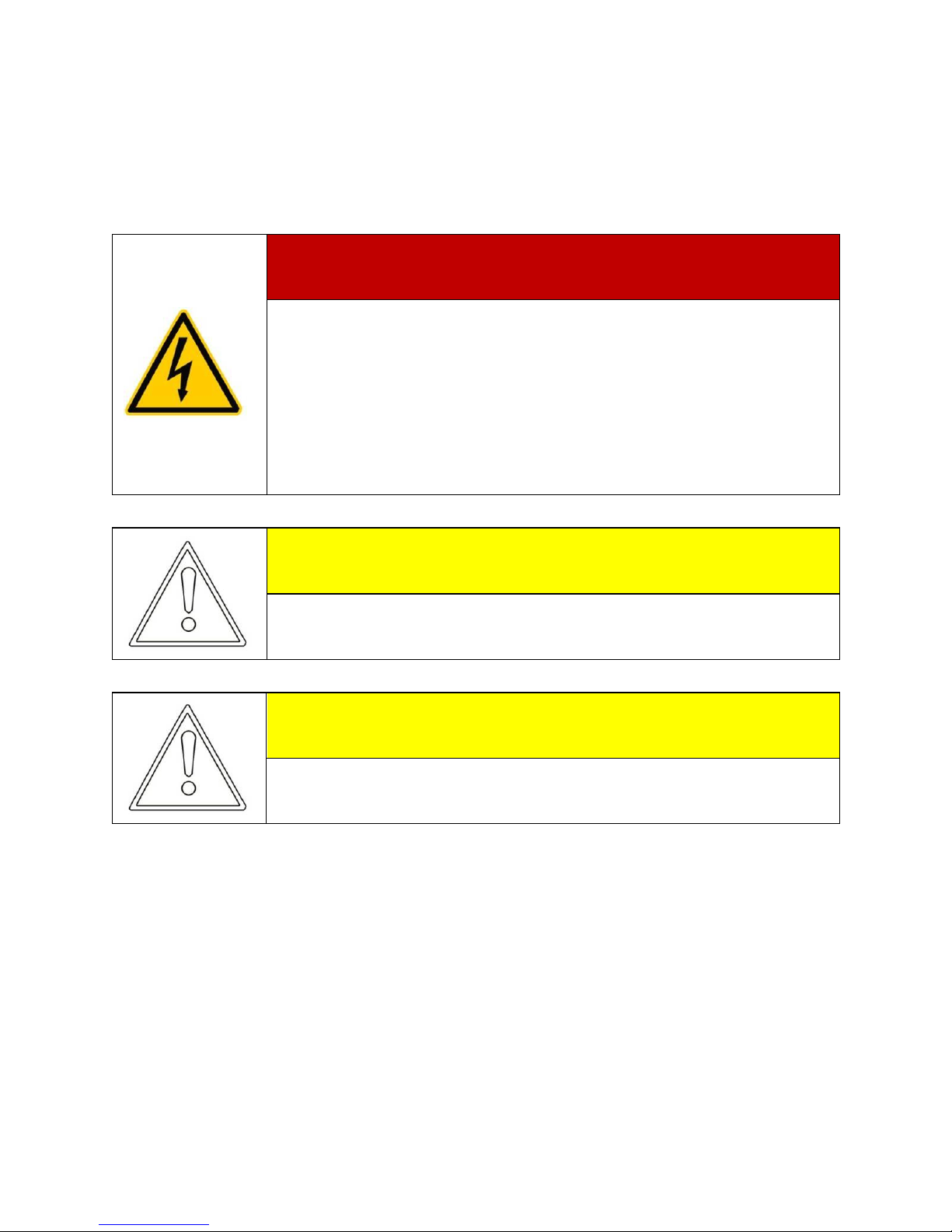
DANGER!
Danger to life due to high voltages in the inverter!
High voltages that can result in electrical shocks are present in the
conductive component parts of the inverter.
All work on the inverter may be carried out by qualified personnel
only.
DANGER!
Danger of burn injuries due to hot enclosure parts.
Do not touch enclosure during operation.
Only touch the lid during operation.
DANGER!
Before opening the housing, the inverter must be disconnected
from the grid and PV generator; while you must wait at least 5
minutes to let the energy storage capacitors fully discharged after
disconnecting from the power sources.
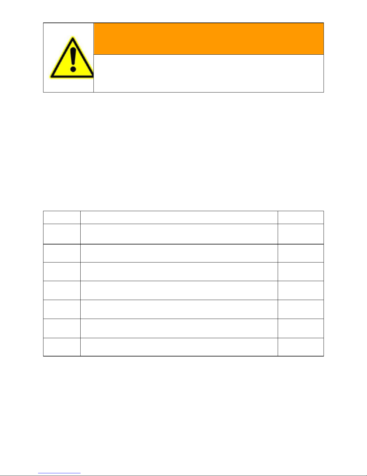
WARNING!
The installation must be performed in full compliance with
national and local standards and regulations.
Page 6
4>>
WARNING!
Grounding the PV Generator
Be sure that the PV generator frame and inverter connect to the
ground in order to achieve maximum protection of the system and
personnel
3. Unpacking
3.1 Scope of delivery
Check the delivery for completeness and for any visible external damage. Contact your
dealer if anything is damaged or missing.
Object
Description
Quantity
A
EPIG1K / EPIG2K inverter
1
B DC plug connectors (1 x positive/1 x negative) 1 pair
C AC plug assembly 1
D Wall plug 4
E
Mounting screws
4
F
Mating connector for RS485 terminal block
2
G User manual 1
3.2 Identifying the Inverter
You can identify the inverter by the type label. The type label is on the right side of
the enclosure. The serial number (Serial No.) and the type (Type / Model) of the product,
as well as device-specific characteristics are specified on the type label.
Page 7
<<5
4. Mounting the Device
4.1 Security
DANGER!
Danger to life due to fire or explosion!
• Despite careful construction, electrical devices can
cause fires.
• Do not mount the inverter on flammable construction materials.
• Do not install the inverter in areas where highly
flammable materials are stored.
• Do not install inverters in areas with a risk of explosion.
CAUTION!
Risk of injury due to the heavy weight of the inverter.
• Take the weight of the inverter into account for transport.
• Select a suitable mounting location and mounting surface.
CAUTION!
Danger of burn injuries due to hot enclosure parts!
Mount the inverter in such a way that it cannot be touched
inadvertently.
4.2 Selecting the mounting location
Consider the following requirements when selecting the mounting location:
The mounting method and location must be suitable for the inverter's weight
and dimensions (see section 11 "Technical Data" (page 80)).
Mount on a solid surface.
The mounting location must at all times be clear and safely accessible.
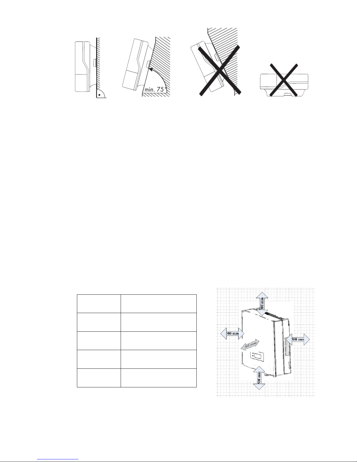
Mount vertically or tilted backwards by max. 15°.
Page 8
6>>
The connection area must point downward.
Never mount the device with a forward tilt...
Never install the device with a sideways tilt.
Do not mount horizontally...
Mount at eye level to allow operating states to be read at all times.
The ambient temperature should be below 40°C to ensure optimum operation.
Do not expose the inverter to direct sunlight as this can cause excessive
heating and thus power reduction.
In living areas, do not mount the unit on plasterboard walls or similar to avoid
audible vibrations. When in use, the inverter emits noises which may be
perceived as a nuisance in a living area.
Observe the following minimum clearances to walls, other devices or objects
to guarantee sufficient heat dissipation and enough space for pulling the
Electronic Solar Switch handle.
Direction
Minimum clearance
Sides
300 mm
Above
300 mm
Below
500 mm
Front
50 mm
Page 9
<<7
4.3 Mounting instructions
Mounting procedures:
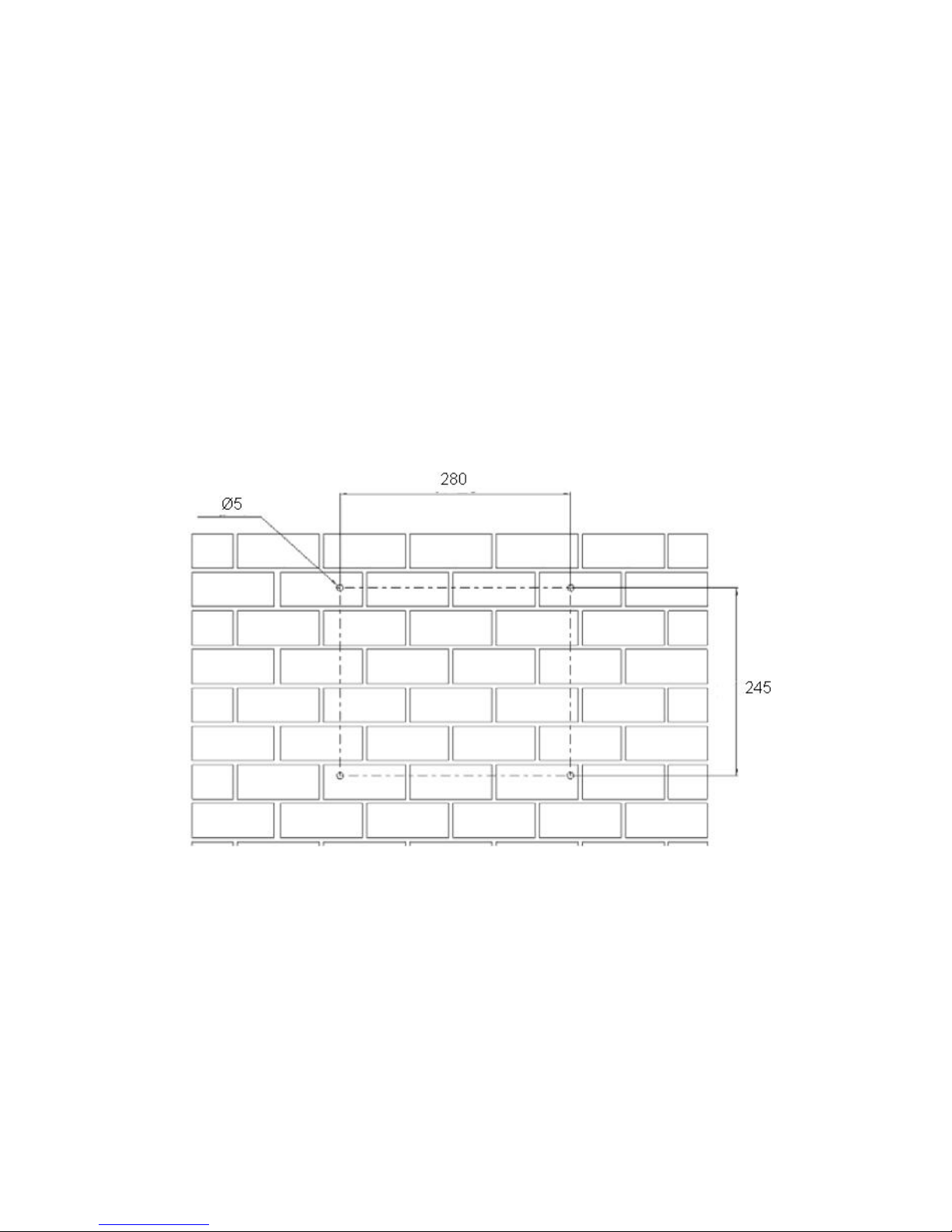
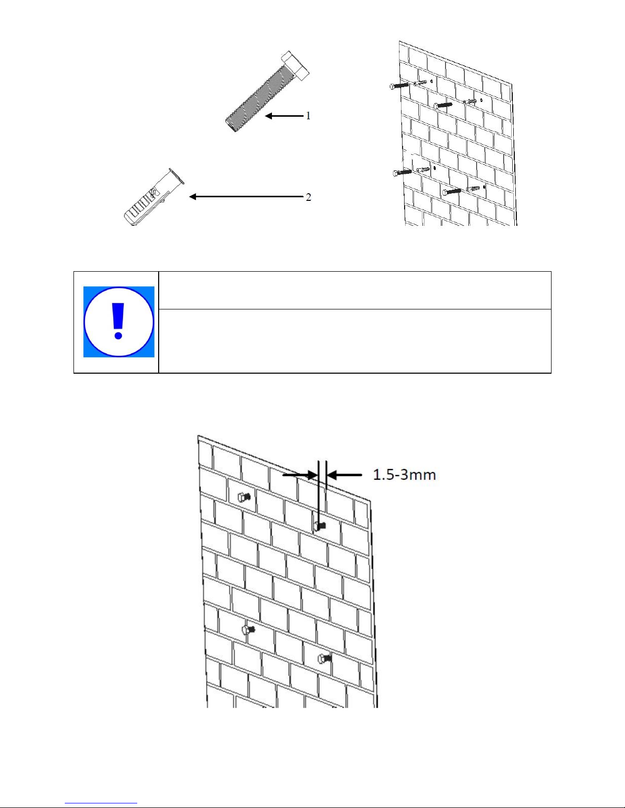
a) Drilling holes:
There are holes on the mounting template in the accessory, which is for help of
orientation. Drill four holes for the screws at the selected installation position. The space
between every two holes is shown in the figure below. Keep drilling vertical to the wall
and don’t shake the drill to avoid holes tilting. The depth of the holes must be the same
and 55mm~60mm. After removing the dust in the four holes, measure the net depth of
the holes. If the depth is deeper than 60 mm or less than 55 mm, the wall plugs wouldn’t
be installed and tightened.
b) Wiring the screws
After drilling holes in the wall, place four wall plugs (object2 shown in the left drawing
below) in the holes using a rubber hammer. Then, wiring four screws (object1) into the
wall plugs.
Page 10
8>>
NOTICE
Before inserting wall plugs, measure the depth of every hole and
the distance between every two holes. If the measured values do
not meet the installing requirements, re-drill holes in the wall.
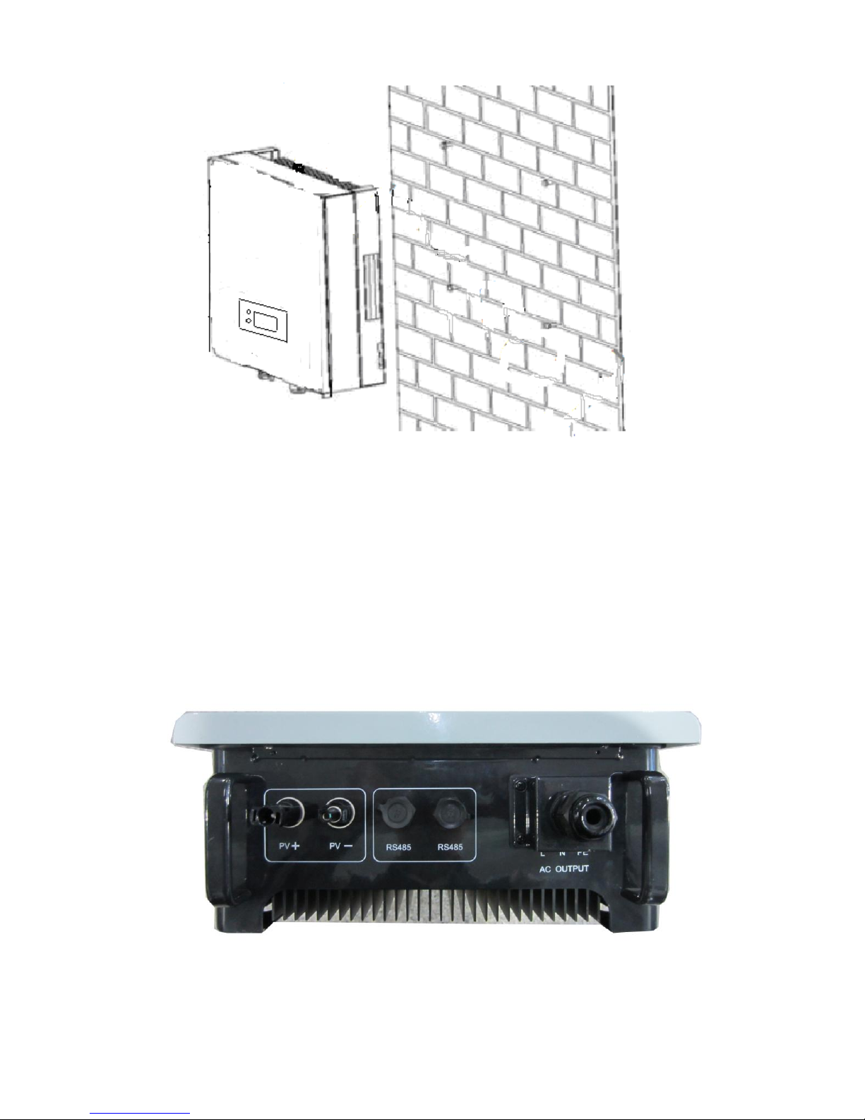
c) Attach the inverter to the screws downwards slightly.
Page 11
<<9
5. Electrical Connection
5.1 Connection Area Overview
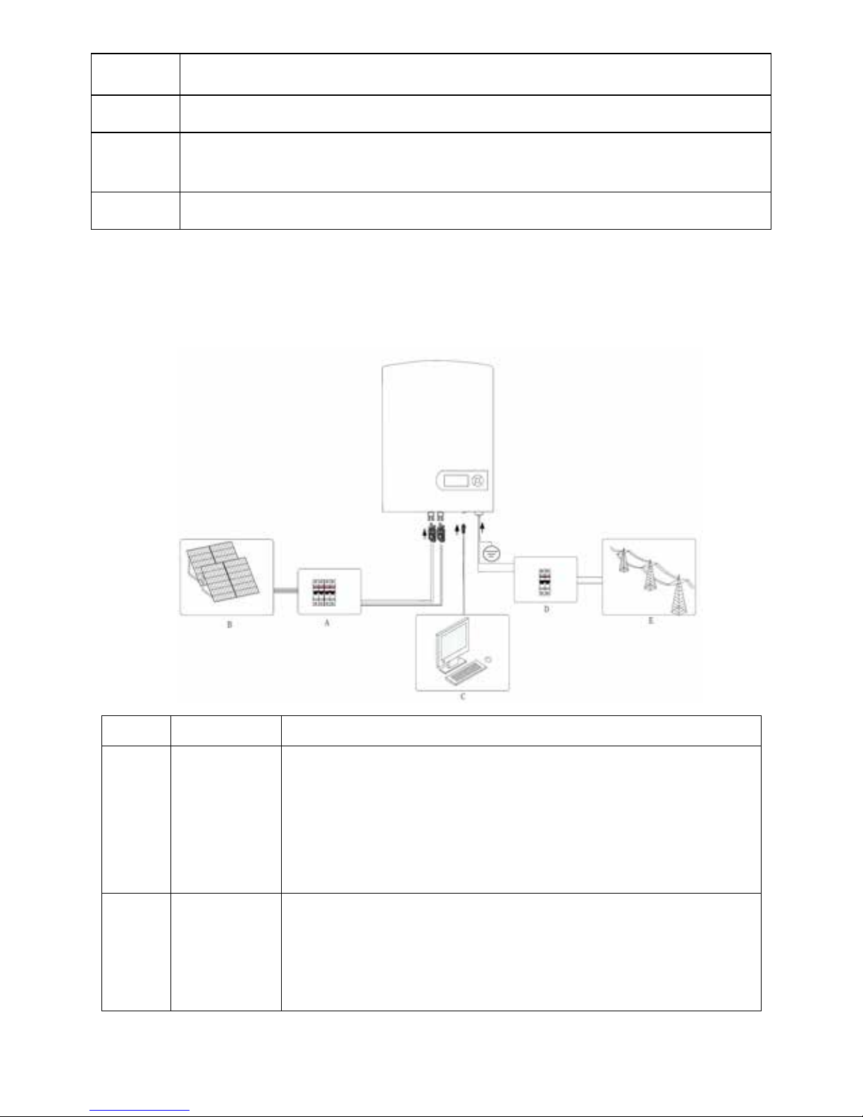
The following figure shows the assignment of the individual connection areas on the
bottom of the inverter.
A B C
Page 12
10>>
Object Description
A DC input: Plug-in connectors for connecting the PV strings
B
Communication connection area: PV inverters are configured via RS485
interface.
C AC output: Socket for grid connection
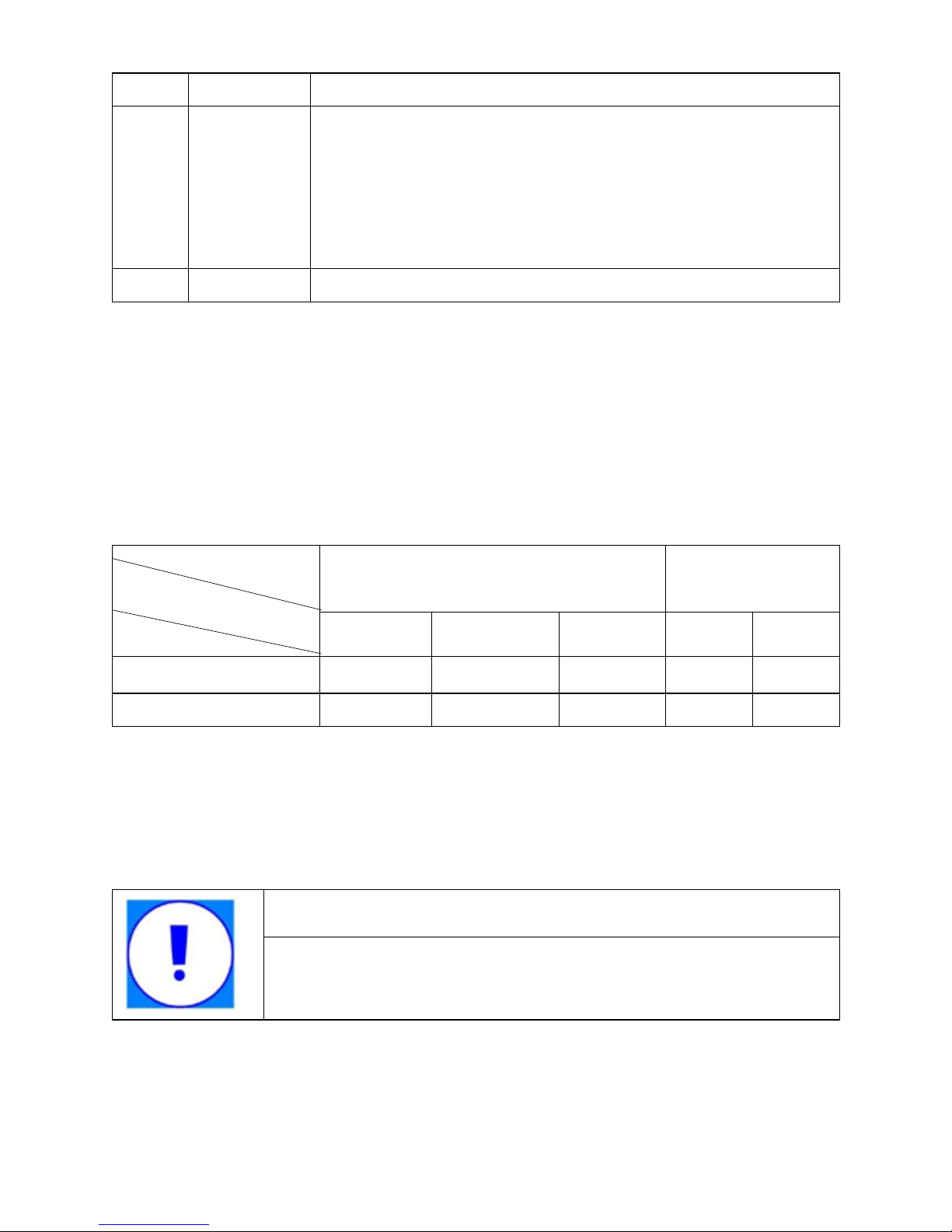
5.2 System Diagram
The typical connection diagram for the entire PV system is shown in the following figure.
Object Item Description
A
DC circuit
breaker
Used as a protective device during electrical connection. User
must equips this device according to the maximum input
voltage and current. You must choose the external DC circuit
breaker whose rated current is 20A and the max breaking
capacity can reach more than 1kA.
B PV arrays
Provide DC power to the inverter. The allowable maximum
open-circuit voltage of the PV arrays is 550V and maximum
short-circuit currents 13.5A for EPIG1K /
15.5A for EPIG2K
Page 13
<<11
C Remote PC User equips this device to monitor the state of the inverter.
D
AC circuit
breaker
Used as a protective device during electrical connection. You
must choose the external AC circuit breaker whose rated
current is 20A and the max breaking capacity can reach more
than 2kA. The PE cable should be connected reliably to the
earth.
E Grid Rated voltage of the utility grid is 230V.
5.3 Cable Sizing
All cables for PV power system are equipped with water-proof direct plug-in connectors.
You‘ll nd t hese connectors in the package
For electrical connection in the PV system described above, the cross section of all
cables used should not be smaller than the following requirements.
AC Output DC Input
L N PE + -
EPIG1K 14 14 14 12 12
EPIG2K
12 12 12 11 11
There is only one channel of DC input which can connect one PV string. The red is
“+”, and the black is “ -”. There is one c hannel of AC output, the red is L phase, the black
is N phase,and the yellow-green is PE.
NOTICE
The grid impedance of the AC cable must not exceed 1 Ohm. Otherwise, the
inverter will disconnect at full feed capacity due to excessive voltage at the feed-
in point.
Wire Size
AWG
Model
Terminal
Page 14
12>>
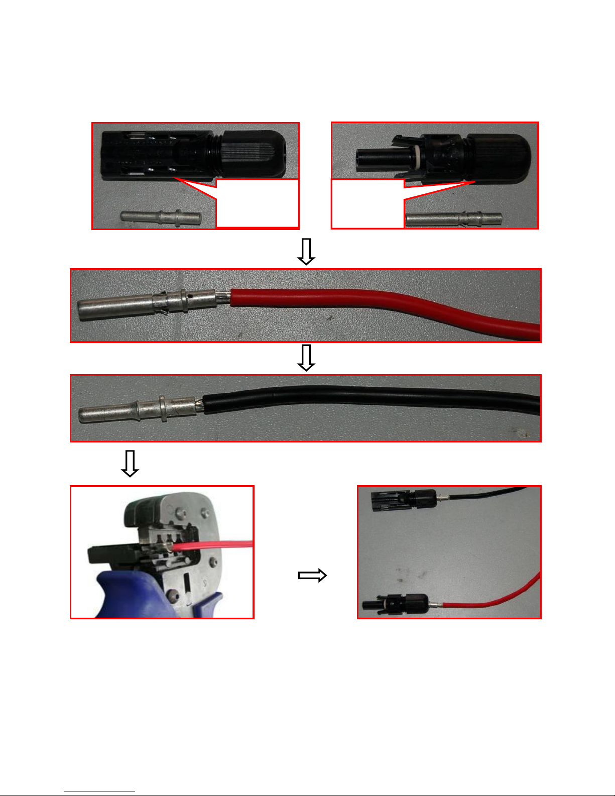
5.4 Connection of the PV generator (DC)
5.4.1 DC input wiring
5.4.2 DC connection Procedure
Step 1: Assemble DC cable to connector at the inverter side. See “5.4.1 DC Input
Wiring”.
Step 2: Disconnect DC and AC circuit breakers.
Negative
terminal
Positive
terminal
Page 15
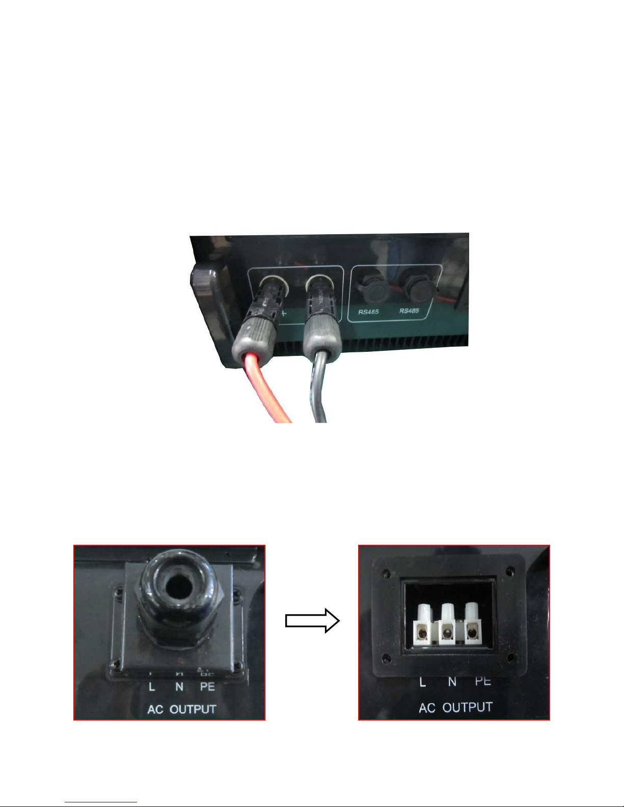
<<13
Step 3: Check connection cable of one PV array string for correct polarity and that the
maximum input open circuit voltage does not exceed 450V.
Step 4: Measure DC voltage between positive terminal of the PV string and Earth and
DC voltage between negative terminal of the PV string and Earth. If the two
voltages are constant and not zero, there is an insulation failure somewhere in
this PV string.
Step 5: Plug DC positive and negative connector into corresponding terminals. If it
makes a click sound, it means DC connector has attached to terminals.
5.5 Connecting the inverter to the grid
5.5.1 AC output wiring
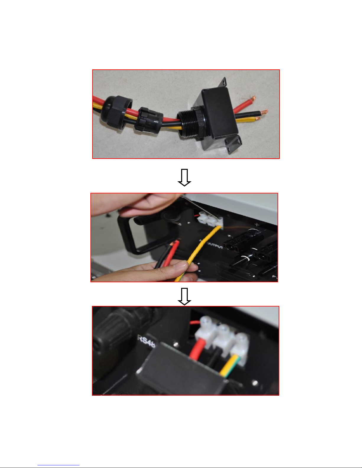
Step 1: Unscrew AC output cover at the downside of the machine.
Page 16
14>>
Step 2: Insert stripped AC cables of appropriate size into the cable glands. Fix the phase
cables into corresponding terminals with screwdriver according to marks. Fix ground
cable into the ground terminal.
Step 3: Screw the AC output cover.
Page 17
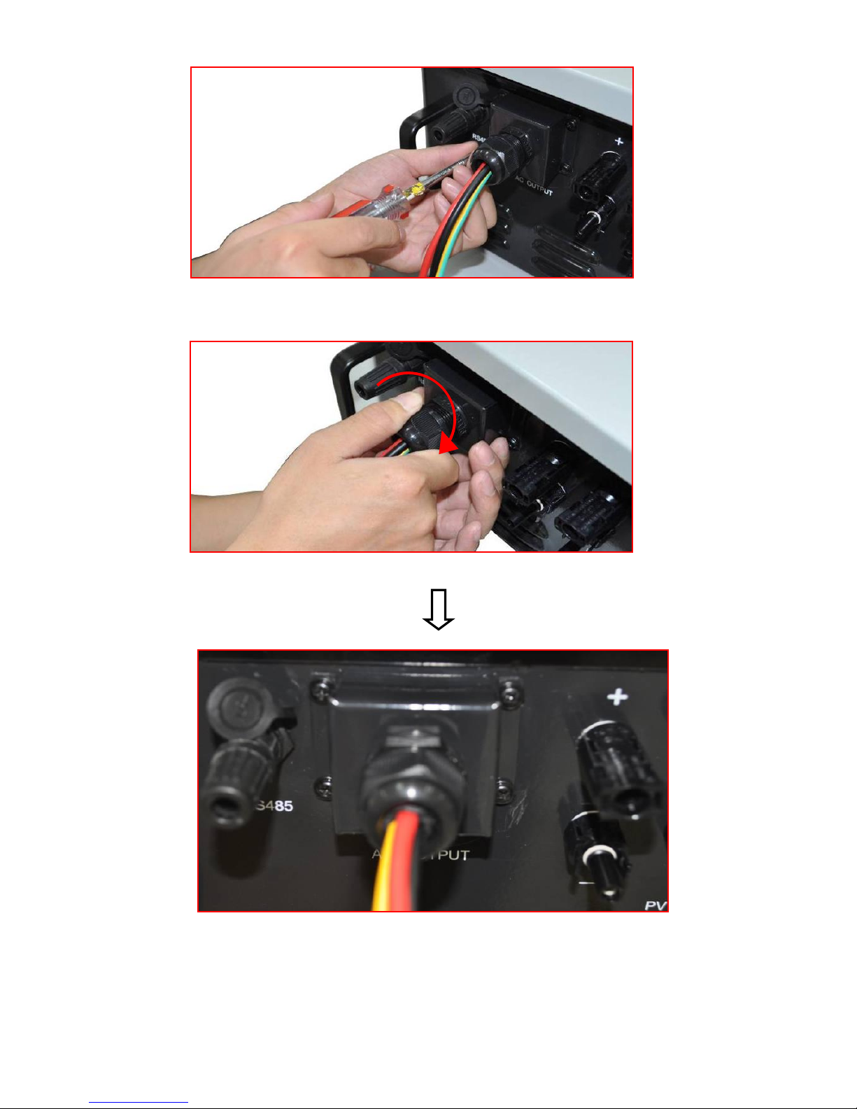
<<15
Step 4: Tighten the cable gland in clockwise direction.
Page 18
16>>
5.5.2 AC connection Procedure
Step 1: Assembling AC cables to connector supplied. See “5.5.1 AC Output Wring”.
Step 2: Make sure that AC and DC circuit breaker are disconnected.
Step 3: Connect L, N to AC circuit breaker.
− Plug AC connector to corresponding AC terminals.
− Screw AC cables to AC circuit breaker.
Step 4: Connect PE to the ground.
Step 5: Connect AC circuit breaker to utility grid.
Step 6: Make sure that all AC cables are firmly installed.
NOTICE
Assignment of AC cables should be paid attention to, especially
“PE/GND” wire.
5.6 Connecting communication cable
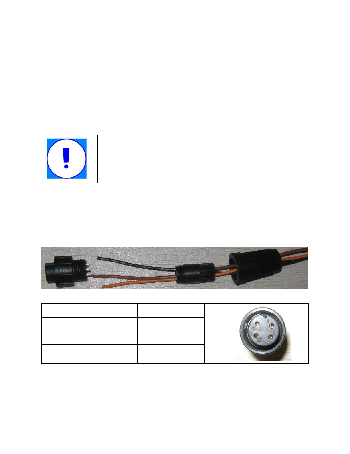
5.6.1 Assembling the RS485 plug connector
Step 1: Make the communication cable through the waterproof ring, and then
connect the cables to the terminal.
1
Blank 2
B
3
A
4
GND
2. Fasten the waterproof ring and case.
3. Finally, match the finished terminal to the RS485 communication port on the inverter’s
case,then it is ready for communication.
Page 19
<<17
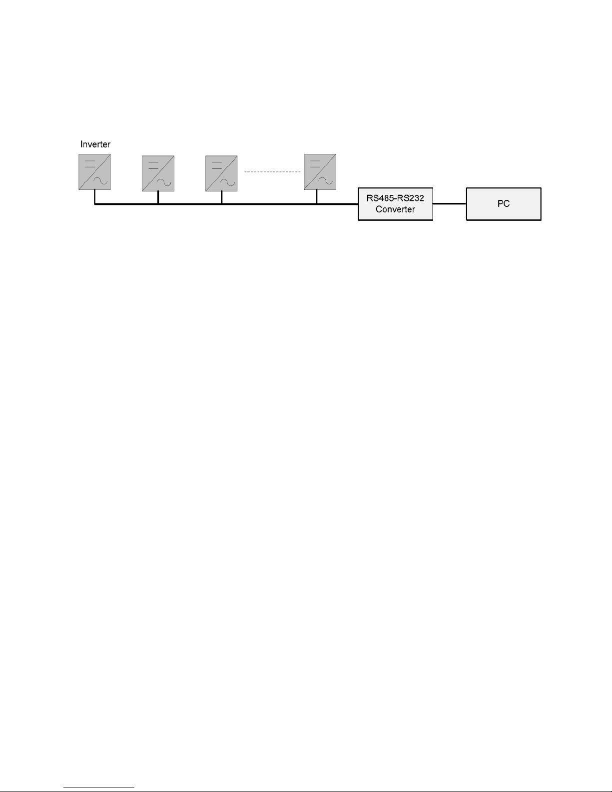
5.6.2 Monitor system connection
The inverter provides RS485 interface to communicate with remote PC. User can
monitor the state of the inverter and observe current running information and history
record via this interface. Below is the method to install the monitoring system.
6. Switch on and off
6.1 Switch on
1. Finish the installation of the PV array, AC grid and the inverter according to the
introduction before.
2. Before switch on, checking whether AC voltage and DC voltage can meet the
requirement of the inverter
3. Switch on the DC breaker at first.
4. Then switch on the AC breaker.
5. When the environment conditions allow the inverter to work, the inverter will
automatically start up and connect the grid to generate power.
6. After the inverter works normally on grid, it can be left working itself without human
control. It can shut down when fault occurs and it can start automatically after the fault is
gone.
6.2 Switch off
1. When solar power was not enough to generate the power, the inverter will shut down
automatically.
2. If you need to shut down the inverter yourself, you can operate the inverter through the
front panel screen.
3. The process of emergency shutdown.
If you need shut down the inverter in emergency, first turn off the AC breaker, then turn
Page 20
18>>
off the DC breaker, otherwise it may lead to the damage of the DC breaker and danger to
people. If any damage or loss occurs due to not following this requirement, we will not
follow the warranty.
7. Operation
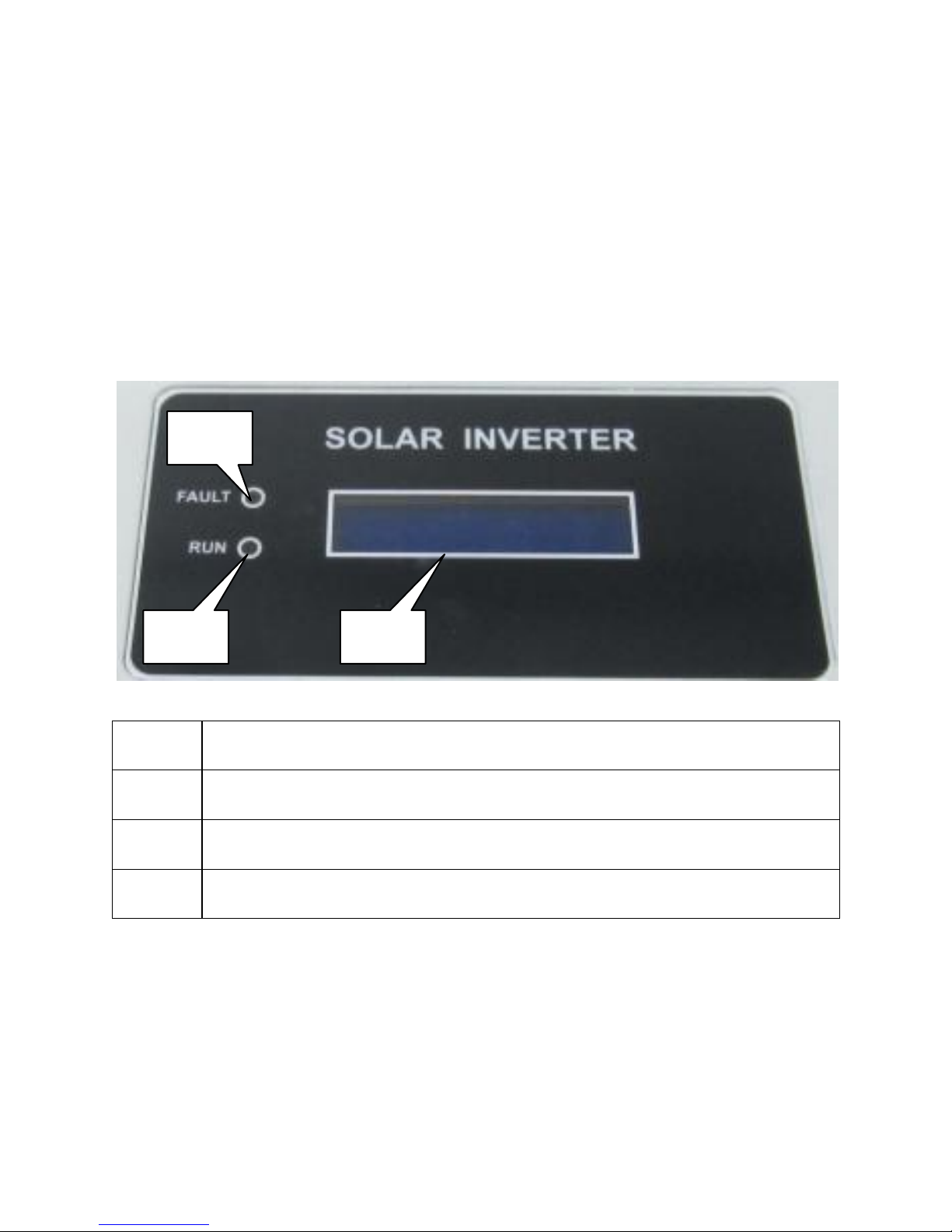
7.1 Display Overview
Object
Descriptions
A
GREEN LED (Working normally)
B
RED LED ( Fault)
C
2 line LCD display
7.2 LED display
The PV inverter is equipped with two LEDS including “green” and “red” which indicate
three different modes of operation.
Green LED: Normal mode
The green LED lighting indicates that the inverter is active and working normally.
B A C
Page 21
<<19
Whenever the supplied power from PV panel is sufficient (voltage>120VDC), Inverter
converts power to the grid. If the power is insufficient (voltage<90VDC), the inverter
enters a “waiting” state.
Red LED: Fault mode
The red LED indicates that the inverter has stopped feeding power into the grid because
of fault, and the corresponding fault information will display on the LCD at the same time.
All off: Shutdown mode
During peri
ods of little or no s
unlight, Inverter automatically stops running. In this mode,
Inverter does not take any power from the PV panels. The display and LED’s on the front
panel do not work.
7.3 LCD display
The LCD display consists of 16 characters and 2 lines. Once the PV power is sufficient,
the inverter starts up automatically. The inverter displays information as shown in the
flow chart as follow:
“Welcome” “Model: EPIG X K ” “Version
: x.xx” “ Waiting: xxS” “Normal State”
“Pac= xxx.x W”.
To save power, the LCD display’s backlight automatically turns o after feeding the grid 5
minutes. If there is a fault message appears, the LCD display’s backlight t urns on all the
time until the fault is solved.
Along with different working states of the inverter, the LCD display different information
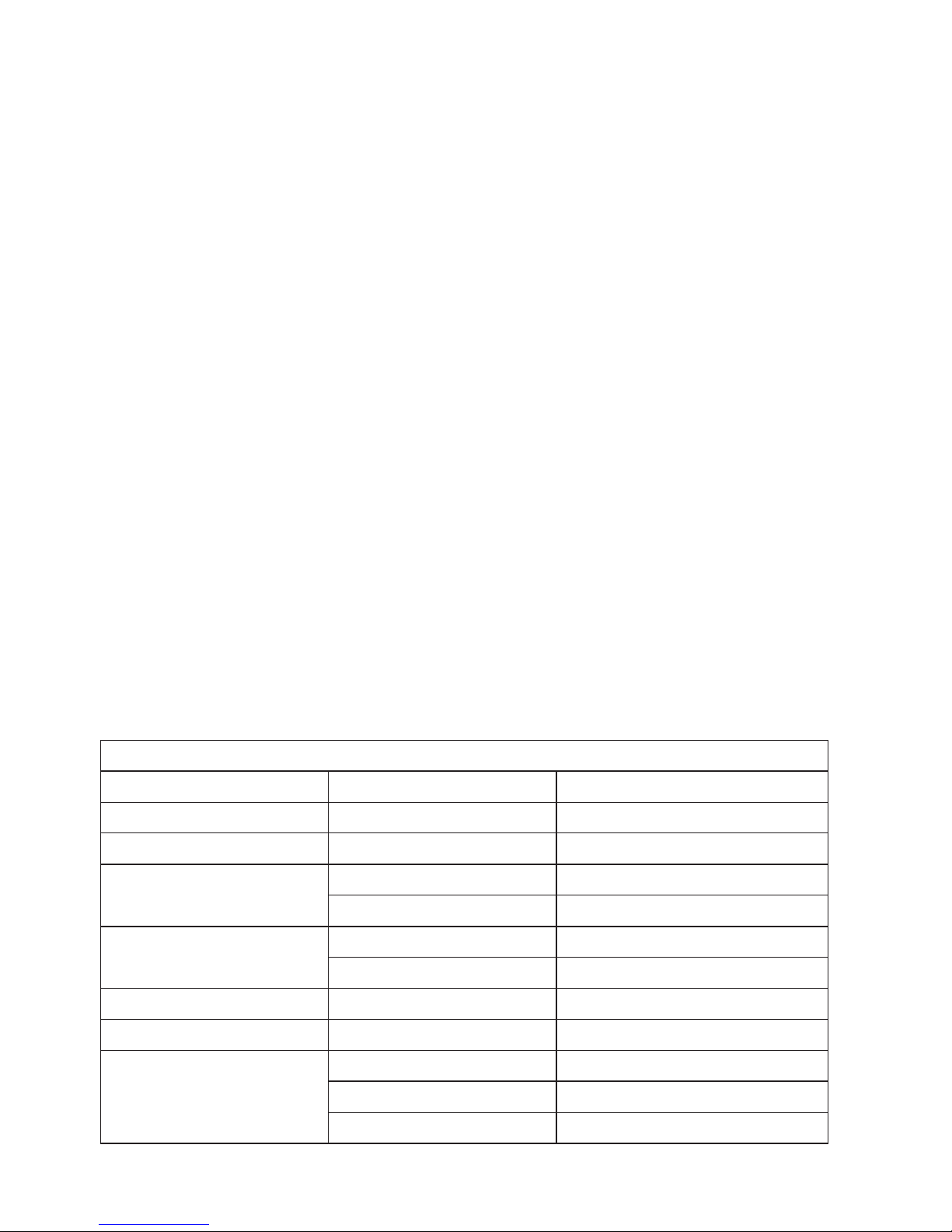
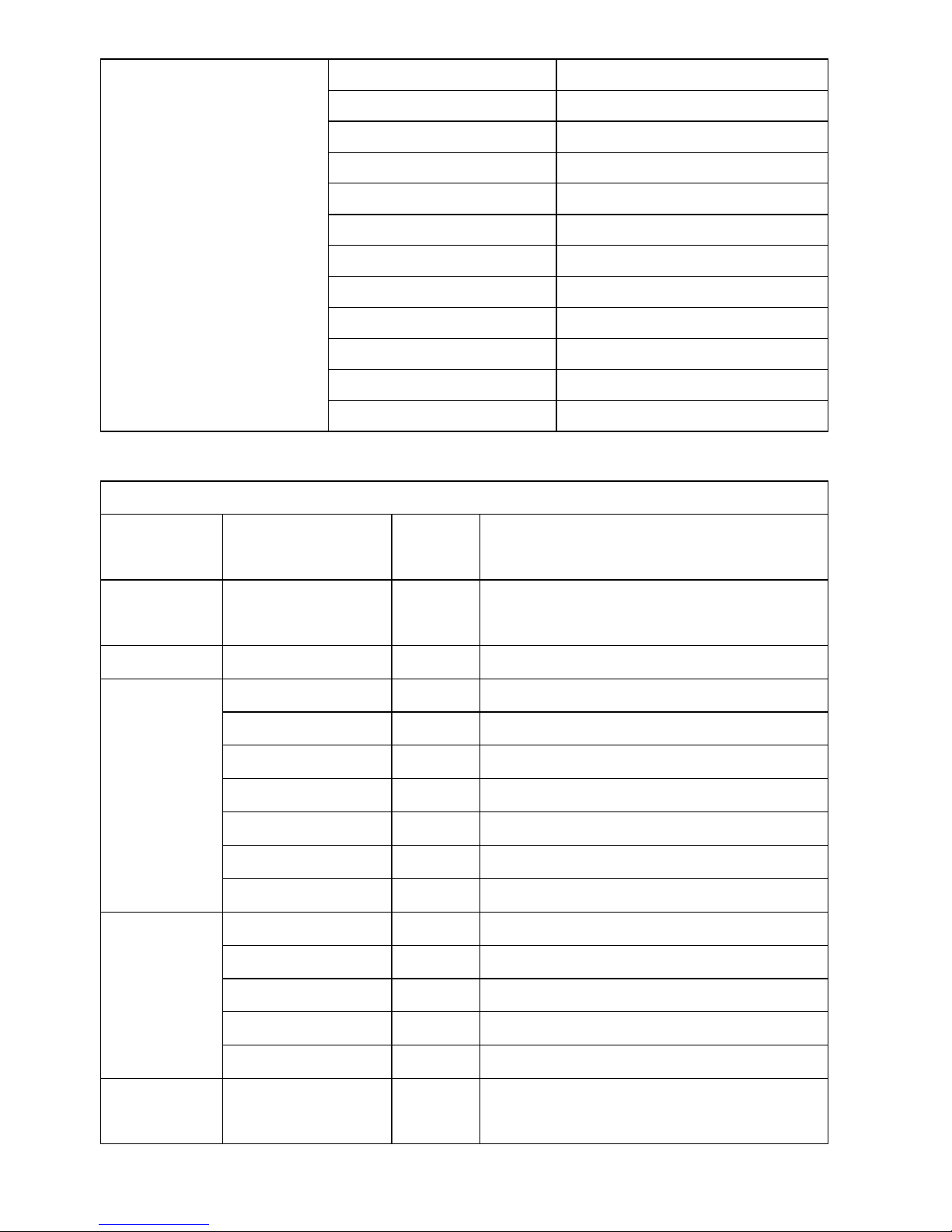
as follows:
The first line of LCD
System State
LCD Display Content
Remark
System Initial
Welcome
System initial default display
Standby
Waiting
waiting
Connecting
Connecting **s
System checking
Reconnecting **s
Again System checking
On Grid
Working
Inverter working
Pac= xxxx W
Inverter watt at working
Key stop
Shutdown
Key off
Waiting key start
Waiting Start
Waiting key start
Fault
PV Over Voltage
Dc over voltage
Island
Island or no grid
AC Over Voltage
Ac over voltage
Page 22
20>>
AC Under Voltage
Ac under voltage
AC Over Freq
Ac over frequency
AC Under Freq
Ac under frequency
High Temperature
Temperature abnormal
AD Channel Fault
Adc channel abnormal
High Iac Leakage
Ac leakage current over
Over Current
abnormal current
Insulation Fault
PV insulation fault
No Utility
No grid
High DC Component
Dc component over
Relay Check Fail
Relay check fail
Fault
fault clc
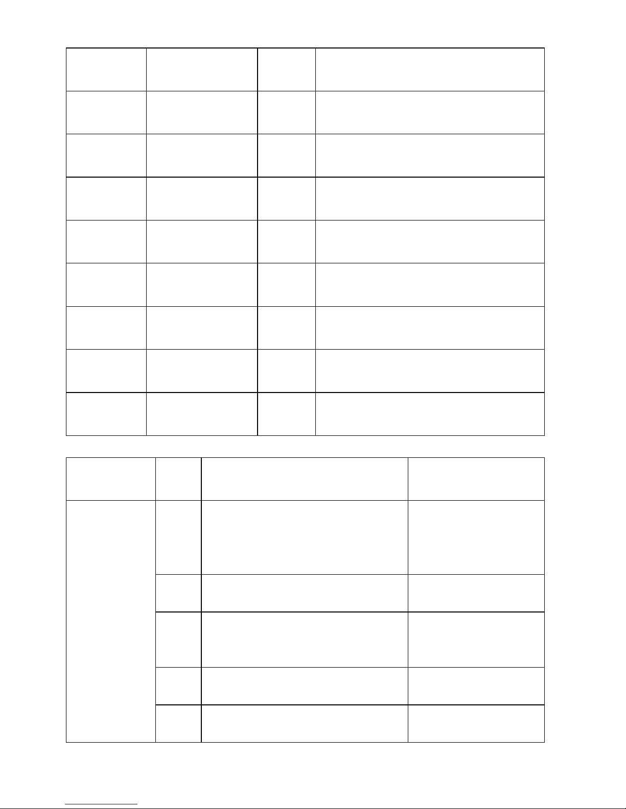
The second line of LCD
System
State
Cycle Display
Content
Display
Time /s
Remark
System
Initial
EAxK TUV x.xx
Machine model, grid standards,
software version
Standby
Null
2
Display null
Connecting
Company : XXXX
2
Manufacturer
Model: EAxKLPV
2
Inverter model
Version:x.xx
2
software version
PV:xxx.xV xx.xxA
2
PV voltage and current
BUS:xxx.xV
2
Bus voltage
AC:xxx.xV xx.xxA
2
Grid voltage and current
Freq:xx.xxHz
2
Grid frequency
On Grid
Etoday:xx.xxKWh
4
Energy today
PV:xxx.xV xx.xxA
4
PV voltage and current
BUS:xxx.xV
4
Bus voltage
AC:xxx.xV xx.xxA
4
Grid voltage and current
Freq:xx.xxHz
4
Grid frequency
Key stop
Null
Upper pc key stop, display until key
start
Page 23
<<21
Waiting key
start
Null
Upper pc key start, display until
entering standby
Fault
Info:xxx.xV xx
Dc over voltage fault value and fault
code
Info:xxx.xV xx
Ac over voltage fault value and fault
code
Info:xxx.xV xx
Ac under voltage fault value and fault
code
Info:xx.xxHz xx
Ac over frequency fault value and fault
code
Info:xx.xxHz xx
Ac under frequency fault value and fault
code
Info:xxx.xV xx
Relay check fail fault value and fault
code
Info:xxxx xx
Temperature abnormal value and fault
code
Waiting xxxs xx
Other fault display countdown and fault
code
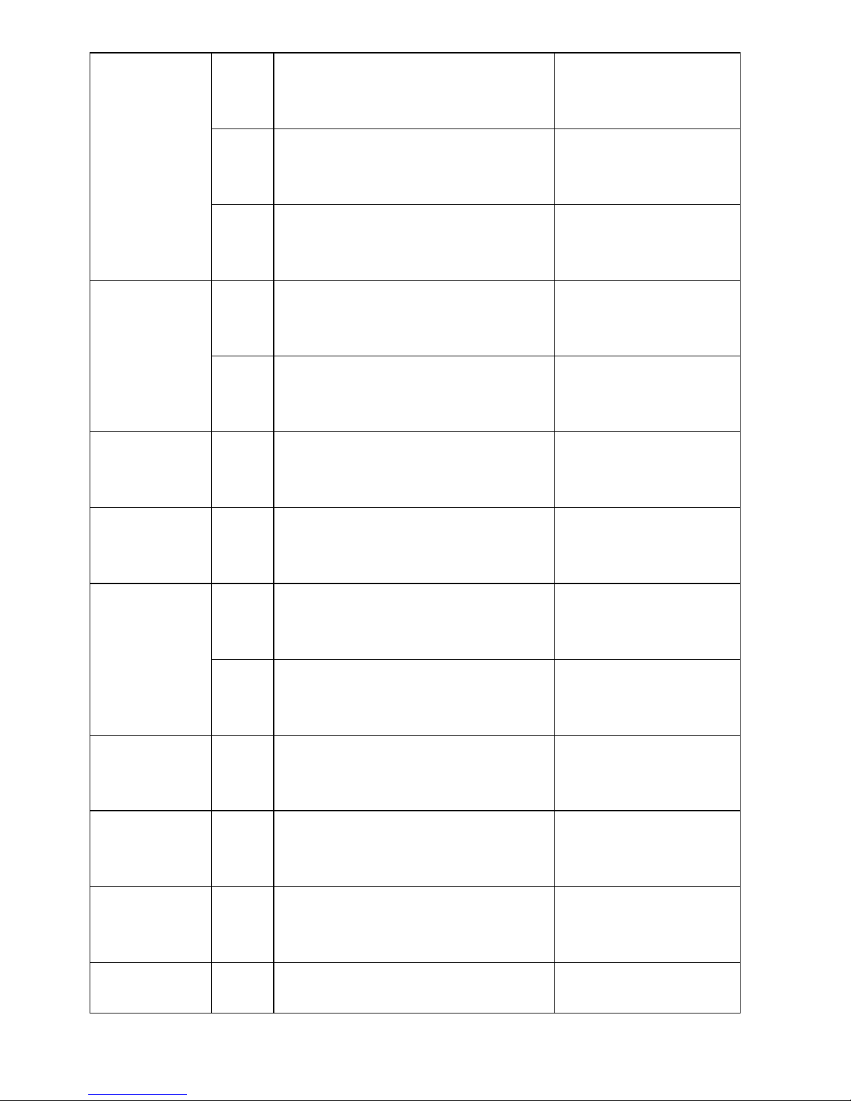
Fault
Messages
Fault
Code
Fault Descriptions
LCD displays
Island
1
The slave DSP detects the grid
fault, and communicates with the
master DSP through the parallel
port.
1.Island
2.NULL
2
System start checks grid fault
1.Island
2.NULL
3
Phase lock program detects zero
signal for three continuous grid
cycle
1.Island
2.NULL
4
Active islanding program detects
the grid fault
1.Island
2.NULL
5
Grid voltage is under 20V
1.Island
2.NULL
Page 24
22>>
Grid Over
voltage
6
Grid voltage is over 300V
1.AC over voltage
2.voltage value,fault
code
7
Grid voltage is over the preset over
voltage protection point
1.AC over voltage
2.voltage value,fault
code
8
While feeding grid, system detects
grid transient voltage over bus
voltage -15V.
1.AC over voltage
2.voltage value,fault
code
Grid under
voltage
9
Grid voltage is under the preset
under voltage protection point
1.AC under oltage
2.voltage value, fault
code
10
Grid voltage is under 110V and
over 20V,
1.AC under voltage
2.voltage value, fault
code
Grid over
frequency
11
Grid frequency is over the preset
over frequency protection point
1.AC Over Freq
2.Freque value, fault
code
Grid under
frequency
12
Grid frequency is under the preset
under frequency protection point
1.AC under Freq
2.Freque value, fault
code
Bus over
voltage
13
Bus transient voltage is over the
preset bus voltage protection point
1.Bus over voltage
2.Bus voltage value,
fault code
14
Bus voltage is over the preset bus
voltage protection point
1.Bus over voltage
2.Bus voltage value,
fault code
PV isolation
resistance
check
15
PV isolation resistance check fails
1.Isolation Fault
2.NULL
Output DC
Injection
check
16
While feeding grid, system detects
the dc current component injecting
to the grid.
1.High DC omponent
2.NULL
Temperature
check
17
Inverter inner ambient temperature
is too high
1.High temperature
2.Temperature value,
fault code
Leakage
current check
18
Ac leakage current is over the
preset protection value
1.High Iac Leakage
2.NULL
Page 25
<<23
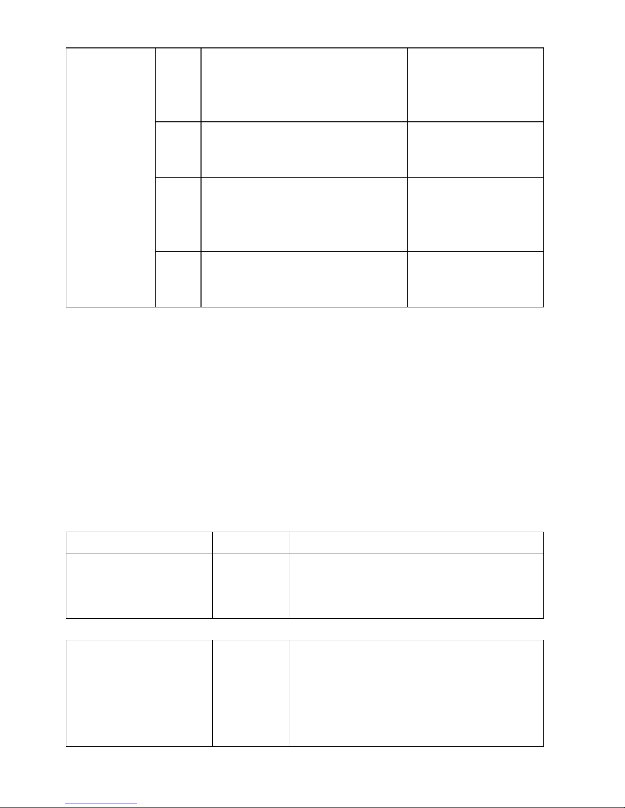
Relay check
19
Relay check phase 1 fails, when
the first group relays are closed
while the second group relays are
opened
1.Relay Check Fail
2.fault value and fault
code
20
Relay check phase 2 fails, when
the first group relays and the
second group relays are closed
1.Relay Check Fail
2.fault value and fault
code
21
Relay check phase 3 fails, when
the first group relays are opened
while the second group relays are
closed
1.Relay Check Fail
2.fault value and fault
code
22
Relay check phase 4 fails, when
the first group and the second
group relays are opened
1.Relay Check Fail
2.fault value and fault
code
8. Troubleshooting
8.1 Display Message
It is important to understand all operational and error messages that could appear on the
LCD display. The error messages that appear are especially important because service
personnel will need this information reported in order to help them to define the failure
and correct it.
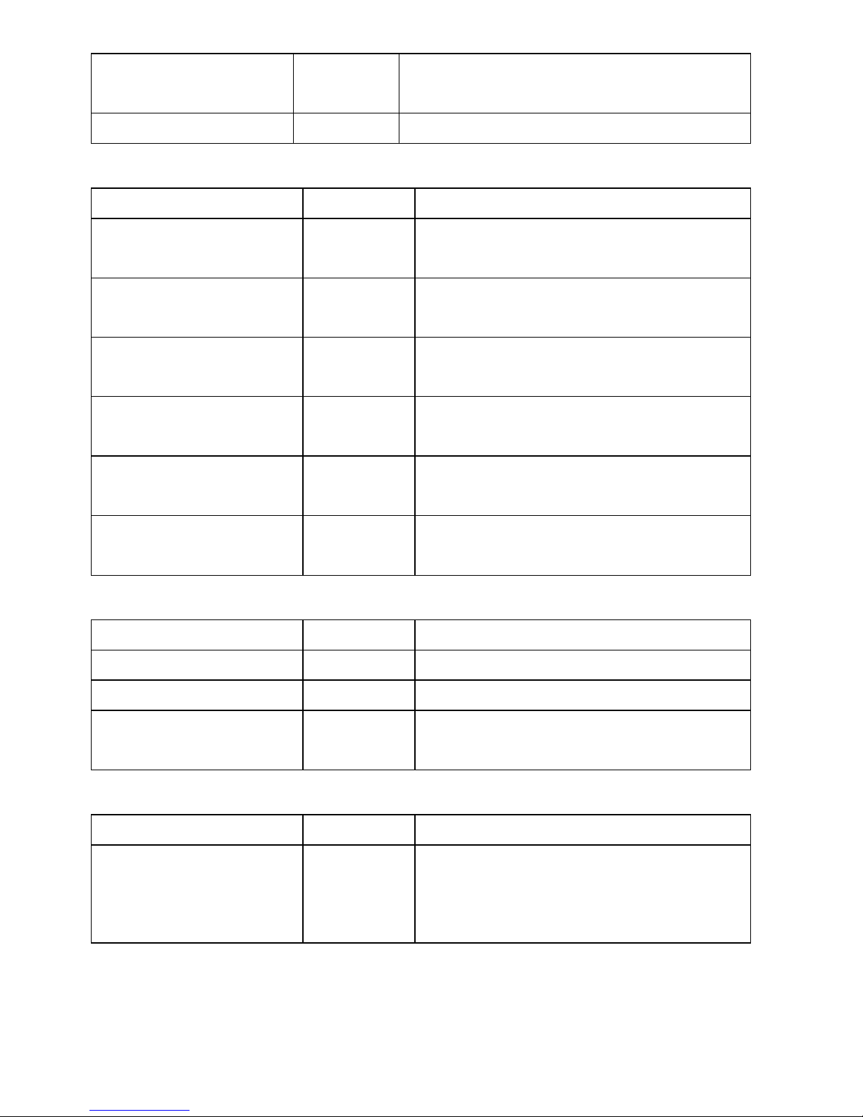
a. Working Status Messages
Operation Condition
Messages
Descriptions
Power Off
No Display
1.Initial condition: Before system startup
voltage (80V)
2.PV Inverter is totally shutdown, Vpv < 70V
Initialization and Waiting
Waiting
1.Initial condition: After PV voltage is higher
than 120V, inverter is waiting for feeding
to grid
2.After Startup: Input voltage range is at 80
~ 120V
Page 26
24>>
Check Grid
Connecting
xxxS
When PV voltage > 150V, inverter is
checking feeding conditions
Feeding Grid
Working
Inverter is feeding power to the grid
b. Monitoring Parameter Messages
Operation Condition
Messages
Descriptions
Instantaneous Output
Power
Pac=
xxxx.xW
The real time output power in xxxx.xW
Accumulated energy
information
Energy=
xxxxxxkWh
Total energy has been fed to the grid ince
inverter was installed
Today’s energy
information
Etoday=
xxx.xkWh
Total Energy that has been fed to the grid
today.
Grid Voltage and Current
AC:xxx.xV
xx.xxA
Grid Voltage in xxx.x VAC, feeding urrent
in xx.xxA
Grid Frequency
Freq:
xx.xxHz
Grid frequency in xx.xxHz
PV Array Voltage and
Current
PV:xxx.xV
xx.xxA
Input voltage and current from PV array,
c. System information Messages
Operation Condition
Messages
Descriptions
Model Display
EAxKLPV
Inverter Model
Software version
vx.xx
Software version
Waiting for reconnect to
the grid
Reconnect
in xxx S
The waiting time for reconnect to the grid
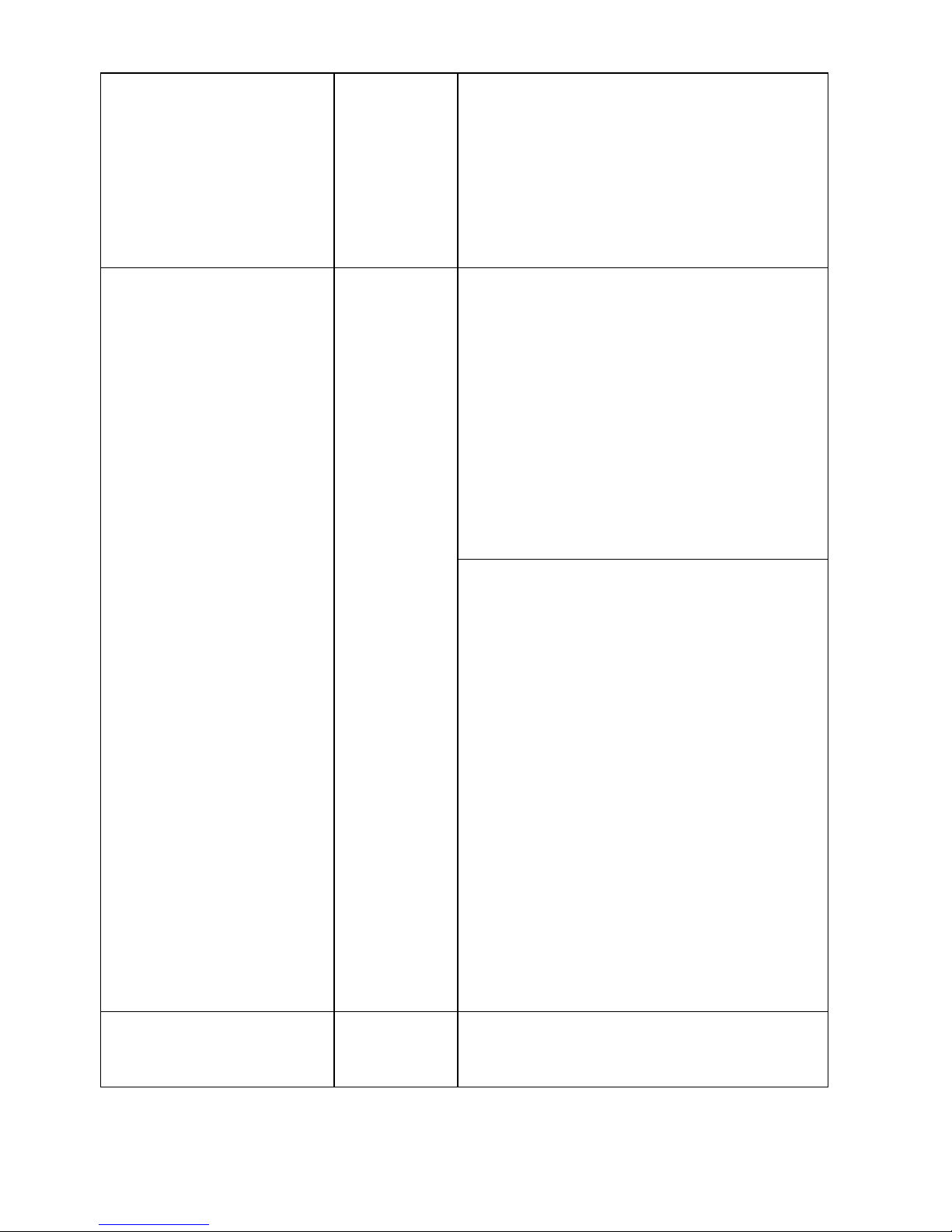
d. System Fault Messages
Operation Condition
Messages
Descriptions and corrective measure
Isolation Failure
Isolation
Fault
The resistance between the PV + or PV –
and grounding is outside the permissible
range, <500K.
Page 27
<<25
Corrective measures
◆Check the insulation of the PV plant
◆Check the PV plant for ground faults
and have the PV generator installation
engineer to fix the ground fault before
reconnect the string in question
Grid Voltage Fault
AC Over
voltage
AC Under
voltage
The grid voltage is not within the
permissible range. This fault can be
caused by any of the following conditions:
◆Power distribution grid disconnected
(miniature circuit-breaker, fuse)
◆The local grid condition is out of
acceptable range.
The inverter disconnects itself from the
public grid for safety reasons.
Corrective measures
◆Check the grid voltage and connection
on the inverter.
◆I If the detected grid voltage is within
permissible range, restart the PV Inverter
and try again. If fault remains, contact the
system installer to check the grid voltage
and cable connections between PV
Inverter and Utility system.
◆ If detected grid voltage is out of
permissible range, contact the system
installer to check the feed-in AC voltage
and contact the utility operator for further
action.
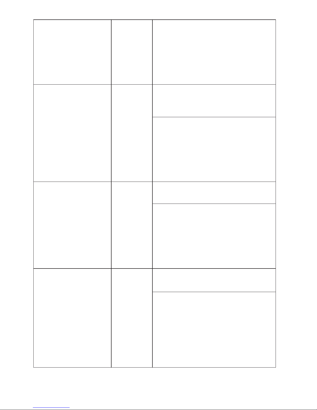
Grid Frequency Fault
AC Over
Freq
The grid frequency is out of the
permissible range.
Page 28
26>>
AC Under
Freq
Corrective measures
Check the grid connection and contact
the distribution grid operator if necessary.
If the power frequency is within the
tolerable range, but disturbances are still
displayed, contact the SYSCOM / EPCOM
Service line.
No Utility Island
Utility is not available. This can occur if the
AC fuse is broken, No AC connections
from utility system, or broken AC cables.
Corrective measures
Check the Utility system and the AC
connections of the PV Inverter
Check the AC fuses of the PV Inverter
If failure remains, disconnect the PV
Inverter and contact the system installer.
Input Voltage
too High
PV Over
voltage
Input voltage higher than 450V. The
inverter could be damaged.
Corrective measures
Disconnected PV modules immediately.
Check the configuration of the strings
for the PV modules in order to ensure the
maximum input voltage is lower than
450V.
Leakage current Fault
High Iac
Leakage
Leakage current on ground conductor is
too high
Corrective measures
Check the AC Cables Connections,
especially the grounding cables. Ensure
all the cables are connected properly.
Restart the PV Inverter.
If fault remains, disconnect the PV
Inverter and contact the system installer.
Page 29
<<27
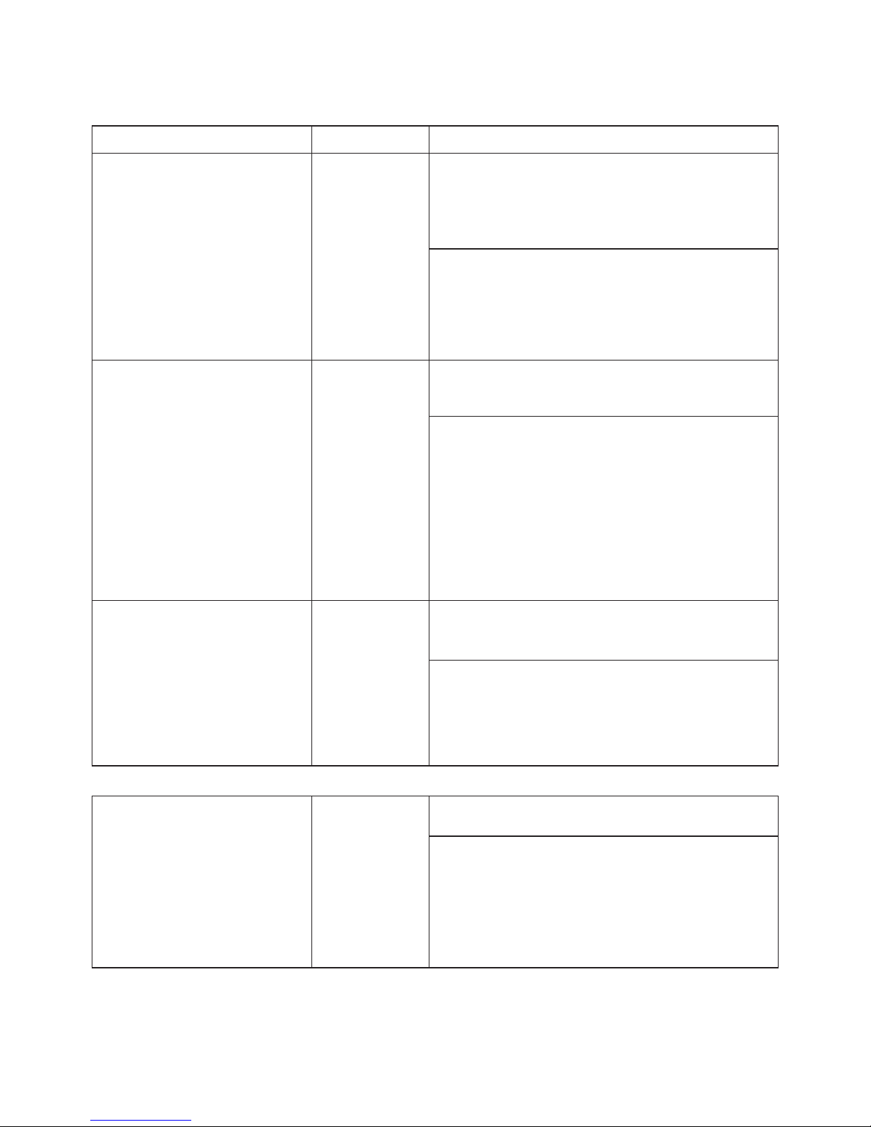
e. Inverter Fault Messages
Operation Condition
Messages
Descriptions
Consistent Fault
Consistent
Fault
The readings of 2 microprocessors are not
Consistent. It could be caused by CPU
and/or other circuit not functioning properly.
Corrective measures
Restart the PV Inverter.
If fault remains, disconnect the PV
Inverter and contact the SYSCOM
/ EPCOM Serv
ice line
Temperature too high
High
Temperature
The internal temperature is higher than
normally allowed value
Corrective measures
Disconnect PV Inverter for a period (>30
minutes) and then restart the PV Inverter.
If fault remains, disconnect the PV
Inverter and contact the system installer.
Select a new location for the installation
when if it is necessary.
Output Relay Failure
Relay check
fail
The relay between the inverter and grid is
not functional
Corrective measures
Restart the PV Inverter.
If fault remains, disconnect the PV
Inverter and contact the SYSCOM /
EPCOM service line
.
Output DC Injection too
high
High DC
Component
Output DC injection too high
Corrective measures
Check the connection of the DC Input.
Restart the PV Inverter.
If fault remains, disconnect the PV
Inverter and contact the
SYSCOM /
EPCOM Service line.
Page 30
28>>
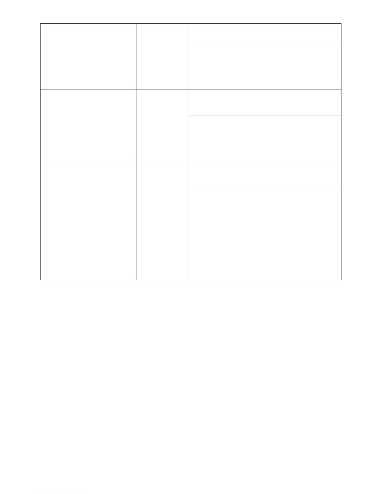
EEPROM Problem
EEPROM
failure
EEPROM inside has data access problem
Corrective measures
Restart the PV Inverter.
If fault remains, disconnect the PV
Inverter and contact the SYSCOM /
EPCOM Service line.
Communication failure
between microprocessors
SCI failure
Communication between MCU inside is
abnormal
Corrective measures
Restart the PV Inverter.
If fault remains, disconnect the PV
DC bus voltage is
too high
Bus Over
voltage
The DC BUS inside is higher than expected
Corrective measures
Check the DC voltage, if the DC voltage
is above the maximum input voltage,
contact the system installer.
If the DC voltage is under the maximum
input voltage, restart the PV Inverter.
If fault remains, disconnect the PV
Inverter and contact the SYSCOM /
EPCOM Service line.
Inverter and contact the SYSCOM /
EPCOM Service line.
Page 31
<<29
9. Technical data
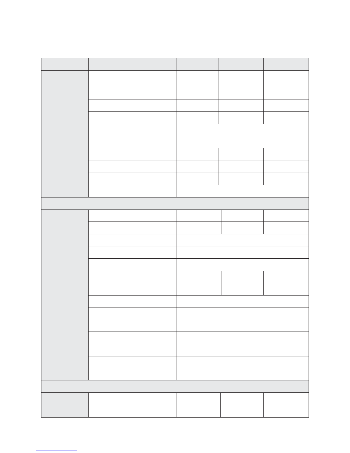
Specification/Type EPIG1K
Input(DC)
Max. DC Power 1200W 2300W
Max. DC voltage 450V 550V
MPP voltage range 90V-405V 150V-450V
DC nominal voltage 360 400
start voltage 150V
Shutdown Voltage Typical 80V
Max. input current 13.5A 15.5A
Number of MPP-Trackers 1 1
Number of strings 1 1
DC switch optional
Output(AC)
Rated AC power 1000W 2000W
Max. AC power 1100W 2200W
Nominal AC voltage 230Vac
Grid voltage range 180 V … 265 V
Grid frequency range 44 Hz … 55 Hz
Nominal AC current 4.4A 8.7A
Max. AC current 5.6A 11A
Power factor 1
Harmonic distortion (THD)
at rated output
<3%
Number of grid phases 1
Night consumption 0W
Power consumption at
standby
<6W
Efficiency
Max efficiency 96% 97%
Euro efficiency 94% 96%
EPIG2K
Page 32
30>>
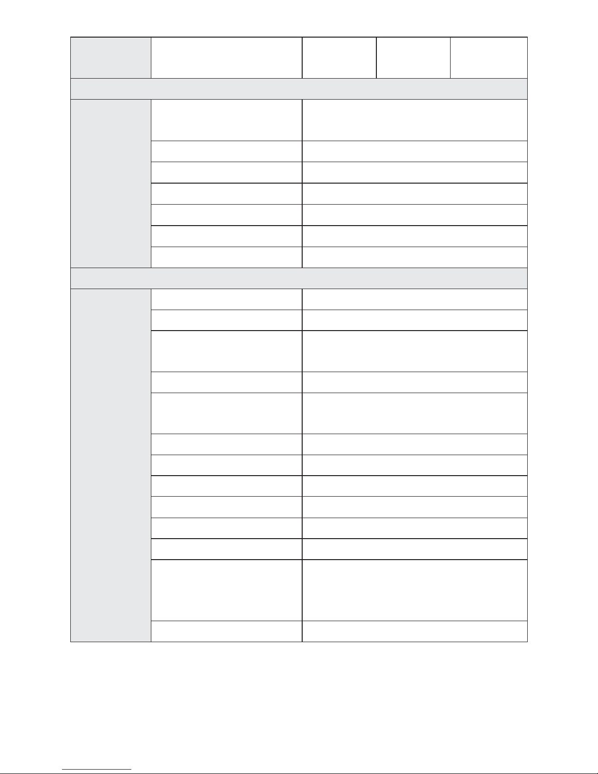
MPPT adaptation
efficiency
99.5% 99.5%
Protection
devices
DC reverse-polarity
protection
Yes
DC Insulation monitoring Yes
AC short circuit protection Yes
Grid monitoring Yes
Ground fault monitoring Yes
DC current monitoring Yes
Islanding protection Active Frequency Disturbance
General
data
Dimensions(W×H×D) 330mm×425mm×142mm
Net Weight 13.5kg
Operating temperature
range
–25 °C to +60 °C(up 45°C derating)
Relative humidity 0% to 100%, non-condensing
Site altitude
Up to 2000m without derating above sea
level
IP protection type IP65
Topology transformerless
Cooling concept Convection
Noise emission
<
40db(A)
LED display 3
LCD display Backlight, 16×2 Character LCD
Data logger
Data communication
interfaces
RS485
Warranty 5 years
Page 33

<<31
10. Appendix
10.1 Exclusion of liability
The content of these documents is periodically checked and revised, when
necessary, please call us for the latest information. However discrepancies cannot be
excluded. No guarantee is made for the completeness of these documents. Please
contact our company or distributors to get the latest version.
Guarantee or liability claims for damages of any kind are excluded if they are caused
by one or more of the following:
Improper or inappropriate use or install of the product
Installing or operating the product in an unintended environment
Installing or operating the product when ignoring relevant safety regulations in the
deployment location
Ignoring safety warnings and instructions contained in all documents relevant to the
product
Installing or operating the product under incorrect safety or protection conditions
Altering the product or supplied software without authority
The product malfunctions due to operating attached or neighboring devices beyond
allowed limit values.
In case of unforeseen calamity or force majeure.
 Loading...