

EPAK-TV TV44, TV59 User Manual
MANUAL / HANDBUCH / MANUALE
BASIC LINE
TV44 & TV59

The technical data, information and illustrations contained in this publication were to the best of
our knowledge correct at the time of printing. No liability can be accepted for any inaccuracies
or omissions in the publication, although every care has been taken to make it as complete and
accurate as possible.
The context is written in 4 languages: English, German, Italian and Spanish.
3 English
35 Deutsch
67 Español
101 Italiano
MANUAL
Basic Line
TV44 & TV59
English

4 English
English 5
Contents
1 The digital satellite tracking system ....................................................................6
1.1 EPAK®-TV system overview ............................................................................ 7
1.2 Safety recommendations ...................................................................................8
2 Installation .............................................................................................................9
2.1 Standard delivery .............................................................................................9
2. 2 Installation overview ........................................................................................9
2. 3 Selecting location ........................................................................................... 10
2. 4 Mounting surface ...........................................................................................11
2. 5 Planning the cable paths .................................................................................11
2. 6 Power supply ..................................................................................................11
2.7 Drillings .........................................................................................................11
2. 8 Mounting the antenna unit .............................................................................13
2. 9 System cable connections ..............................................................................13
3 Control elements .................................................................................................14
3.1 Control unit .................................................................................................... 14
5. 3 Delete stored data ...........................................................................................21
5. 4 Selection of stored satellites ...........................................................................22
5. 4.1 Manual selection of satellites ...............................................................22
6 Miscellaneous ......................................................................................................24
6.1 Compass calibration .......................................................................................24
6. 2 Adjustment of the LNB type .......................................................................... 24
6. 3 Special functions via the standby mode ......................................................... 25
6. 4 Fastscan function (US only) ...........................................................................25
APPENDICES
A Maintenance ..........................................................................................................26
B Overview of menu structure .................................................................................27
C Troubleshooting ....................................................................................................28
5. 4. 2 Automatic selection of satellites ..........................................................23
3. 2 Preparing the receiver ....................................................................................14
3. 3 Power on /off /standby ...................................................................................15
3. 4 Password access to Setup menu .....................................................................15
3. 5 Adjusting the setup parameters ......................................................................15
4 TV operation .......................................................................................................17
4.1 Stop Tracking function in harbors .................................................................18
5 Satellites ...............................................................................................................19
5.1 Adding new satellites .....................................................................................19
5. 2 Update of satellite data base ..........................................................................21
D Replacement parts .................................................................................................30
E Optional parts ........................................................................................................30
F System overview ...................................................................................................31
General cable data .................................................................................................31
G Elevation angles ....................................................................................................32
H Technical specifications ........................................................................................ 34
System overview illustrations.....................................................................................133
6 English
English 7
1 The digital satellite tracking system
1.1 EPAK®-TV system overview
Models Single Multi Receivers Bands
The advanced technology in the satellite tracking system EPAK-TV makes it possible to have an
excellent television reception wherever you are. Due to an unlimited 360° high-speed tracking, a
non-stop access to your favorite channels is guaranteed even during your trip on a vessel in open
seas.
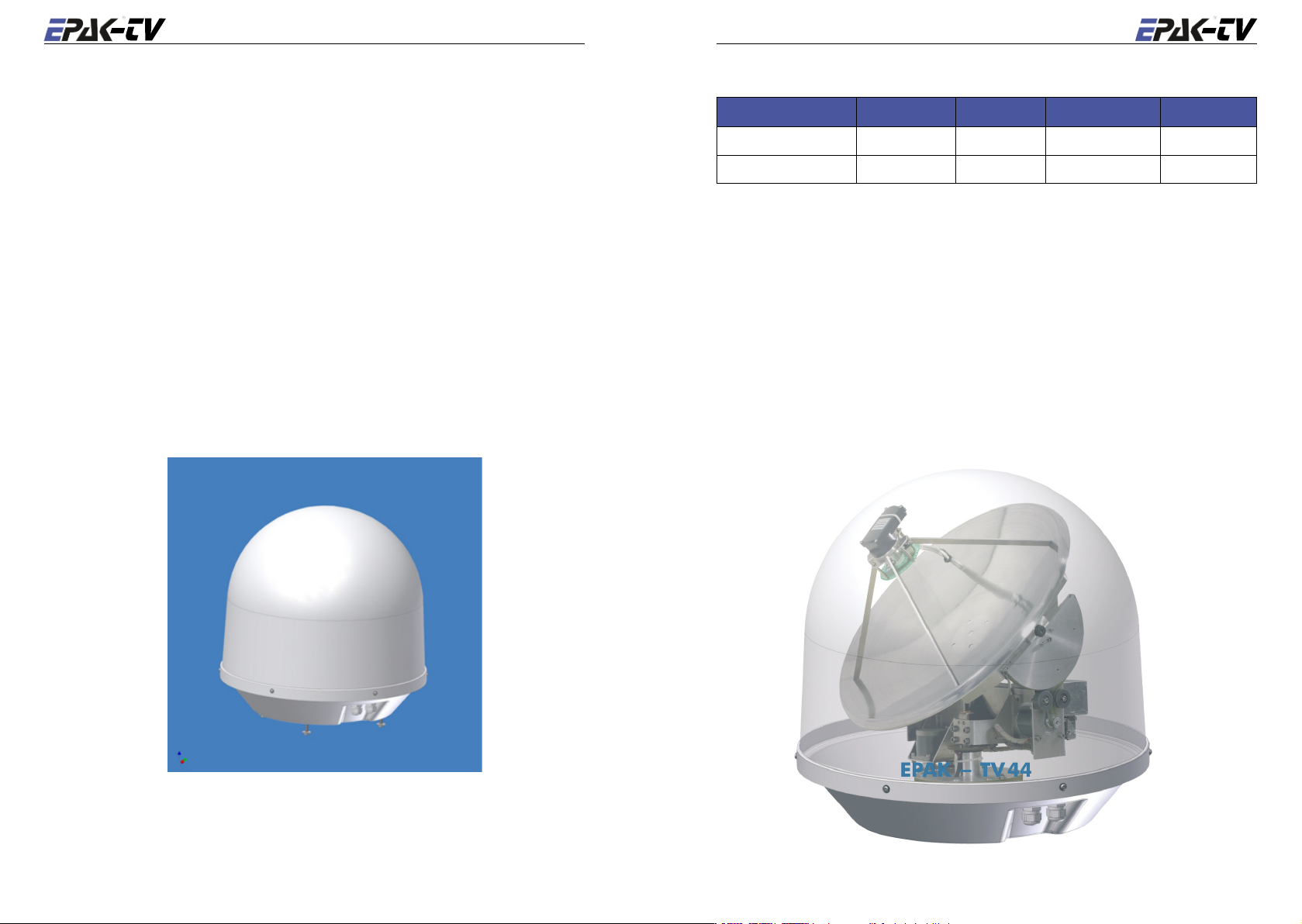
The satellite tracking system is protected by a UV-stabilized and maritime climate proof radome,
easy to handle and maintain. High-speed tracking sensors developed for this system, using hightech components of the electronic signal processing, provide the topmost and dynamic tracking
accuracy of the satellite tracking system. With the help of this technology, EPAK-TV guarantees
an unmatched tracking rate, dynamic and system performance. EPAK-TV is suitable for any size
vessel including smaller boats of less than 36 ft (11 m). The automatic satellite tracking system
includes a reflector antenna dish of 18" (45 cm) or 23.6" (60 cm) in diameter that is capable of
tracking horizontally and vertically by its direct servo drive (except TV45) to make an amazing
choice of channels available – just like home.
Once the connection to a satellite is established, the tracking system will stay connected to the
correct satellite even in the roughest sea conditions.
TV44 x 1 4
TV59
• On single antennas with more than one user (receiver), all the receivers will be on the same
band as the master i.e. if the master receiver switches band, all other connected receivers will
get this new band too.
x 1 4
Note! The reception of programs in different regions depends on the footprints of
the satellites. Also, the TV reception can be affected by rain, snow, dense clouds
and extreme movements in areas of weak signals.

8 English
English 9
1.2 Safety recommendations
2 Installation
➤ Please note that the maximum power voltage for the antenna unit must be between 12 and
36 volts DC, and the overload protection should be rated min. 5 amp. and max. 7.5 amp.
➤ When mounting the antenna, the distance from the antenna unit to other radiation sources e.g.
radar equipment or other antennas (mobile communication antennas) should be min. 2.5 m
(8 ft).
➤ Simultaneous operation of radar and satellite antenna may damage the satellite antenna if not
installed directly above the radar antenna.
➤
Do not use the control unit outdoors.
➤
During a thunderstorm, we recommend that the connection cables are disconnected.
➤ If the negative side of the antenna unit’s supply voltage has no connection to ship’s ground
(earth), then the antenna unit’s ground point should be connected directly to ship’s ground
(earth).
➤ After the installation is completed, all other electronic systems i.e. GPS, Radar, VHF, FM, AM
etc. should be tested for full functionality, while the antenna is turned on.
➤ Do not test or turn on the antenna before the radome is fitted correctly. If the sun reflects into
the dish, the electronics can be damaged.
Do not touch the rotary joint.
➤
➤ Do not attempt to open the sealed electronics, as this will void the warranty.
2.1 Standard delivery
The satellite tracking system EPAK-TV comes complete with electronic assemblies, cables and
other necessary installation material.
System components:
• Antenna unit (with serial number)
• Control unit
• Four mounting screws M 8
Please check the completeness of all components. Make sure that no transport damages exist be
fore you start the installation.
2. 2 Installation overview
The installation work has to be done in the following order:
• Select location
• Check the mounting surface for stability
• Check cable path
• Position of power distributor
• Drill holes and lay the cable
• Install antenna unit (see also addendum for instructions of how to undo the fixed
transportation position before power-up)
• Make all installation openings watertight
• Connect cables
For the installation the following tools are needed:
• Electric drill
• One 4mm and one 8.5-9 mm bits
• Hexagon socket wrench size 6
• Wrench M 8
-
☛ Plan the entire installation first! To avoid mistakes or damages to the boat or satellite track-
ing system, please read the installation instructions carefully before starting the installation.
10 English
English 11
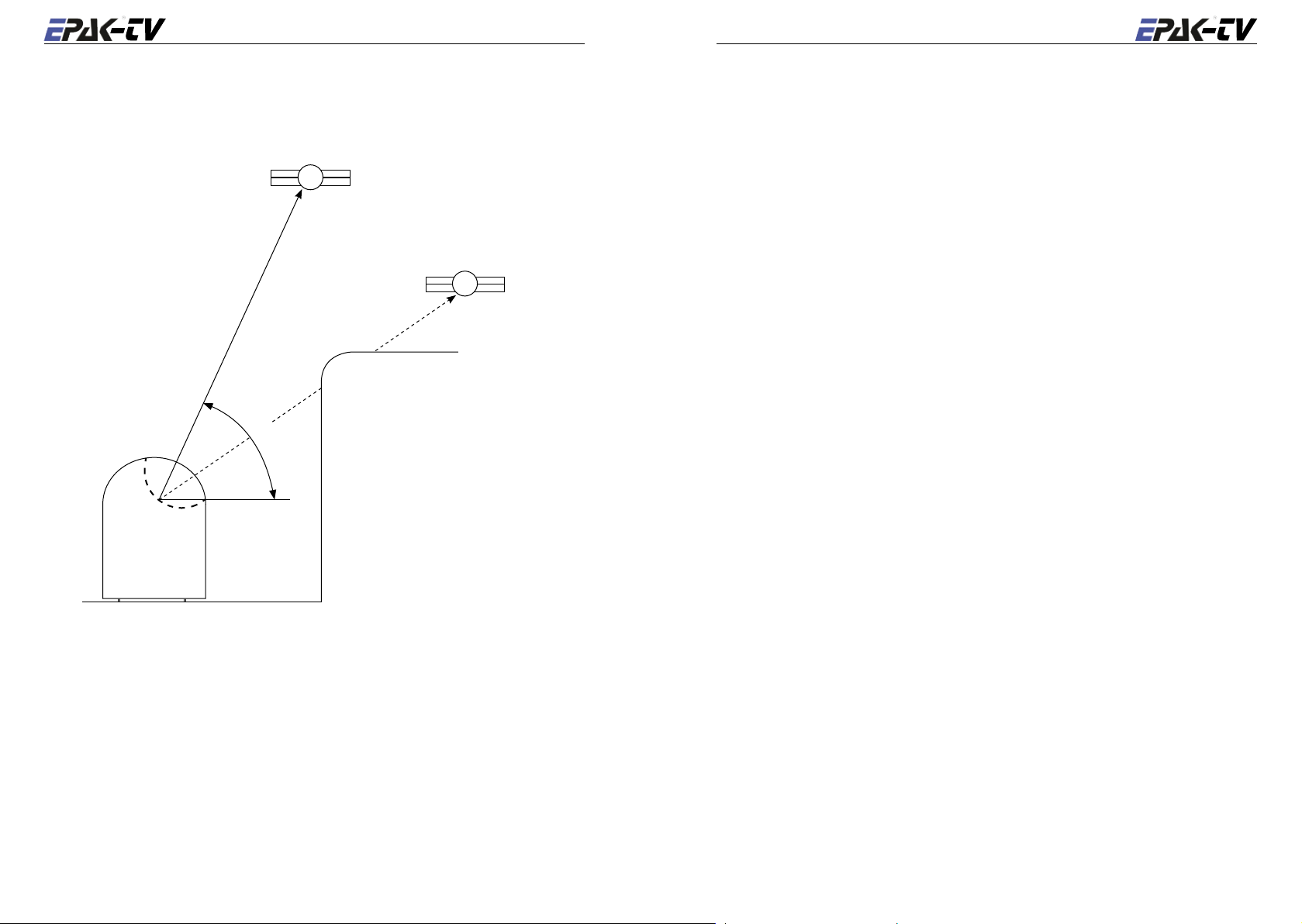
2. 3 Selecting location
2. 4 Mounting surface
This illustration shows the importance of a proper location for the antenna unit.
satellite
good view
satellite
bad view
e
l
antenna
e
v
a
t
i
o
n
a
n
g
l
e
boat
A horizontal, solid and steady surface is very important. Make sure that the surface does not have
any irregularities! Furthermore, please take into consideration that the weight of the antenna unit
is 40 lbs. (18 kg) or more. Therefore, the surface has to be strong enough to carry the antenna unit,
even during the most challenging maritime conditions.
2. 5 Planning the cable paths
Before starting the installation, you should check which walls are suitable and if existing openings
can be used for the cables.
☛ All openings have to be sealed in order to avoid any water penetrating.
The control unit should be placed as close as possible to the receiver. The maximum length of the
cable is 3 meters. Refer to Appendix F for data concerning appropriate cable types.
2. 6 Power supply
The antenna unit can be connected directly to any ship’s power supply net of 12/24/32 volts DC.
The circuit fuse should be rated for min. 5 amperes and max 7.5 amperes! (See appendix H “Tech
nical Specifications”).
☛ The power distributor must be idle while working on the ship’s supply net or you may short
circuit the system.
If the negative side of the supply voltage of the antenna unit has no connection to the boat ground,
make sure a potential compensation between boat ground and the ground point of the antenna
unit is made.
-
Note that criteria such as an unobstructed view to the satellite and a strong mounting surface are
met. Furthermore, no sources of interference, e.g. radar equipment or other antennas, such as
mobile communication antennas, should be installed nearby the Marine TV antenna unit. A mini
mum distance of 8-12 ft. (2-3 meters) has to be observed in order not to affect the picture quality.
Although the radome is sealed, it is recommended to avoid direct waves and bilge water!
The antenna unit has to be installed so that no superstructures will obstruct the sight to the satel
lite! Please note, that the elevation angle depends on the geographical location of the boat and on
the selected satellite!
☛ Equally important for a good installation are the conditions of the mounting surface and the
lengths of the different cables. See section2.4, 2.5 and 2.6.
2.7 Drillings
-
-
To avoid any damage to the mounting surface it is recommended that you start out with drilling a
smaller hole, using a 3.5-4 mm bit before drilling the correct hole size. Use an 8.5-9 mm bit to drill
4 mounting holes for the M8 screws included. To drill the holes in the correct positions, please
refer to the included template.
12 English
English 13
Example of template:
2. 8 Mounting the antenna unit
The antenna unit has to be mounted on a solid and steady surface. Take care that the cable lengths
228,6 (9")
134,2
127 (5")
are sufficient, the antenna unit must have an unobstructed view to the satellite and there must be
no interference fields (especially mobile communication antennas) nearby.
Place the antenna unit on the pre-drilled holes and fasten it with the included screws and washers.
The screws have to be screwed in from below through the mounting surface into the radome.
☛ Close all drillings with waterproof sealing material to avoid any water penetrating!
2. 9 System cable connections
☛ Break the contact of the circuit on which you are working to avoid short circuit the system.
77,5
127 (5")
228,6 (9")
• The antenna cable must be connected to the control unit and the antenna unit.
• The power supply cable to the power distributor and the antenna unit.
• The receiver cable to the control unit and the receiver.
See system overview and illustration details in Appendix F and at the end of the manual.
Lead the cable through the drilled holes and seal it with waterproof sealing material. Furthermore,
drip loops should precede the entry point from the exterior to avoid any water penetrating, see
below illustration:
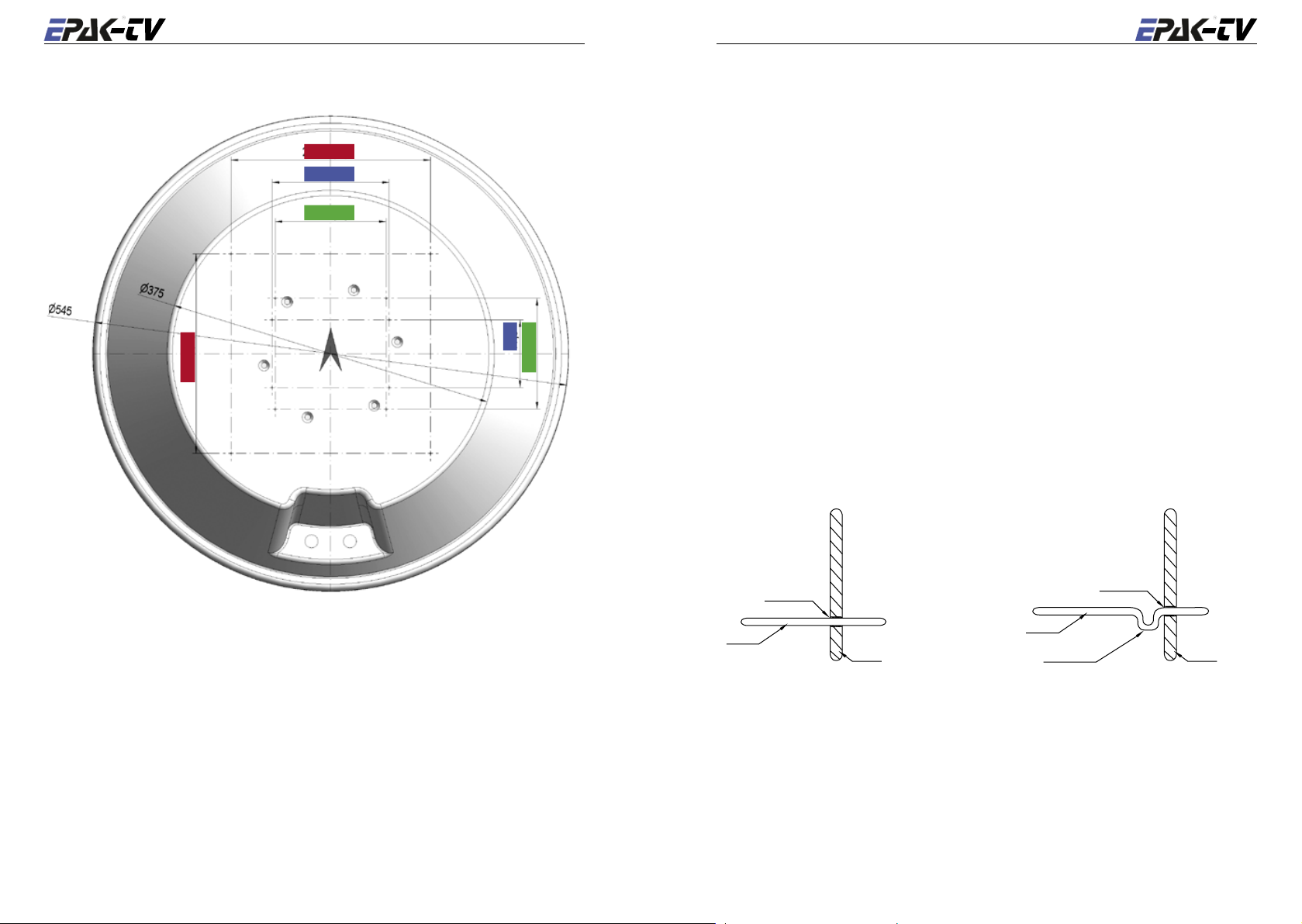
Bottom seen from below:
the drilling templates: 9" = KVH, 5" = Orbiscan, 134,2 mm x 77,5 mm = EPAK.
Before mounting, drill 4 holes ø = 8,4 mm into the bottom, refering to your preferred drilling
template.
Important: Please tell us with your order, what drilling template will be used and how thick is the
mounting ground, that the correct screws are delivered with the antenna.
☛ If the antenna unit is mounted on the cabin roof (not device carrier or separate mounting
plates) close all drillings with waterproof sealing material to avoid any water penetrating!
WRONG
sealing
cable
boat
Find a suitable location for all units within cable lengths. That means that the control unit should
be placed nearby the receiver. Take care that the display of the control unit can be easily read and
the push-buttons are accessible. And also, allow room for the cables behind the control unit!
The antenna unit is separated from the power supply net by the control unit. Therefore, the an
tenna unit has electric power when the control unit is turned on!
CORRECT
cable
drip loop
sealing
boat
-
14 English
English 15
3 Control elements
3. 3 Power on /off /standby
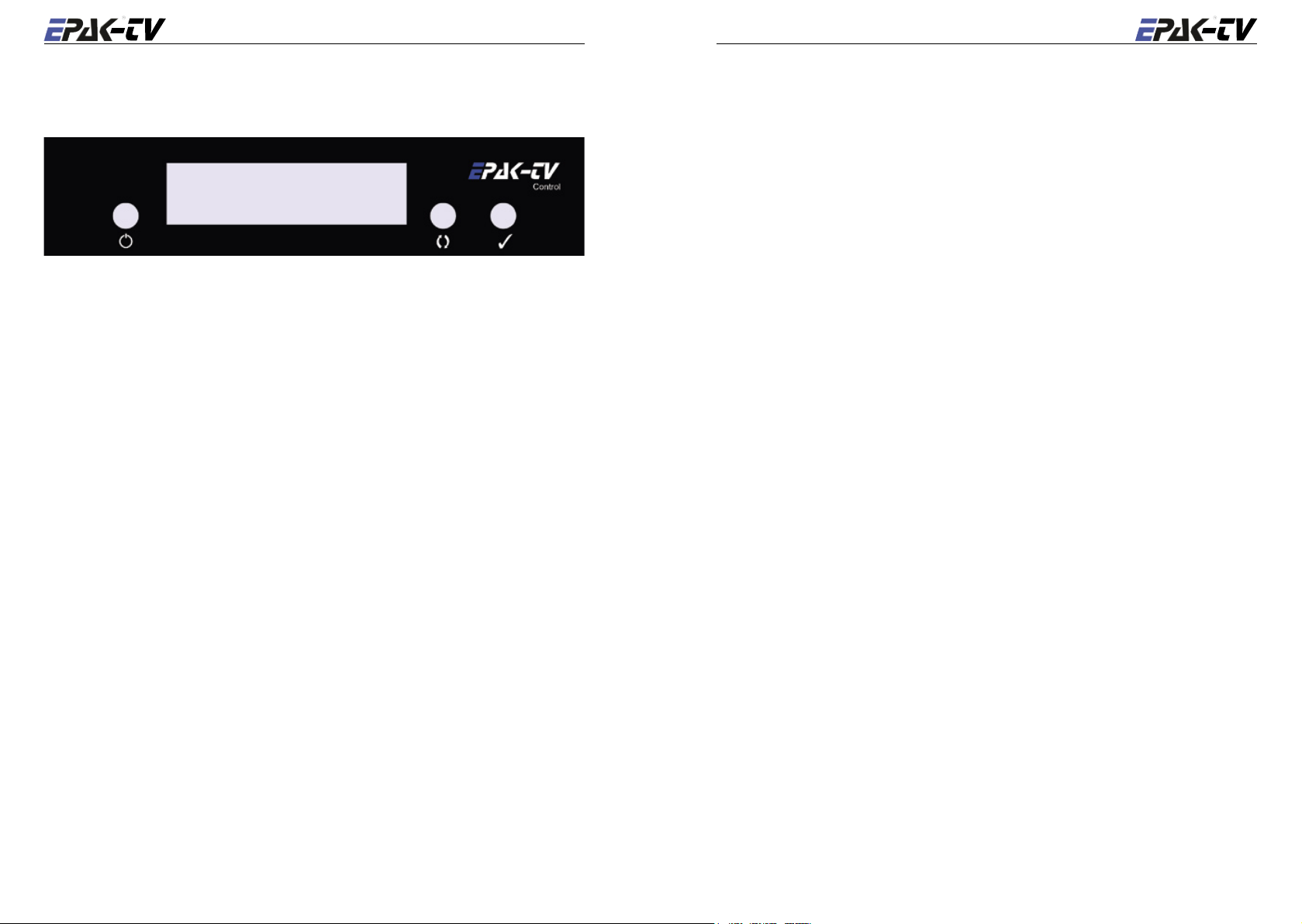
3.1 Control unit
The operation of the EPAK-TV system is controlled from the control unit. It is a good idea if you
make yourself familiar with the key functions and to memorize their usage in the menu struc
ture:
Power key: Short press will turn on the power or will enter Standby mode after initialization.
Browse key: Short press will browse through all available menus, step by step.
Select key: Short press will select/confirm what is written in the display.
Note! From the Standby mode: Hold Select key depressed while using the Browse
key to scroll through available data: serial no., counteroperation time, and soft
ware versions. See section 6.3.
3. 2 Preparing the receiver
EPAK-TV does not need a special receiver. The satellite tracking system can be connected to any
commercial receiver for digital and analogue reception. Only the LNB-type in the setup menu of
the receiver has to be set on “Universal” (LOF 9,75/10,6 Ghz). If you want several satellite posi
tions, the DiSEqC ™ function for an automatic satellite switch has to be activated.
To program your receiver, please refer to the respective owner’s manual!
☛ For every satellite at least one program must be preprogrammed in the receiver to control the
satellite position of the antenna unit by means of the TV picture quality. If not, preprogram
the receiver by using an already installed satellite system!
☛ In case the receiver supports the function, adjust the receiver so that the power supply of the
LNB is turned off during the standby-mode. This means that the control unit and the antenna
unit are without power supply. This function enables the turning on and off of the antenna unit
via remote control of the receiver, which lowers the power consumption.
☛ In case several receivers are connected to the antenna simultaneously (e.g. a digital receiver
with analogue receiver looped through) both receivers must have identical DiSEqC ™ set
tings i.e. active or inactive.
The antenna unit is controlled by the control unit, which is turned on by pressing the (power)
key. To enter Standby mode, press the
key from any menu after the initialization is completed.
☛ When the control unit is in standby mode there will be no power supply to the antenna.
3. 4 Password access to Setup menu
To gain access to the setup menu will require that you first enter a password. It is always the same
-
-
password which have to be entered. When
1. Press The display will show: ----
2. Press The display will show: X---
3. Press The display will show: XX--
4. Press The display will show: XXX-
5. Press The display will show: XXXX
The time between each keystrokes should not exceed two seconds or the password request will
be annulled. If so, the display will return to a flashing
point 1. If the password is entered correctly, you are now in the Setup menu.
Setup
is flashing in the display:
Setup
and you will have to restart from
3. 5 Adjusting the setup parameters
Modifications can only be made in the setup menu. In the main menu only the flashing functions
can be selected.
Init
-
-
1. Turn on the control unit. The display shows
progress.
2. After the initialization is completed, you are in the main menu with the display flashing
Setup
3. If the password is entered correctly, you are now in the setup menu. The display shows
Tracking
4. Tracking is preset to On. Toggle between On and Off with the
deactivated (see section 4.1). With On, tracking is activated i.e. the satellite can be tracked.
Press to select.
5. The display shows
or to continue from point 7.
6.
Fastscan
6.4). With On, Fastscan is activated i.e. the search for the correct satellite works faster (US
only). Press to select.
. The setup menu has password access − see section 3.4.
, press to select.
Tracking
is preset to On. Toggle between On and
. Press to go to
(flashing), meaning initialization is in
key. With Off, tracking is
FastScan
Off
mode. Press to select
with the key (see section

16 English
English 17
7. The display shows
8. The display will show the standard setting
key you can change the LNB settings. Press to select. The display will return to:
Type
.
☛ The standard setting
satellites with a rotated skew will require an optional LNB mounting with variable skew (see
Appendix E). Reception from circular polarized satellites will require a circular LNB type.
9. Press
repeatedly until the legend
FastScan
lin 0
is the only one supported by a standard system. Reception from
. Press to go to
lin 0
Comp Cal
which is valid for Europe. By pressing the
appears. Press to select.
LNB Type
. Press to select.
LNB
☛ The calibration of the compass must be carried out in the harbor in calm waters! If the mount-
ing surface of the antenna unit changes, or if the superstructures in the vicinity of the antenna
unit are modified, the calibration has to be done again! See also section 6.1.
10. The display interchanges between the legends:
calibrate.
11. The display interchanges between the legends:
checking
Comp Cal
12. Press
The system is now adjusted to surrounding conditions and is ready to search for satellites to be
stored.
until the legend
, which indicates that the calibration of the compass is completed.
to go to
quit
complete
, and press to confirm.
Compass
Compass
is shown for a brief moment, and then returns to
and
UpDate?
and
. Press to
calibrat
and then
4 TV operation
Press the power key to turn on the control unit. The display shows
the initialization is completed, the display interchanges between
is the last shown storage position) until the satellite has been located. The system will now run a
check on the satellite:
then return to
The antenna will maintain its connection to the satellite even when the boat is moving. (Providing
that the tracking function is active, see section 3.5).
If you wish to select a different satellite, press
appears, and then confirm with
Sat
☛ If no satellites are stored, the display will show
main menu and can add new satellites (see sec. 5.1).
If the search for a new satellite takes more than 1 minute, even though there is a clear view to the
satellite, or if, after several times finding the right satellite, the display shows
interchanging with the actual satellite number, then the satellite data base has to be updated, see
section 5.2.
If there is no picture on the TV after the satellite has been checked and found o.k., there are two
possibilities:
1. The satellite service provider has changed the transponders or it is the wrong satellite. In order
to proof the right satellite has been found, try to switch to other programs on the receiver. If all
other programs are in their usual places, you need to reprogram your receiver for the program
which have changed. Please refer to the manual of the receiver.
2. US only: In case that no program can be received, try to turn off the Fastscan function, see
section 6.4.
When changes are made, return to
If the search for a new satellite takes longer than 4 minutes and after some time the display shows
Sat ok?
sented and the operator can choose one.
Make sure the receiver is switched to a program from this satellite, so the correct satellite can
be identified. If the display shows
continue the search.This has to be repeated, until the TV shows the correct program. Press
confirm.
The display will now interchange between
ellite data base. The display will flash:
complete
the TV. If the display interchanges between
no suitable satellite could be found. Press
Setup
, then the requested satellite could not be found. All available satellites will be pre-
. The display will now return to
.
checking
X.
. If o.k., the display will briefly indicate
repeatedly until the desired satellite position
.
Setup
Sat
X and press to start a new search.
Sat ok?
updating
and there is no picture on the TV, press to
Sat
X and
UpDate?
, and shortly after:
Sat
X and the requested program will appear on
scanning
and
to go to the main menu and the display will flash
Init
for initialization. After
scanning
(flashing). You are now back in the
and
Sat
X (X
complete
upd reco
and
and
to
. Press to update the sat-
checking
complete
, and then:
during the search,
18 English
English 19
Check all cable connections and make sure there is a clear view (no obstacles) to the satellite and
the receiver is correctly adjusted. Then repeat this procedure.
5 Satellites
☛ The menu item
tion 4.1).
Should the antenna lose the signal from the satellite (due to a passing boat, buildings on shore,
bridges, or superstructures on own boat), the display will interchange between
sition of current satellite) and
The tracking mode will automatically restart when the vessel is turned. The display interchanges
between
the vessel or the satellite cannot be found!
☛ If you wish to select a specific satellite, refer to section 5.4.
scanning
Upd Sat
no Sig
and
Sat
is not shown when the tracking function is deactivated (see sec-
Sat
X (stored po-
, for the duration of the missing satellite reception.
X. In case superstructures obstruct the view to the satellite, turn
4.1 Stop Tracking function in harbors
If the boat is in a harbor, the tracking function can be deactivated to stop the tracking (noise-reduction). Proceed as follows:
1. Press
2. To go to the setup menu, press
3. Press
4. The display returns to
You are now back in the main menu and can switch to other satellites or make adjustments in the
setup menu.
☛ When the tracking function is deactivated, the antenna does not track the satellite, so it is pos-
repeatedly until the display flashes. This is the main menu.
repeatedly until the display shows
press , Enter password, see section 3.4. If the password is correct you are in the Setup menu
with the display:
to select, and press to toggle between ON and OFF. The tracking function must be
in OFF position to be deactivated. Confirm with
firm with
sible that the TV picture sometimes can deteriorate or drop out. A realignment with the satel
lite is always possible: Press
press.
Tracking
Tracking
.
. The display returns to:
repeatedly until the display shows
.
. Press repeatedly until the display shows
Setup
.
Setup
Sat
(flashing), then
X (flashing), then
quit
. Con-
5.1 Adding new satellites
To search and store new satellites must be done in the harbor in calm waters! For every satellite
at least one program must be preprogrammed in the receiver to control the satellite position of the
antenna unit by means of the TV picture quality. Make sure the preprogrammed TV station for the
desired satellite is turned on at the receiver, as the system stops at each receivable satellite. The
satellite can be identified by the quality of the TV picture.
Please proceed as follows:
1. To go to the setup menu, press
press . Enter password, see section 3.4. If the password is correct you are in the Setup menu
with the display:
2. Press
☛ New Sat
3. The legend
-
4. Confirm with
5. The display interchanges between
6. Confirm with
7. If you chose ‘abandon’, the display will briefly show
repeatedly until
storage positions are occupied, then the less required ones have to be deleted first. (See 5.3).
band between
searched:
Band 1 10700 MHz -11700 MHz (Polarization Vertical)
Band 2 10700 MHz -11700 MHz (Polarization Horizontal)
Band 3 11700 MHz -12750 MHz (Polarization Vertical)
Band 4 11700 MHz -12750 MHz (Polarization Horizontal)
Example:
Tracking
only appears in the display if free satellite storage positions are available. If all
ScnBand?
Band 1
Astra 1 Band 3
Hotbird Band 3
Astra 2 Band 3
Sirius Band 3
US Band 2
, or abandon with .
, or abandon with .
repeatedly until the display shows
.
New Sat
will be shown for 2 seconds. After that, use the key to change
and
appears. Press to select.
Band 4
to select the band in which the satellite will be
New Sat
and
Search?
cancel
Setup
.
and then return to the setup
(flashing), then

20 English
English 21
menu i.e.
tivated and the display shows
at any time by pressing
Setup
8. If the tracking system has scanned the whole area without locating a satellite, the display
shows
You are back in the main menu with
point 1), check if there is a clear view to the satellite, if the program selected on the receiver
is o.k. (possibly change to another program) and if the respective satellite can be received in
this area!
If no satellite is found, repeat the search in another band (see point 3).
☛ Before you restart the search-mode, make sure that no superstructures obstruct the view to the
satellite!
9. The search mode stops after a satellite is found. The display shows
Check the quality of the TV picture! In case there is no picture or the wrong TV program, pro
ceed with the search mode by pressing
Press to confirm.
10. The display shows
11. A list of the different storage positions is shown. Use the
and
Note! Only free storage positions are shown. Every receiver supporting the
DiSEqC™ function, allocates the satellite positions to one of the DiSEqC™ po
sitions 1 – 4. Therefore, make sure that all satellites in the DiSEqC™ menu of
the receiver and of the antenna unit are stored under the same number! This
allows the use of the Auto Sat function (see section 5.4.2).
New Sat
(flashing).
scanning
Sat 4
, confirm with .
, continue from point 2. If you chose ‘confirm’, the search mode is ac-
scanning
(flashing). The search mode can be interrupted
, which brings you back to the main menu. The display shows
interchanging with
complete
Setup
. Confirm with .
flashing. Before restarting the search mode (see
Sat ok?
(flashing).
repeatedly until the correct TV program is found.
Save as?
just for a brief moment.
key to toggle between
Sat 1
☛ Example: Satellite Astra is stored under DiSEqC ™ position 2 in the receiver, meaning that
this satellite has to be stored in the antenna unit under Sat 2! Receivers which do not support
the DiSEqC ™ function will allow any order of numbers. Press
Sat
12. The display interchanges between a flashing
chosen storage position. Confirm with
If you want to abandon the function, press
briefly show cancel and then return to
can store the satellite just received at another storage position. (See point 4).
13. If you chose to ‘confirm’ in point 12, the display shows
mately 1 minute. The data of the satellite is now automatically memorized and stored. The
display shows:
checking
.
.
Sat ok?
X and
, which interrupts the storage. The display will
. You may now continue the search, or you
.
save?
saving..
, where X is the previously
(flashing) for approxi-
☛ While the data is being stored, the ship must not move, a permanent clear view to the satellite
must be guaranteed, and the antenna unit must not be turned off!
14. When the data is memorized, the display shows
complete
for a brief moment and then
the system automatically jumps to the TV mode of the just stored satellite (the display shows
Sat
X, where X is the storage position). The ship can now be moved and the reception test-
ed. In case a failure occurs and the data is not memorized correctly, the display shows
Save
and the calibration has to be done again.
Err
☛ For each new satellite, the search mode must be repeated! You can store up to four satellites
(TV46/60) or two satellites (TV45).
5. 2 Update of satellite data base
Example of update: The Astra satellite was stored in German waters and now the vessel was sailing in Scandinavian waters. The angles of the satellite has therefore moved and it takes longer to
locate the satellite. To shorten the search time, new data for the angles has to be stored:
-
-
1. To go to the setup menu, press
then press
menu.
2. Press
pressing .
, Enter password, see section 3.4. If the password is correct you are in the Setup
repeatedly until
☛ Please keep in mind, that the menu item
deactivated (See section 4.1).
3. The display interchanges between
Date?.
4. To abandon, press / to confirm (if the picture quality is optimal), press .
5. If you chose ‘abandon’, the display shows cancel for a brief moment. If you chose ‘confirm’,
the display interchanges between a flashing
6. After correct calibration, the display shows complete for a brief moment and then the sys
tem automatically jumps to the TV mode. If the update was not successful the display shows
Err Save
the calibration.
Next time the antenna is turned on, the stored angles and frequency data of the satellite are for the
current area. This procedure can be repeated in every other region (at a distance of 200-300 km),
because the angles of the satellite move with every change of the vessel’s position.
and the system returns to the menu item
repeatedly until the display shows
Upd Sat
appears. Now the up-to-date angles can be stored by
Upd Sat
Sat
X (storage position of current satellite) and
is not shown, if the tracking function is
updating
Upd Sat
Setup
and
checking
. In this case, please repeat
(flashing),
Up-
.
-
5. 3 Delete stored data
To delete stored satellite positions, the following steps must be completed:
1. Go to the setup menu: press
press , Enter password, see section 3.4. If the password is correct you are in the Setup
menu.
repeatedly until the display shows
Setup
(flashing), then

22 English
English 23
2. The display now shows
Press .
☛
Del Sat
3. The display shows
can only appear if there are satellites stored in the system.
Tracking
Sat
X, where X is the first satellite storage position to be deleted. Press
. Press repeatedly until
Del Sat
appears.
and .
Sat
X and
4. The display interchanges between
don, press .
5. If you chose ‘confirm’ the display shows
‘abandon’, the display shows
6. In both cases, the display will return to
cancel
Del Sat
Delete?
complete
.
.
☛ If no further satellites are available for deletion, the display shows
If there are more satellites in the system you wish to delete, press
you want to leave the menu, press
Setup
You are now back in the main menu and can switch to other satellites by pressing the
make adjustments in the setup menu.
(flashing).
until
quit
appears and then press . The display shows
. To confirm, press / to aban-
for a brief moment. If you chose
Tracking
.
and repeat from point 3! If
key or
5. 4 Selection of stored satellites
The satellite tracking system is able to switch between stored satellite positions (see chapter 4)
either by using the control box or the receiver (automatic).
5. 4. 2 Automatic selection of satellites
To select a satellite automatically, the receiver must support the DiSEqC ™ function. Furthermore, it is important that all satellites in the DiSEqC™ menu of the receiver and of the antenna
unit are stored under the same number!
☛ Example: Satellite Astra is stored under DiSEqC™ position 2 in the receiver, meaning that
this satellite has to be stored in the antenna unit under
1. Press
☛ If
If the selected satellite is not stored in the antenna unit, the display interchanges between
(the selected storage position) and
store the satellite in the antenna unit, meaning that the search mode has to be started again (see
chapter 4).
You can now switch to the main menu (flashing display) by pressing the
repeatedly until the display flashes
tenna unit will take over the satellite positions from the receiver. The display interchanges
between
is located, the display will continue to show
TV mode.
(or not activated). The setting is “DiSEqC 1..4 ” or similar. Refer to the user manual of the
receiver. The TV45 does not support this feature.
scanning
Auto Sat
and
Sat
X, where X is the desired storing position. After the satellite
does not appear in the display, the feature is not supported by the receiver
no Data
Auto Sat
Sat
. In this case, check the receiver parameters and
Sat 2
X. The satellite tracking system is now in
.
. Press . From now on, the an-
Sat
X
key.
5. 4.1 Manual selection of satellites
To select a satellite manually, follow the below procedure:
1. Press
2. Select between the storage positions 1 -4 by pressing
repeatedly until the display shows flashing
position.
Sat
X, where X is the satellite storage
. Confirm with .
☛ Only satellites already stored are shown.
The display interchanges between
tion. After the satellite is found, the display will continue to show X. The satellite tracking system
is now in TV mode.
scanning
and
Sat
X, where X is the desired storage posi-

24 English
English 25
6 Miscellaneous
6.1 Compass calibration
The calibration of the compass has to be executed in the harbor in calm waters! If the mounting
surface of the antenna unit changes, or if the superstructures in vicinity of the antenna unit are
modified, the calibration has to be done again!
☛ The standard setting
satellites with a rotated skew will require an optional LNB mounting with variable skew (see
Appendix E). Reception from circular polarized satellites will require a circular LNB type.
4. Press
You are now back in the main menu and can switch to other satellites by pressing the
make adjustments in the setup menu.
repeatedly until the legend
Setup
(flashing).
lin 0
is the only one supported by a standard system. Reception from
quit
appears, then press . The display shows
key or
Please proceed as follows:
1. To go to the setup menu, press
press , Enter password, see section 3.4. If the password is correct you are in the Setup menu
with the display:
2. Press
3. The display interchanges between the legends:
4. The display interchanges between the legends:
repeatedly until
calibrate.
checking
Comp Cal
shows
Err Comp
tempts remain unsuccessfully, there are too many ferromagnetic objects close by the antenna
causing electromagnetic disturbance.
Tracking
until the legend
, which indicates that the calibration of the compass is completed. If the display
, the calibration was not successful and has to be repeated. If several at-
repeatedly until the display shows
.
Comp Cal
appears. Press to confirm.
Compass
Compass
complete
is shown for a brief moment, and then returns to
Setup
and
UpDate?
and
(flashing), then
. Press to
calibrat
and then
☛ If the removal of these objects is not possible, the system will not be working efficiently (the
time from switching on to finding a stored satellite will take much longer). The tracking char
acteristics are not affected!
5. The display will return to
The display shows
You are now back in the main menu and can switch to other satellites by pressing the
make adjustments in the setup menu.
Setup
Comp Cal
(flashing).
. Press to go to
quit
, and press to confirm.
key or
6. 2 Adjustment of the LNB type
In order to change the LNB type, follow the below procedure:
1. To go to the setup menu, press
press , Enter password, see section 3.4. If the password is correct you are in the Setup menu
with the display:
2. Press repeatedly until
3. The display will show the standard setting
the key you can change the LNB settings. Press to confirm. The display will return to:
LNB Type
Tracking
.
repeatedly until the display shows
.
LNB Type
appears. Press to confirm.
lin 0
which is valid for Europe. By pressing
Setup
(flashing), then
6. 3 Special functions via the standby mode
The following information can be obtained via the standby mode: software version of antenna unit
and control unit, serial number and operating hours counter.
1. Turn on the control unit. The display shows
the initialization to be completed, and then press the key to enter standby mode.
2. To obtain the special functions, press and hold the
functions with the key:
• serial number.
• operating hours counter.
• software version of the antenna unit:
• software version of the control unit:
-
3. After releasing the key, the display returns to
Init
VA X-XX
VC X-XX
Standby
, meaning initialization is started. Wait for
while toggling between the following
.
6. 4 Fastscan function (US only)
The tracking system will work faster with the fastscan function. However, if the antenna is locked
to a satellite and the TV does not show a picture, then the fastscan function must be deactivated
by following these steps:
1. Press
2. Press
3. Press
4. The display now returns to
You are now back in the main menu and can switch to other satellites by pressing the
make adjustments in the setup menu.
repeatedly until the display shows
word, see section 1.5. If the password is correct you are in the Setup menu with the display:
Tracking
.
to go to
FastScan
, and press to confirm.
Setup
(flashing), then press . Enter pass-
to toggle from On to Off, and then press .
The display shows
Setup
FastScan
(flashing).
. Press until
quit
appears and then press.
key or
26 English
English 27
APPENDICES
A Maintenance
The satellite tracking system EPAK-TV does not require a lot of maintenance. The following instructions are sufficient to sustain the optimal capacity of the antenna unit:
• Clean the radome once a month, using fresh water and a mild detergent to remove dirt and salt
deposits.
• Do not detach the radome!
• Do not spray directly on the radome with high pressure water from a hose!
• Check cable connections to be tight and free of corrosion. Clean the cables regularly.
The radome has a protective layer of UV-stabilized and maritime climate-proof lacquer. Do not
apply any additional paint, wax, preservative, solvent, chemicals or adhesive labels. Any kind of
coating will void warranty claims!
In case any solvent comes in contact with the radome by accident, rinse the area immediately with
water and, if necessary, with a mild detergent!
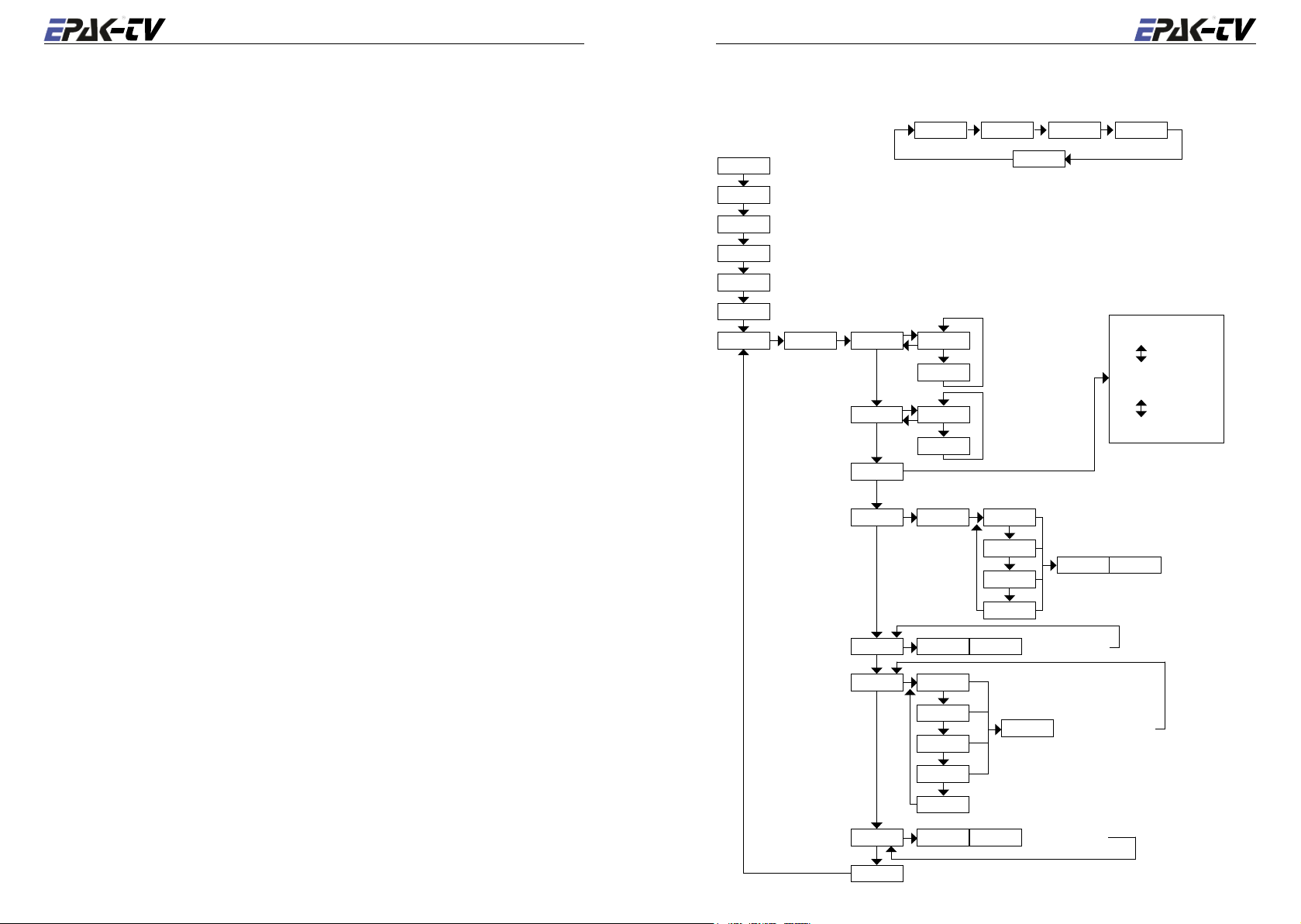
B Overview of menu structure
serial no.
XXXXXXX T XXXXX VA X-XX VC X-XX
Standby
AutoSat
6)
8)
searches and tracks stored satellite (Sat 1...4 will be selected by receiver)
2)
Sat 1
Sat 2
Sat 3
Sat 4
Setup ---- Tracking On
searches and tracks stored satellite 1
2)
searches and tracks stored satellite 2
2)
searches and tracks stored satellite 3
2)
searches and tracks stored satellite 4
password
request
FastScan
LNB Type
Off
Off
settings of LNB-type and skew (angle)
1) 5)
New Sat ScanBand? Band 1
On
counter
operation time
Standby
tracking of stored
satellite
durring searching
of stored satellites
software version
antenna unit
9)
software version
control unit
LIN -70
LIN -60
LIN -10
LIN 0
LIN +10
LIN +20
LIN +70
Circular
(Standard)
1) Always possible, as long as free satellite storage positions are available.
2) Only shown in the display if the respective satellite storage position is occupied.
3) Only the occupied satellite storage positions are shown.
4) Confirm function by pressing
, abandon by pressing .
5) Function has to be carried out in the harbor in calm waters.
6) Standby mode can quickly be reached from all menus by short press on the
key.
7) Display flashes.
8) TV46/60 models only, when at least one satellite is stored and the receiver supports this feature
(DiSEqC™).
9) Special functions in standby mode.
Upd Sat UpDate? Sat X
3)
Del Sat Sat 1
Sat 2
Sat 3
Sat 4
cancel
Comp Cal UpDate? Compass
quit
2)
2)
2)
2)
Band 2
Band 3
Band 4
Delete?
Search? New Sat
7)
searching new satellite
update satellite data
4)
deletes selected satellite
5)
calibrate compass
28 English
English 29
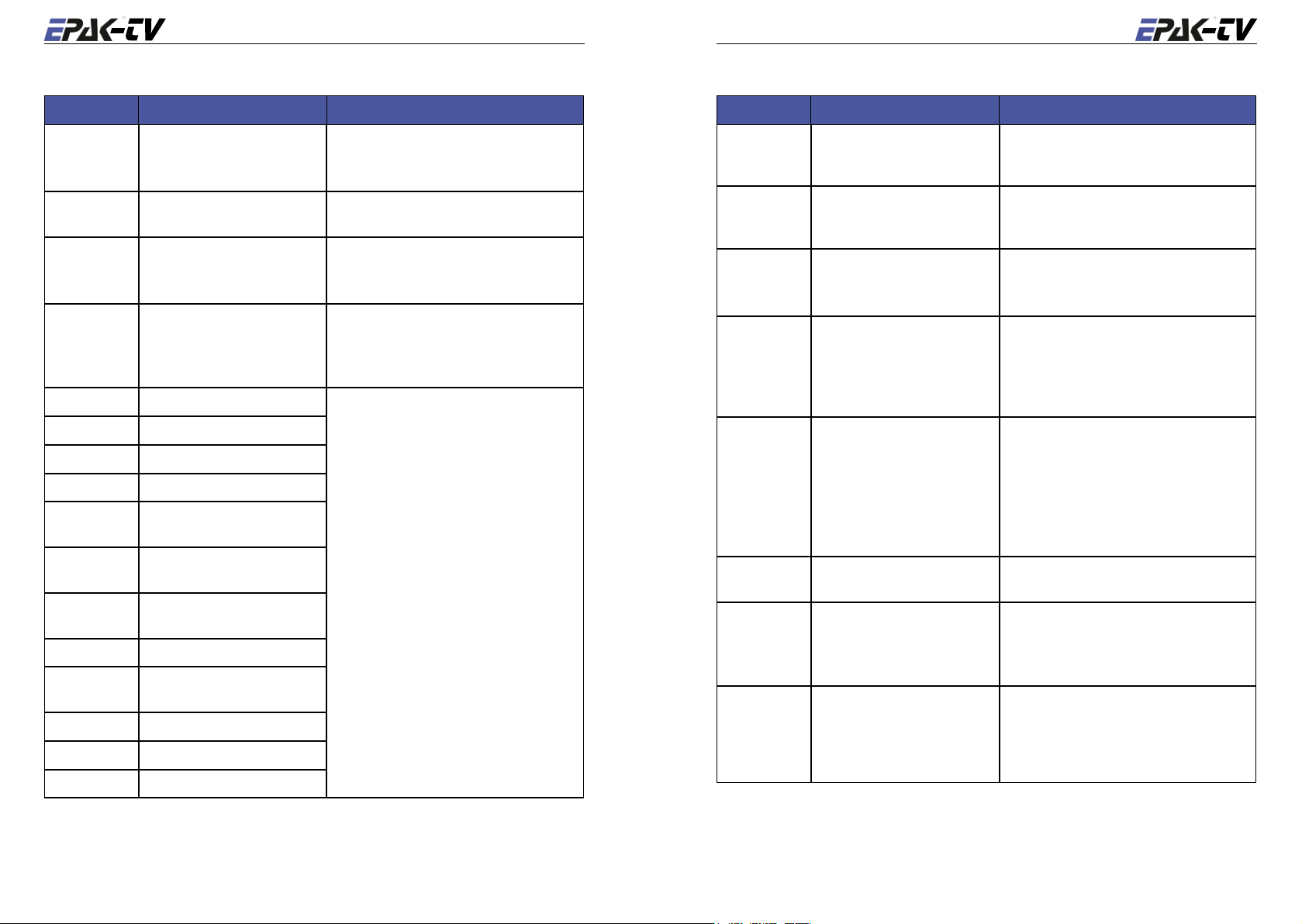
C Troubleshooting
Display Problem Remedy
no dish
ErrorCom
Low Batt
no Data
Err HR
Err HW
Err VR
Err VW
Err SR
Err SW
Err VCO
Err EEP
Err IIC
Err Trck
Err ULS
Err LLS
No connection to the antenna
unit
Communication error with
antenna unit
Power supply too low (>11.5V) - Check power supply connection for anten-
The satellite position requested
by the receiver in
mode is not stored in antenna
unit
Read error of horizontal unit Turn the unit off and on again. In case the
Write error of horizontal unit
Read error of vertical unit
Write error of vertical unit
Read error of signal processing unit
write error of signal processing unit
Error during satellite inspection
Error during storage
Error in internal communication
Error in tracking module
Error in upper limit switch
Error in lower limit switch
Auto Sat
- Check cable connection to antenna unit
(power and antenna cable)
- Check antenna unit’s power supply
Turn unit off and on again
na unit (loose cable)
- Charge battery
- Check the DiSEqC™ adjustment of the
receiver
- Add satellite and store position (see sec
tion 4.1)
error reoccurs, call for technical assistance.
Display Problem Remedy
Err Comp
Err Save
complete
Sat
X inter-
-
changing with
no Sig
scanning
interchanging
with
com-
plete
Compass error Compass will automatically reset and recal-
librate. In case the error reoccurs several
times, call for technical assistance.
Error while saving satellite Repeat search and storing procedure. Make
sure the boat is not moving and no super
structures obstruct the sight to the satellite
The search for a stored satellite
was successful, but no picture
is shown
No reception of the stored satellite
No receptable satellite in the
entire search range
Cannot find a satellite - Check, if superstructures obstruct the view
Cannot find a stored satellite - Check, if superstructures obstruct the view
Search for stored satellite takes
longer, even though there are
no obstructions in the view to
the satellite
- Deactivate Fastscan mode
- Delete satellite storage positions and
memorize again
- Check if superstructures (e.g. steeple cab
or masts of proximate boats) obstruct the
sight to the satellite − if so, move the boat
- Reception can be briefly interrupted by
passing boats
- Check, if the program selected on the re
ceiver is transmitted by the wanted satellite
- Check, if any superstructures are obstruct
ing the sight to the satellite
- Check, by using footprint cards (e.g. www.
satcodx.com), that the boat is inside the cov
erage area (footprint)
to the satellite, and restart the search mode
to the satellite
- Delete the stored satellite and restart the
search mode
If the location of the vessel changes, the an
gles of the satellite may have moved. Modi
fy angles of the satellite at the new location
with the function
4.2.
Upd Sat
, see section
-
-
-
-
-
-
30 English
English 31
D Replacement parts
• Electronic box
• LNB
• Sensor and limit switch unit
• Control unit
Two User on Twin EU Antenna
Both receivers have independent access to all TV channels from all 4 bands. Can switch antenna
on/off. Only master can change sat-position.
Multi User on Twin EU Antenna
All receivers have independent access to all TV channels from two of the four bands. Can switch
antenna on/off. Only Control Unit can change sat-position.
– see illustration, Fig. 3, end of manual:
– see illustration, Fig. 4, end of manual:
E Optional parts
• LNB mounting with variable skew
All parts are available from you local authorized dealer/installer.
☛ Unauthorized attempts made to open the radome will void any warranty claims.
F System overview
General cable data
Type 1 Double shielded satellite coax cable (75 Ohms) with F-connectors (one-wire).
Type 2 Double shielded satellite coax cable (75 Ohms) with F-connectors
(five-wire in one coating).
Type 3 AV cable or Antenna cable (depends on user’s installation).
Type 4 Power cable (min. 2 x 1.5 sqmm), max. length 15 meters.
Single User on Single EU Antenna
One receiver has independent access to all channels of all 4 bands. Can switch antenna on/off.
Can change sat-position.
– see illustration, Fig. 1, end of manual:
Multi User on Quattro EU Antenna
All receivers have independent access to all TV channels of all 4 bands. Can switch antenna on/
off. Only Control Unit can change sat-position.
– see illustration, Fig. 5, end of manual:
G Elevation angles
Area Sirius Hotbird Astra Turksat
Antalya 39° 43° 45° 47°
Athens 41° 44° 45° 45°
Balaton 31° 34° 35° 36°
Barcelona 42° 40° 39° 33°
Batumi 28° 39° 36° 40°
Bordeaux 38° 33° 34° 29°
Bornholm 26° 36° 27° 25°
Burgas
Constanta 34° 37° 39° 39°
Copenhagen 26° 26° 26° 24°
Cork 28° 26° 24° 19°
Corsica 41° 41° 40° 36°
36° 27° 40° 40°
Multi User on Single EU Antenna
The master receiver has independent access to all channels of all 4 bands. Can switch antenna on/
off. Can change sat-position. All slave receivers have access to all TV channels from the one band
at the satellite, selected by the master receiver.
– see illustration, Fig. 2, end of manual:
Crete 45° 48° 49° 49°
Crimea 30° 34° 36° 38°
Cyprus 40° 45° 47° 50°
32 English
English 33
Area Sirius Hotbird Astra Turksat
Edinburgh 25° 24° 23° 19°
Gdansk 26° 27° 28° 26°
Gibraltar 46° 43° 40° 33°
Helsinki 19° 21° 21° 21°
Istanbul 36° 39° 41° 42°
Kiel 27° 27° 27° 25°
Lisbon 42° 39° 36° 28°
Majorca 44° 43° 41° 35°
Malta 47° 48° 48° 44°
Marseilles 40° 39° 38° 33°
Naples 42° 43° 42° 39°
Palermo
45° 45° 45° 41°
Plymouth 29° 28° 26° 21°
Rhodes 41° 45° 47° 48°
Riga 24° 26° 27° 26°
Rome 41° 41° 41° 38°
Rotterdam 30° 30° 30° 25°
Sardinia 43° 43 42° 38°
Split 35° 38° 39° 40°
Stockholm 21° 22° 22° 21°
Thessaloniki 39° 41° 42° 41°
Trondheim 18° 18° 18° 16°
Venice 37° 37° 37° 34°
Wilhelmshaven
28° 28° 27° 25°
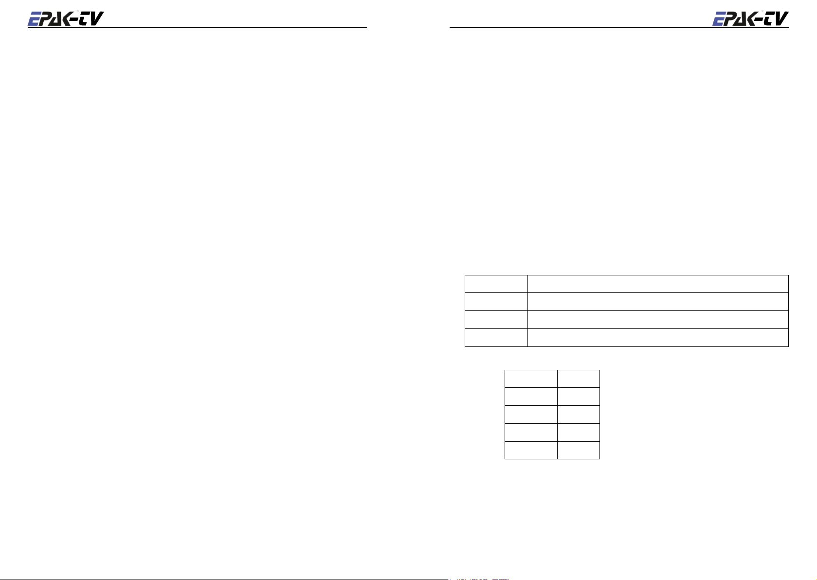
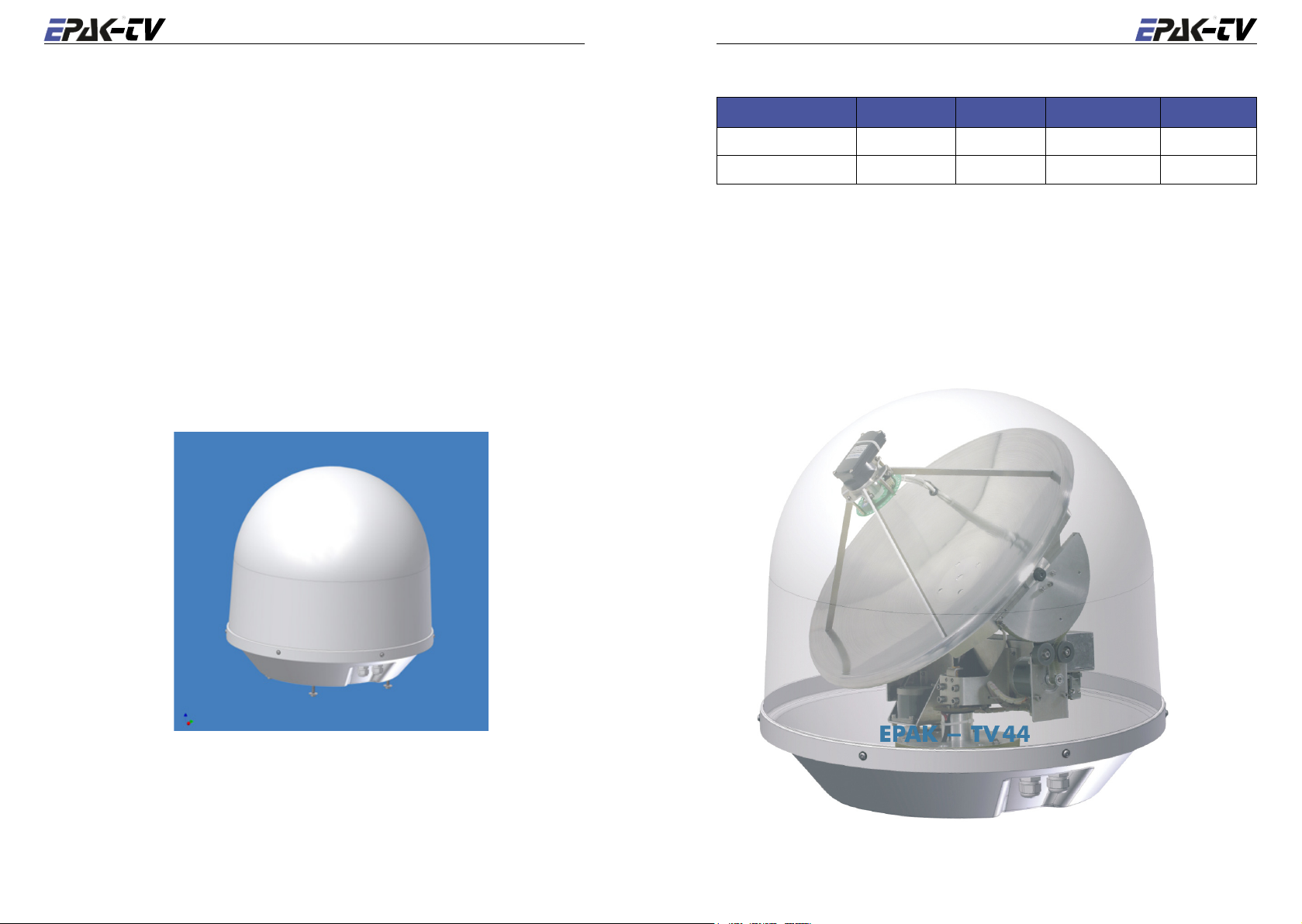
H Technical specifications
Antenna unit TV44 TV59
Type Prime Focus
Diameter 45 cm (17.7") 60 cm (23.6”)
Gain 33 dB 34.8 dB
Minimum E.I.R.P.*
tion of geostationary satellites)
LNB (US) LH/RH circular
LNB (EU) H/V linear, Universal
Radome diameter 510 mm 710 mm
Radome height 530 mm 690 mm
Weight (incl. radome) 12 kg 16 kg
Azimuth range unlimited
Elevation range
Step width 0.1°
Drive system two-axis servo system
Tracking Sensor Electronic Beam Forming (EBF)
Tracking range unlimited (within the horizontal and vertical range)
Positioning speed >35 °/s
Tracking speed
ment of ship)
Power supply 12 to 36 VDC, 10 to 20 W
Power on satellite lock time 10 s (typ.), 20 s (max.)
Control unit TV44 TV59
Power supply 12 to 20 VDC, 100 mA (via coax cable)
Satellite acquisition fully automatically by SatFingerprint Technology
Satellite positions up to 2 freely pro-grammable positions (4 optional)
Selection of programmed
satellites
System TV44 TV59
Operation temperature –20 to +70 °C
Storing temperature –30 to +85 °C
(for recep-
(at every move-
50 dBW 48 dBW
5..85° 0..90°
>30 °/s
by control unit

HANDBUCH
Basic Line
TV44 & TV59
Deutsch

36 Deutsch
Deutsch 37
Inhalt
1 Das digitale Satellitenempfangssystem .............................................................38
1.1 EPAK®-TV Systemüberblick .........................................................................39
1.2 Sicherheitshinweise ........................................................................................40
2 Installation ...........................................................................................................41
2.1 Lieferumfang ..................................................................................................41
2.2 Die Installation im Überblick .........................................................................41
2.3 Wahl des Standortes .......................................................................................42
2.4 Montageuntergrund ........................................................................................ 43
2.5 Planung der Kabelwege .................................................................................43
2.6 Stromversorgung ............................................................................................ 43
2.7 Bohrungen ...................................................................................................... 43
2. 8 Montage der Antenneneinheit ........................................................................ 45
2. 9 System Kabelverbindungen ...........................................................................45
3 Bedienelemente ...................................................................................................46
3.1 Bedieneinheit .................................................................................................46
5.3 Löschen von gespeicherten Daten .................................................................54
5. 4 Auswahl gespeicherter Satelliten ...................................................................54
5. 4.1 Manuelle Satellitenwahl ....................................................................... 54
6 Verschiedenes ......................................................................................................56
6.1 Kompasskalibrierung .....................................................................................56
6.2 Einstellung des LNB-Typs .............................................................................56
6.3 Sonderfunktionen im Standby-Modus ........................................................... 57
6.4 Fastscan-Modus (nur USA) ...........................................................................57
ANHANG
A Wartung .................................................................................................................58
B Überblick über die Menü-Struktur ........................................................................59
C Fehlermeldungen und -beschreibungen ................................................................60
5. 4.2 Automatische Satellitenwahl ................................................................55
3.2 Vorbereitung des Receivers ............................................................................46
3. 3 Ein- und Ausschalten der Antenneneinheit ....................................................47
3.4 Passwort für den Zugang zum Setup-Menü ................................................... 47
3.5 Einstellung der Setup-Parameter ....................................................................47
4 Fernsehbetrieb ....................................................................................................49
4.1 Tracking-Modus im Hafen ausschalten .........................................................50
5 Satelliten ..............................................................................................................51
5.1 Hinzufügen neuer Satelliten ...........................................................................51
5.2 Aktualisieren der Satellitendaten ................................................................... 53
D Austauschbare Teile .............................................................................................. 62
E Optional erhältliche Teile ......................................................................................62
F Systemüberblick ...................................................................................................62
Kabeldaten: ...........................................................................................................62
H Technische Spezifikationen ..................................................................................65
Systemüberblick Schaltpläne......................................................................................133
38 Deutsch
Deutsch 39
1 Das digitale Satellitenempfangssystem
1.1 EPAK®-TV Systemüberblick
Das Satellitenempfangssystem EPAK-TV ermöglicht Ihnen durch modernste Technik uneingeschränkten Fernsehgenuß. Durch ein unbegrenztes Rundum-High-Speed-Tracking garantiert es
selbst während der Fahrt auf offener See einen unterbrechungsfreien Empfang Ihrer Lieblings
sender.
Das Satellitenempfangssystem ist durch ein UV- und seeklimabeständiges Radom geschützt und
ist in seiner Handhabung so einfach wie in seiner Wartung. Die eigens für dieses System ent
wickelte Hochgeschwindigkeitssensorik übernimmt mittels Hightech-Komponenten der elektro
nischen Signalverarbeitung die exakte und hochdynamische Zielverfolgung des Satelliten. Mit
Hilfe dieser Technologie gewährleistet das System EPAK-TV eine bisher unerreichte Nachführ
geschwindigkeit, Dynamik und Systemgüte.
EPAK-TV eignet sich für Yachten jeder Größe und kann selbst auf kleineren Booten von weniger
als 11 m (36 ft.) Länge eingesetzt werden. Das automatische Satellitenempfangssystem EPAK-TV
verfügt über eine Reflektorantenne mit 45 cm bzw. 60 cm Durchmesser, welche in zwei Achsen
horizontal und vertikal durch Direktservoantriebe (außer Modell TV45) nachgeführt wird. Somit
wird eine Fernsehempfangsqualität und Programmvielfalt beinahe wie zu Hause möglich. Ist der
Satellit erst einmal lokalisiert, verfolgt das Antennensystem diesen punktgenau, auch unter rauhen
maritimen Bedingungen.
Modell Single Multi Receiver Bänder
-
-
-
-
TV44 x 1 4
TV59 x 1 4
• Bei Single Antennen mit mehr als einem Receiver, empfangen alle Receiver das gleiche Band.
Wenn also der Master Receiver auf ein anderes Band schaltet, empfangen alle anderen Receiver
dieses neue Band ebenfalls.
Hinweis! Zu den Empfangsmöglichkeiten einzelner Programme in verschiedenen
Regionen beachten Sie bitte die Ausleuchtzonen der verschiedenen Fernsehsa
telliten. Bitte beachten Sie weiterhin, daß viele Faktoren wie z. B. Regen, Schnee
und dichte Wolken den Fernsehempfang in den Randbereichen der Satelliten
ausleuchtzone beeinflussen können.
-
-

40 Deutsch
Deutsch 41
1.2 Sicherheitshinweise
2 Installation
➤ Beachten Sie die zulässige Betriebsspannung der Antenneneinheit. Sie muß zwischen 12 V=
und 36 V= liegen und ist mit mind. 5 A und max. 7, 5 A abzusichern.
➤ Der Montageabstand der Antenneneinheit zu anderen Strahlungsquellen (wie z. B. Radaranla
gen oder anderen Antennen (Mobilfunkantennen) muß mind. 2,5 m betragen.
➤ Ein gleichzeitiger Betrieb von Radar und Satellitenantenne kann die Satellitenantenne beschä
digen, wenn diese nicht direkt über der Radarantenne montiert ist.
Die Bedieneinheit darf nur in geschlossenen Räumen betrieben werden.
➤
➤ Während eines Gewitters müssen die Anschlußleitungen abgetrennt werden.
➤ Sollte der Minuspol der Betriebsspannung der Antenne nicht mit der Bootsmasse verbunden
sein, so ist der Erdungspunkt der Antenneneinheit direkt zur Bootsmasse zu verbinden.
➤ Nach der Installation der Antenne sind bei laufender Antenne alle anderen Funksysteme (GPS,
Radar, FM, AM ...) auf volle Funktion zu überprüfen.
➤ Die Antenne nicht testen oder betreiben, wenn das Radom nicht korrekt montiert ist. Reflek
tierte Sonnenlichteinstrahlung im Spiegel kann die Elektronik beschädigen.
➤ Die Drehverbindung nicht berühren.
➤ Versuchen Sie nicht, die versiegelte Elektronik-Box zu öffnen. Dies würde zu einem Verlust
Ihres Gewährleistungsanspruchs führen.
2.1 Lieferumfang
Das Satellitenempfangssystem EPAK-TV umfaßt die Antenne, das Bedienteil, die Kabel und das
-
-
Installationsmaterial.
Systemkomponenten:
• Antenneneinheit (mit Seriennummer)
• Bedieneinheit
• Vier Montageschrauben M8
☛ Bitte kontrollieren Sie alle Komponenten auf Vollständigkeit. Vergewissern Sie sich, daß kei-
ne Transportschäden vorliegen, bevor Sie mit der Installation beginnen.
2.2 Die Installation im Überblick
Der Aufbau des Satellitenempfangssystems ist in folgender Reihenfolge durchzuführen:
• Standort aussuchen
• Montageuntergrund auf Stabilität prüfen
• Kabelwege prüfen
-
• Lage des Stromverteilers
• Löcher bohren und Kabel verlegen
• Montage der Antenneneinheit (Beachten Sie unbedingt die Instruktionen zum Entfernen
der Transportsicherung vor
• Wasserdichtes Verschließen aller Montageöffnungen
• Kabel anschließen
Zur Installation des Satellitenempfangssystems werden mindestens folgende
Werkzeuge benötigt:
• Bohrmaschine
• Bohrer mit ø 4mm und ø 8,5mm – 9mm
• Innensechskant Schlüsselgröße 6
• Schraubenschlüssel M8
Inbetriebnahme!)
☛ Planen Sie die Installation zuerst! Bitte lesen Sie die Installationsanleitung genau durch,
bevor Sie mit dem Aufbau beginnen, um mögliche Fehler und Beschädigungen an Boot bzw.
Satellitenempfangssystem zu vermeiden!
 Loading...