

EPAK Premium Line TV61TV90, Premium Line TV61 User Manual

MANUAL
Premium Line TV61 & TV90
English
1

MANUAL
Premium Line TV61 & TV90
English
The technical data, information and illustrations contained in this publication were to the best of our
2

knowledge correct at the time of printing. No liability can be accepted for any inaccuracies or
omissions in the publication, although every care has been taken to make it as complete and accurate
as possible.
v3
Table of Contents
1 The digital satellite tracking system...................................................................................................4
1.1 EPAK®-TV system overview........................................................................................................5
1.2 Safety recommendations................................................................................................................6
2 Installation............................................................................................................................................7
2.1 Standard delivery............................................................................................................................7
2.2 Installation overview......................................................................................................................7
2.3 Selecting location...........................................................................................................................8
2.4 Mounting surface............................................................................................................................9
2.5 Planning the cable paths.................................................................................................................9
2.6 Power supply..................................................................................................................................9
2.7 Drillings..........................................................................................................................................9
2.8 Mounting the antenna unit............................................................................................................12
2.9 System cable connections.............................................................................................................12
3 Control elements.................................................................................................................................13
3.1 Control unit...................................................................................................................................13
3.2 Preparing the receiver...................................................................................................................13
3.3 Power On, Off and Standby.........................................................................................................13
3.4 Password access to Setup menu...................................................................................................14
3.5 Adjusting the setup parameters....................................................................................................14
4 TV operation.......................................................................................................................................15
4.1 Stop Tracking function in harbors................................................................................................16
5 Satellites...............................................................................................................................................17
5.1 Adding new satellites...................................................................................................................17
5.2 Update of satellite data base.........................................................................................................18
5.3 Delete stored data.........................................................................................................................19
5.4 Selection of stored satellites.........................................................................................................20
5.4.1 Manual selection of satellites................................................................................................20
5.4.2 Automatic selection of satellites...........................................................................................20
6 Miscellaneous......................................................................................................................................21
6.1 Compass calibration.....................................................................................................................21
6.2 Adjustment of the LNB type........................................................................................................22
6.3 Special functions via the standby mode.......................................................................................22
6.4 Fastscan function (US only).........................................................................................................23
APPENDICES.......................................................................................................................................24
A Maintenance.......................................................................................................................................24
B Overview of menu structure.............................................................................................................25
C Troubleshooting.................................................................................................................................26
D Skew settings......................................................................................................................................27
E Tracking Modes.................................................................................................................................28
F Replacement parts.............................................................................................................................28
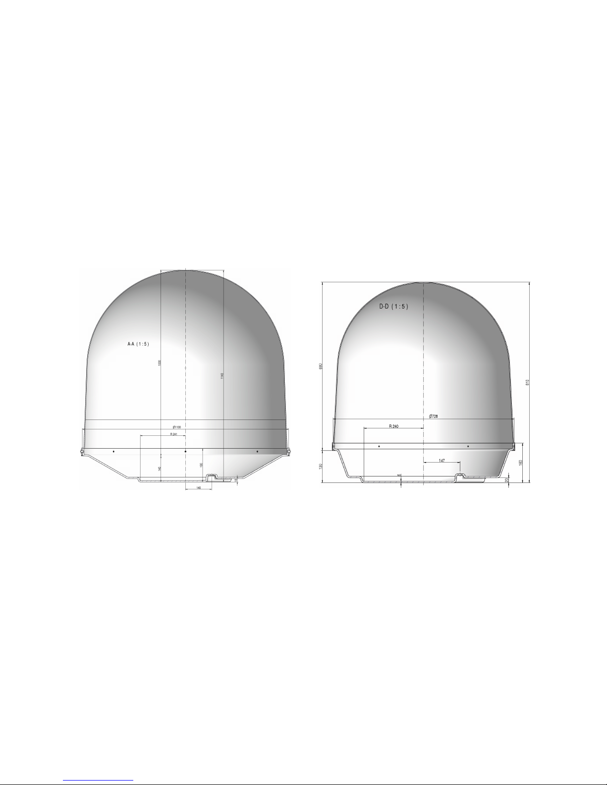
G Technical specifications....................................................................................................................29
3
1 The digital satellite tracking system
The advanced technology in the satellite tracking system EPAK-TV makes it possible to have an
excellent television reception wherever you are. Due to an unlimited 360° high-speed tracking, a nonstop access to your favorite channels is guaranteed even during your trip on a vessel in open seas.
The satellite tracking system is protected by a UV-stabilized and maritime climate proof radome, easy
to handle and maintain. (Please note that the given warranty for the radome is limited to the terms of
the radome manufacturers. Please see details on www.epak.de/download/radome_warranty.pdf) Highspeed tracking sensors developed for this system, using high-tech components of the electronic signal
processing, provide the topmost and dynamic tracking accuracy of the satellite tracking system. With
the help of this technology, EPAK-TV guarantees an unmatched tracking rate, dynamic and system
performance. EPAK-TV is suitable for any size vessel including smaller boats of less than 36ft (11m).
The automatic satellite tracking system includes a reflector antenna dish of 18" (45cm), 24" (60cm) or
35" (90cm) in diameter that is capable of tracking horizontally and vertically to make an amazing
choice of channels available – just like home.
Once the connection to a satellite is established, the tracking system will stay connected to the correct
satellite even in the roughest sea conditions.
TV90 TV61
Notice! Don’t use alcohol or dilution or similar products for cleaning the radome!
Note! The reception of programs in different regions depends on the footprints of the satellites.
Also, the TV reception can be affected by rain, snow, dense clouds and extreme movements in
areas of weak signals and there is no warranty for receiption of certain channels.
4
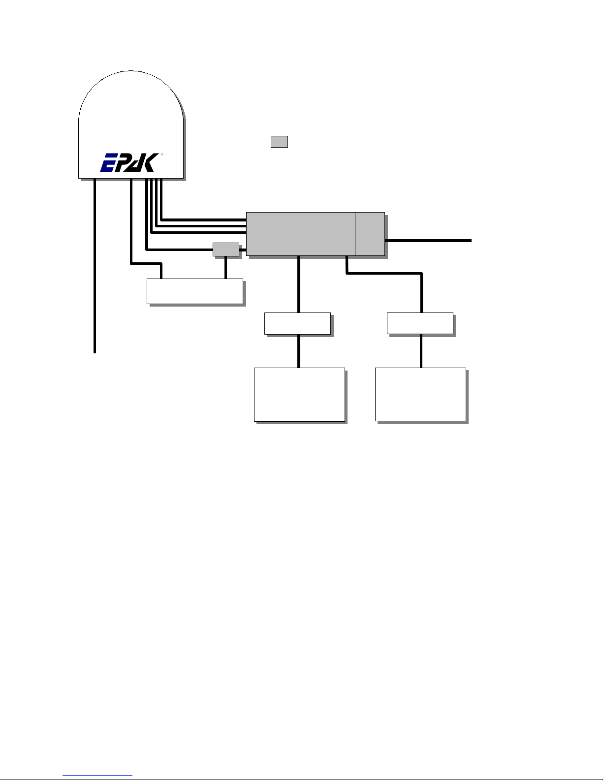
1.1 EPAK®-TV system overview
Multi User configuration with Quattro EU Antenna
All receivers have independent access to all TV channels of all 4 bands. Can switch antenna on/
off. Only Control Unit can change sat-position.
Type 1 Double shielded satellite coax cable (75 Ohms) with F-connectors (one-wire).
Type 2 Double shielded satellite coax cable (75 Ohms) with F-connectors (five-wire in one coating).
Type 3 AV cable or Antenna cable (depends on user’s installation).
Type 4 Power cable (min. 2 x 1.5 sqmm), max. length 15 meters.
5
Antenna
Multiswitch
Antenna Power
12 to 36 VDC
Type 4
Receiver 1
TV 1
...
Receiver n
TV n
Type 1
Type 1
Type 1
Type 3
Type 3
HV
HH
LV
LH
Control Unit
ReceiverAntenna
Power
Supply
Power 220VAC
(Power cord included)
Bias
Part of Multiuser-Kit

1.2 Safety recommendations
➔ Please note that the maximum power voltage for the antenna unit must be between 12 and 36
volts DC, and the overload protection should be rated min. 5 amp. and max. 7.5 amp.
➔ When mounting the antenna, the distance from the antenna unit to other radiation sources e.g.
radar equipment or other antennas (mobile communication antennas) should be min. 2.5 m (8
ft).
➔ Simultaneous operation of radar and satellite antenna may damage the satellite antenna if not
installed directly above the radar antenna.
➔ Do not use the control unit outdoors.
➔ During a thunderstorm, we recommend that the connection cables are disconnected.
➔ If the negative side of the antenna unit’s supply voltage has no connection to ship’s ground
(earth), then the antenna unit’s ground point should be connected directly to ship’s ground
(earth).
➔ After the installation is completed, all other electronic systems i.e. GPS, Radar, VHF, FM, AM
etc. should be tested for full functionality, while the antenna is turned on.
➔ Do not test or turn on the antenna before the radome is fitted correctly. If the sun reflects into
the dish, the electronics can be damaged.
➔ Do not touch the rotary joint.
➔ Do not attempt to open the sealed electronics, as this will void the warranty.
6

2 Installation
2.1 Standard delivery
The satellite tracking system EPAK-TV comes complete with electronic assemblies and other
necessary installation material.
System components:
● Antenna unit (with serial number)
● Control unit
● Four mounting screws M 8
● Manual
Please check the completeness of all components. Make sure that no transport damages exist before
you start the installation.
2.2 Installation overview
The installation work has to be done in the following order:
● Select location
● Check the mounting surface for stability
● Check cable path
● Position of power distributor
● Drill holes and lay the cable
● Install antenna unit (see also addendum for instructions of how to remove the transportation
lock before power-up)
● Make all installation openings watertight
● Connect cables
For the installation the following tools are needed:
● Electric drill
● One 4mm and one 8.5-9 mm bits
● Hexagon socket wrench size 6
● Wrench M 8
☛ Plan the entire installation first! To avoid mistakes or damages to the boat or satellite tracking
system, please read the installation instructions carefully before starting the installation.
7
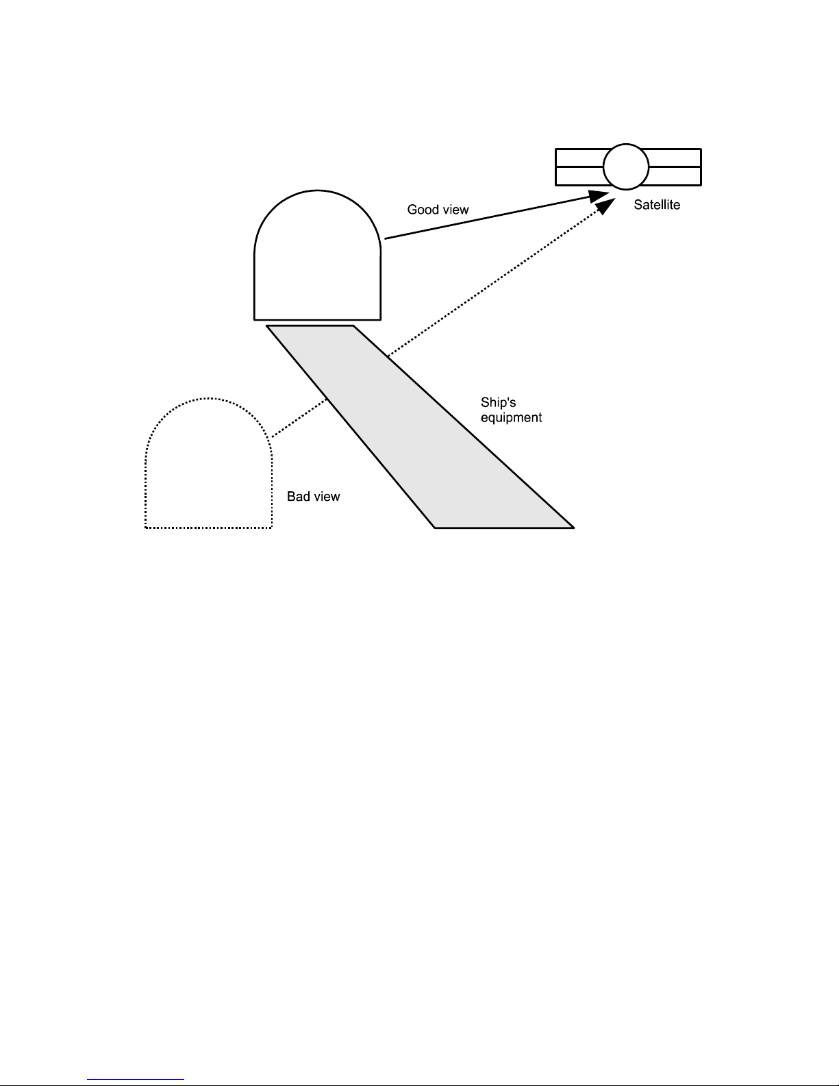
2.3 Selecting location
This illustration shows the importance of a proper location for the antenna unit.
Note that criteria such as an unobstructed view to the satellite and a strong mounting surface are met.
Furthermore, no sources of interference, e.g. radar equipment or other antennas, such as mobile
communication antennas, should be installed nearby the Marine TV antenna unit. A minimum distance
of 8-12 ft. (2-3 meters) has to be observed in order not to affect the picture quality.
Although the radome is sealed, it is recommended to avoid direct waves and bilge water!
The antenna unit has to be installed so that no superstructures will obstruct the sight to the satellite!
Please note, that the elevation angle depends on the geographical location of the boat and on the
selected satellite!
☛ Equally important for a good installation are the conditions of the mounting surface and the
lengths of the different cables. See section 2.4, 2.5 and 2.6.
8
Antenna
Antenna

2.4 Mounting surface
A horizontal, solid and steady surface is very important. Make sure that the surface does not have any
irregularities! Furthermore, please take into consideration that the weight of the antenna unit is 56 kg
or more. Therefore, the surface has to be strong enough to carry the antenna unit, even during the most
challenging maritime conditions.
2.5 Planning the cable paths
Before starting the installation, you should check which walls are suitable and if existing openings can
be used for the cables.
☛ All openings have to be sealed in order to avoid any water penetrating.
The control unit should be placed as close as possible to the receiver. The maximum length of the
cable is 3 meters. Refer to Appendix F for data concerning appropriate cable types.
2.6 Power supply
The antenna unit can be connected directly to any ship’s power supply net of 12/24/32 volts DC. The
circuit fuse should be rated for min. 5 amperes and max 7.5 amperes! (See appendix H “Technical
Specifications”).
☛ The power distributor must be idle while working on the ship’s supply net or you may short
circuit the system.
If the negative side of the supply voltage of the antenna unit has no connection to the boat ground,
make sure a potential compensation between boat ground and the ground point of the antenna unit is
made.
2.7 Drillings
To avoid any damage to the mounting surface it is recommended that you start out with drilling a
smaller hole, using a 3.5-4 mm bit before drilling the correct hole size. Use an 8.5-9 mm bit to drill 4
mounting holes for the M8 screws included. To drill the holes in the correct positions, please refer to
the included template.
9
 Loading...