

EPAK River Line, TV43, TV58, Basic Line, TV44 Series Manual
...
Manual
River Line
TV43 & TV58
Basic Line
TV44 & TV59
Premium Line
TV61 & TV90
English V2.08 / 2010
Manual
River Line
TV43 & TV58
Basic Line
TV44 & TV59
Premium Line
TV61 & TV90
The technical data, information and illustrations contained in this publication were to the best of our knowledge
correct at the time of printing. No liability can be accepted for any inaccuracies or comissions in the
publication, although every care has been taken to make it as complete and accurate as possible.
English Page 2 / 34

Contents
1. The digital satellite tracking system...............................................................................................4
1.1. EPAK®-TV system overview...........................................................................................................................................................4
1.2. Safety recommendations................................................................................................................................................................5
2. Installation.........................................................................................................................................6
2.1. Standard delivery............................................................................................................................................................................6
2.2. Installation overview........................................................................................................................................................................6
2.3. Selecting location............................................................................................................................................................................6
2.4. Mounting surface.............................................................................................................................................................................7
2.5. Planning the cable paths.................................................................................................................................................................7
2.6. Power supply...................................................................................................................................................................................7
2.7. Drillings...........................................................................................................................................................................................8
2.8. Mounting the antenna unit.............................................................................................................................................................11
2.9. System cable connections.............................................................................................................................................................11
3. Control elements.............................................................................................................................12
3.1. Control unit....................................................................................................................................................................................12
3.2. Preparing the receiver...................................................................................................................................................................12
3.3. Power on / off / Standby................................................................................................................................................................12
3.4. Password access to Setup menu..................................................................................................................................................13
3.5. Adjusting the Setup parameters....................................................................................................................................................13
4. TV operation....................................................................................................................................14
4.1. Stopping the Tracking function in harbours...................................................................................................................................15
5. Satellites...........................................................................................................................................15
5.1. Adding new satellites.....................................................................................................................................................................15
5.2. Update of satellite data base.........................................................................................................................................................18
5.3. Delete stored data.........................................................................................................................................................................18
5.4. Selection of stored satellites.........................................................................................................................................................19
5.4.1. Automatic selection of satellites............................................................................................................................................19
5.4.2. Manual selection of satellites................................................................................................................................................19
6. Miscellaneous..................................................................................................................................20
6.1. Adjustments of LNB- type..............................................................................................................................................................20
6.2. Special functions via the Standby mode.......................................................................................................................................20
6.3. Fastscan function (US only)..........................................................................................................................................................21
7. APPENDICES...................................................................................................................................21
7.1. Maintenance..................................................................................................................................................................................21
7.2. Overview of menu structure..........................................................................................................................................................22
7.3. Troubleshooting.............................................................................................................................................................................23
7.4. Skew settings................................................................................................................................................................................25
7.5. Replaceable parts.........................................................................................................................................................................25
7.6. Optional parts................................................................................................................................................................................25
7.7. System overview...........................................................................................................................................................................25
7.7.1. General cable data...............................................................................................................................................................25
7.7.2. Single User on Single EU Antenna.......................................................................................................................................26
7.7.3. Multi Users on Single EU Antenna.......................................................................................................................................27
7.7.4. Two Users on Twin EU Antenna...........................................................................................................................................28
7.7.5. Multi Users on Twin EU Antenna..........................................................................................................................................29
7.7.6. Multi Users on Quattro EU Antenna.....................................................................................................................................30
7.8. Elevation angles............................................................................................................................................................................31
7.9. Technical specifications.................................................................................................................................................................33
English Page 3 / 34
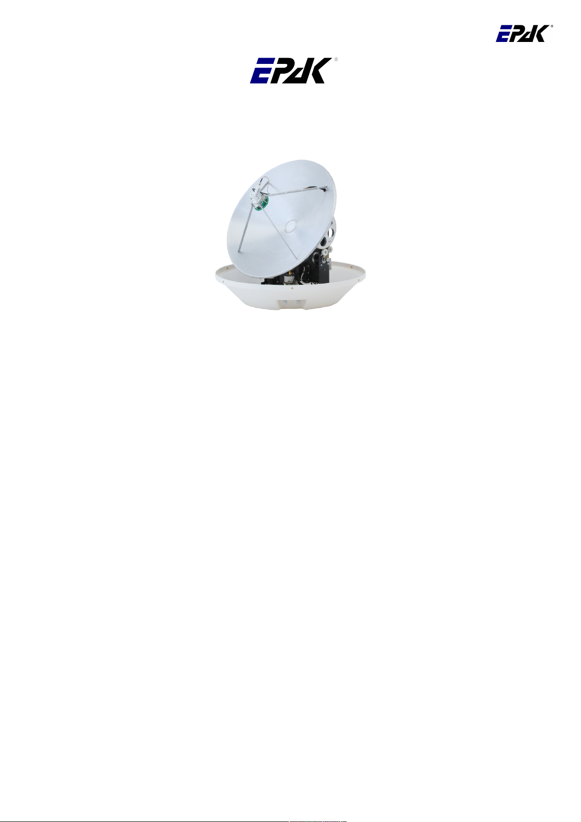
1. The digital satellite tracking system
The advanced technologies of the satellite tracking system EPAK-TV makes an excellent television
reception possible. An 360° high-speed tracking guarantees a non-stop reception of your favourite
channels even during your trip in open seas. Once the connection to a satellite is established, the tracking
system will stay connected to that satellite even in the roughest sea conditions.
The EPAK-TV system is suitable for vessels of any size including smaller boats of less than 36ft (11m).
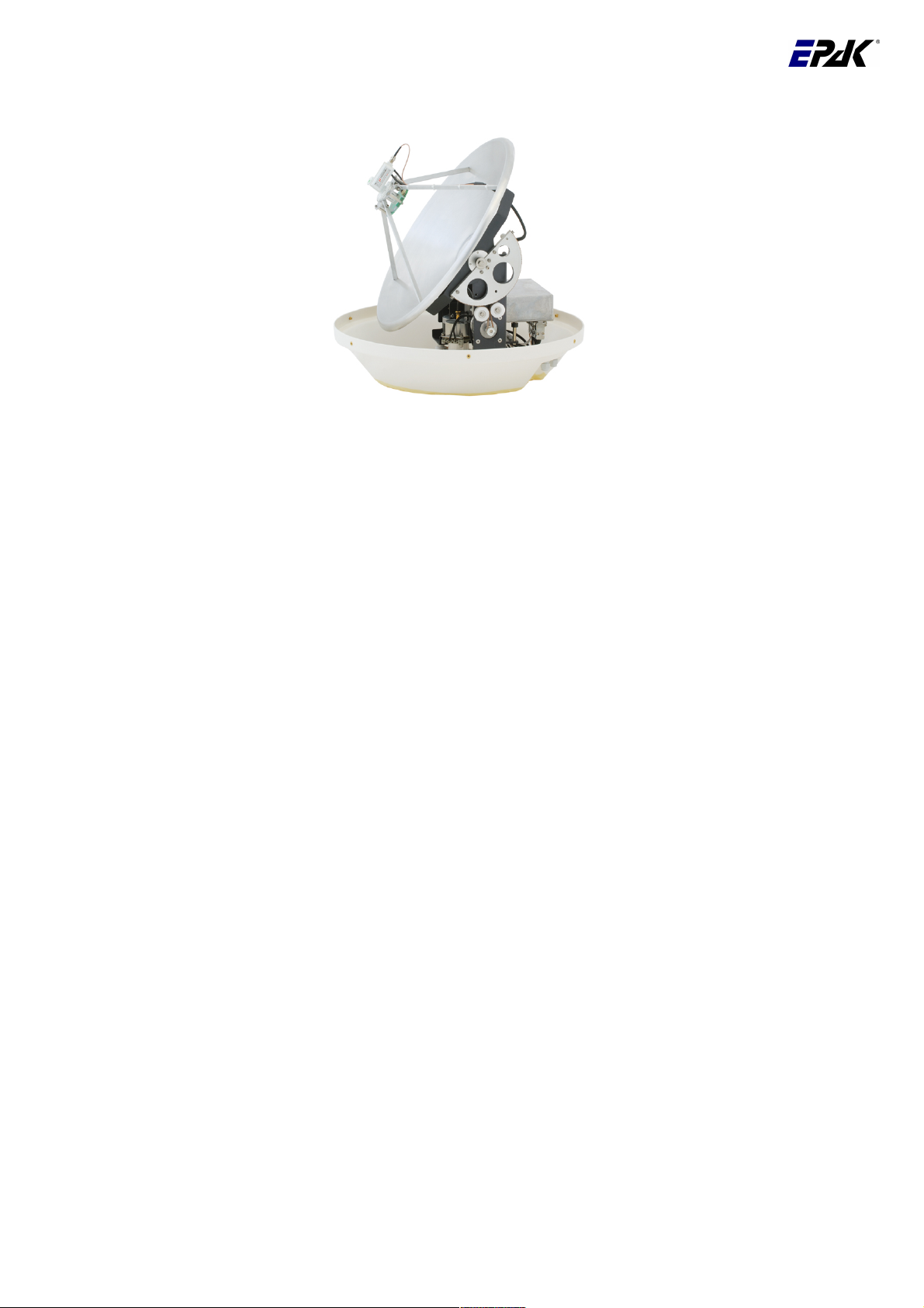
According to different tracking conditions of the respective region a choice between a reflector antenna
dish of 18'' (45cm), 23.6'' (60cm) and 35” (90cm) in diameter is neccessary. The antenna is capable of
tracking horizontally, vertically and in case of the Premium Line antennas also in polarization angle
(skew) due to its direct servo drive. We developed the patent-registered high-speed tracking sensors that
provide together with other high-tech components a topmost and dynamic tracking accuracy of a satellite.
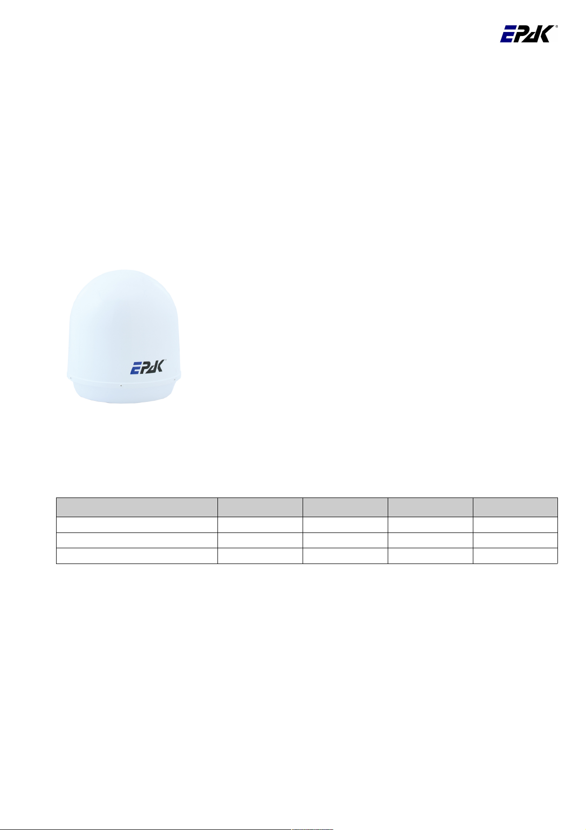
The TV-system is protected by a UV-stabilized and maritime climate proof radome.
To provide an unlimited reception of available channels – just like at
home, we attach great importance to high tracking stability and quality
as well as easy handling and maintenance.
Note! The reception of channels in different regions depends on the
footprints of the satellites. Also, the TV reception can be affected by
rain, snow, dense clouds and extreme movement thus there is no
warranty for the reception of certain channels.
Note!! Don't use alcohol, dilution or similar products for cleaning the
radome!
1.1. EPAK®-TV system overview
Models Single Twin Quattro Bands EU
TV 43 / TV 44 X X - 4
TV 58 / TV 59 X X X 4
TV 61 / TV 90 - - X 4
If you wish to use the respective antenna with one or more receivers, please check chapter 7.6.2 of the
manual.
English Page 4 / 34
1.2. Safety recommendations
1. Please consider the maximum allowable power voltage for the antenna unit. The DC voltage must be
between 12 and 36 volts and the overload protection should be rated at min. 5 amp. and max. 7.5
amp..
2. The mounting distance from the antenna unit to other radiation sources, e.g. radar equipment or other
transmitting antennas, should be at min. 2.5 m (8 ft).
3. If the satellite antenna is not installed above the radar antenna, simultaneous operation of both
systems may damage the satellite antenna.
4. Do not use the control unit outdoors!
5. During a thunderstorm, we recommend to disconnect all connection cables.
6. If the negative side of the antenna unit’s supply voltage has no connection to the ship’s ground (earth),
then the antenna unit’s ground point should be connected directly to the ship’s ground (earth).
7. After the installation is completed all other electronic systems, i.e. GPS, Radar, VHF, FM, AM etc.,
should be tested for full functionality while the antenna is turned on.
8. Do not test or turn on the antenna before the radome is fitted correctly. The electronics can be
damaged by the reflected sun.
9. Do not touch the rotary joint.
10. Do not open the sealed electronic box, as this will void the warranty.
English Page 5 / 34

2. Installation
2.1. Standard delivery
The satellite tracking system EPAK-TV comes complete with the antenna and the following system
components:
• Antenna unit (with serial number)
• Control unit
• Four mounting screws M 8
• Manual
Please check the completeness of all components. Make sure that no transport damages exist before you
start the installation.
2.2. Installation overview
The installation work has to be done in the following order:
• Select location
• Check the mounting surface for stability
• Check cable path
• Position of power distributor
• Drill holes and lay the cable
• Install antenna unit (see also addendum for instructions of how to undo the fixed transportation
position before power-up)
• Make all installation openings watertight
• Connect cables
For the installation at least the following tools are needed:
• Electric drill
• One 4mm and one 8.5-9 mm drill bits
• Hexagon socket screw key size 6 and 4
• 13mm screw wrench
Plan the entire installation first! To avoid mistakes or damages to the boat or satellite tracking system,
please read the installation instructions carefully before starting the installation.
2.3. Selecting location
The best location for the TV-antenna is a raised position on your ship. Thus, the needed unobstructed
view from the antenna to the satellite with the respective elevation angle can be established. In order not
to affect the picture quality or not to damage the antenna, please observe the minimum distance of 8-12ft.
(2-3 meters) to the radar equipment and other transmitting antennas! That includes mobile communication
units! If there is a radar antenna, the ideal location to mount the antenna will be right above the radar
antenna. Please also note that a strong mounting surface is needed and please avoid direct waves and
bilge water on the radome. For further details see chapters 2.4 – 2.9.
English Page 6 / 34
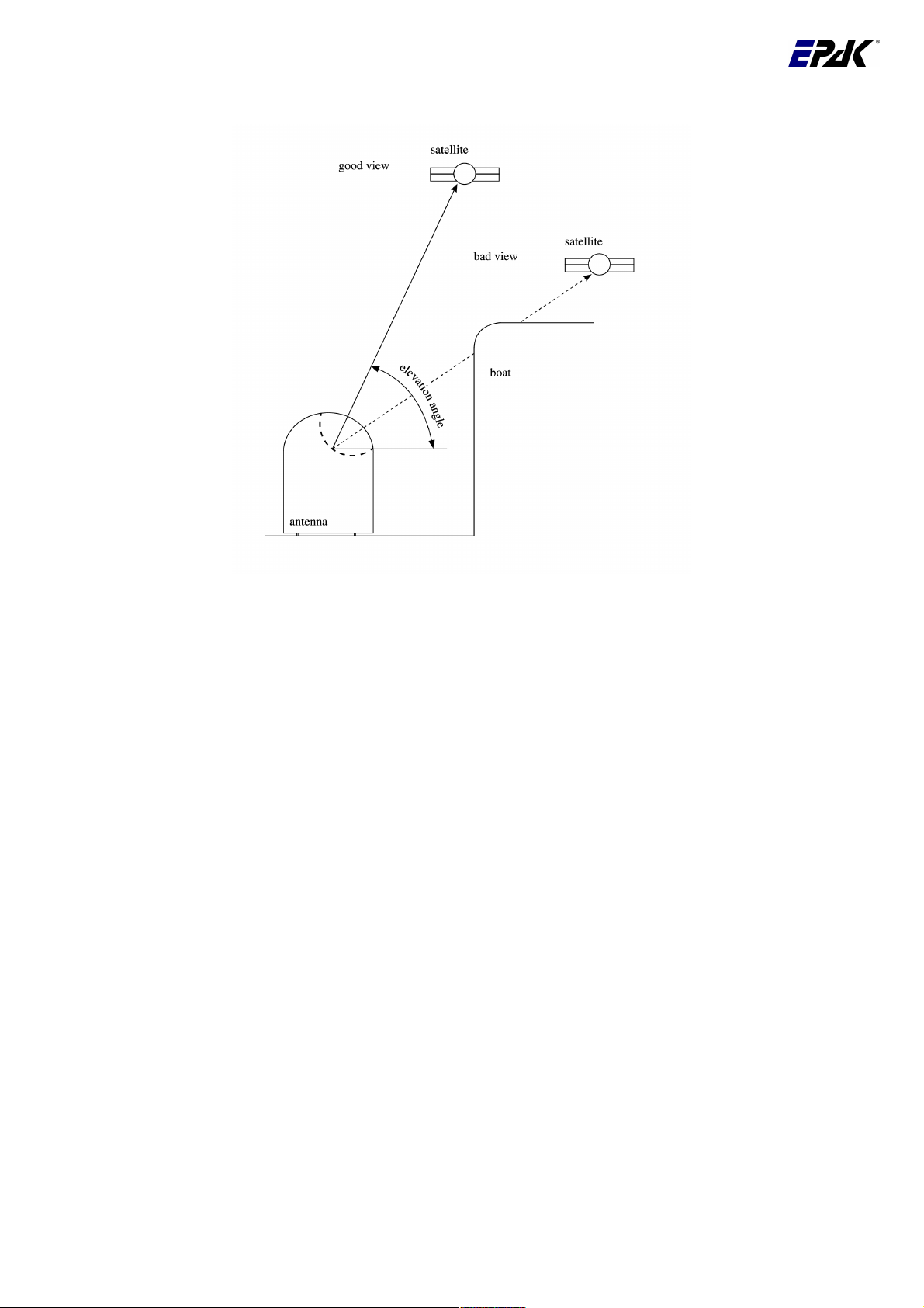
The following illustration shows the importance of a proper location for the antenna unit.
2.4. Mounting surface
A horizontal, solid and steady, and even surface has to be ensured. The weight of the antenna unit can be
26.5lbs (12kg) up to 123.6lbs (56kg) (depending on the model) and must not be confronted with punctual
material stressing. The surface has to be strong enough to carry the antenna unit, even during the most
challenging maritime conditions.
2.5. Planning the cable paths
Before starting the installation, please check which walls are suitable and if existing openings can be used
for the cables.
All openings have to be sealed!
The control unit should be placed as close as possible to the receiver. The cable length should not extend
3 m and the cable must be type 1 (see chapter 7.6.1 for data concerning appropriate cable types).
2.6. Power supply
The antenna unit can be connected directly without a converter to any ship's power supply net of 12/24/32
volts DC. The circuit fuse should be rated for min. 5 amperes and max. 7.5 amperes! (see chapter 7.8
“Technical Specifications”).
The power distributor must be idle while working on the ship's supply net or you short circuit the
system.
If the negative side of the supply voltage of the antenna unit has no connection to the boat ground, make
sure a potential compensation between boat ground and the ground point of the antenna unit is made.
English Page 7 / 34
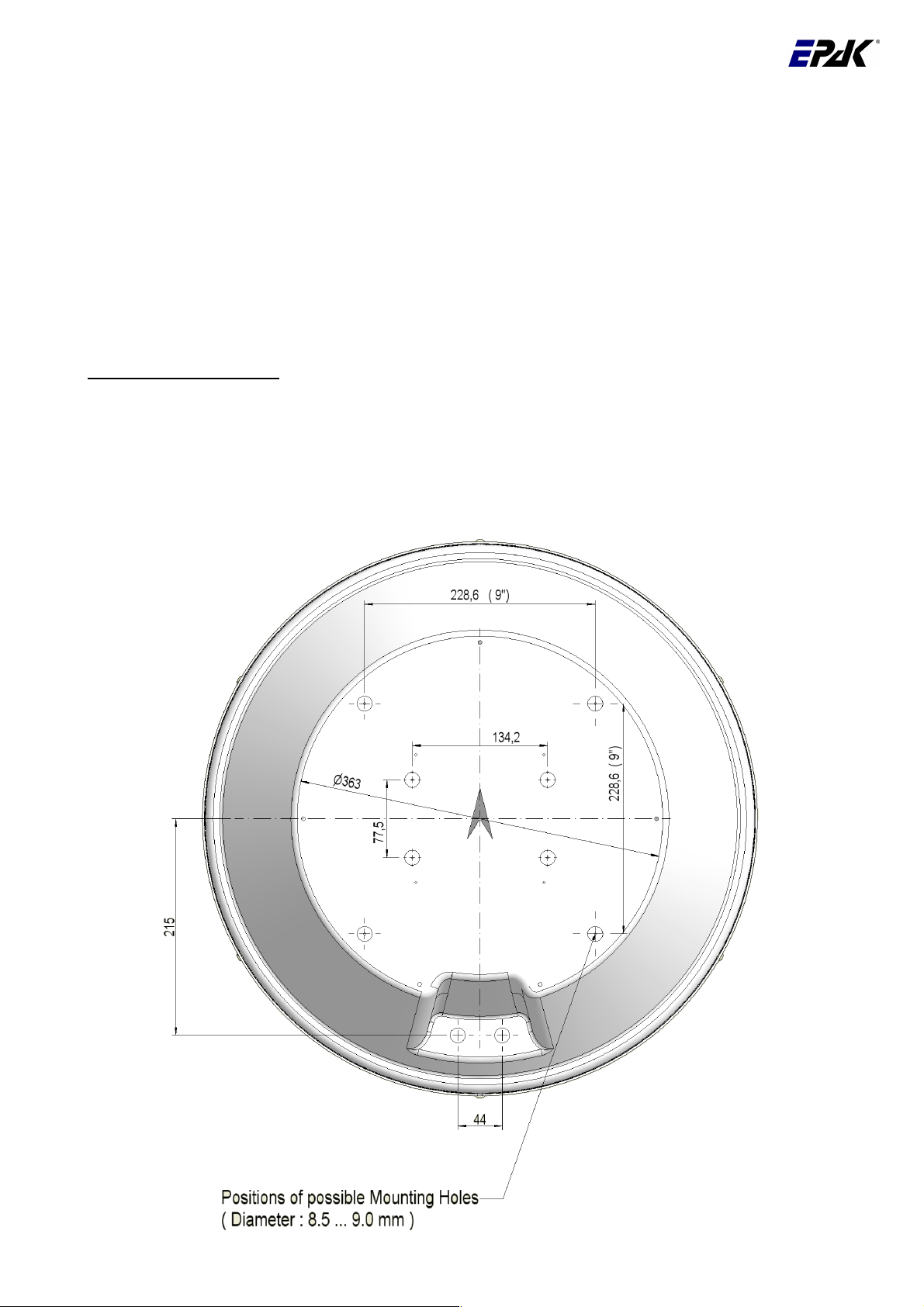
2.7. Drillings
For an ideal mounting of the antenna we prepared all possible drilling pictures with a diameter of 2 mm in
the bottom of the radome.
Please refer to the included template for the drilling measurements (see bottom from below!). The drilling
holes have to have a size of ∅ 8.5 – 9 mm for the included M8 screws. We recommend to start with
drilling a smaller hole, using a ∅ 3.5 – 4 mm bit to avoid any damage to the mounting surface. To mount
the antenna, only use the included M8 mounting screws!
!! If the antenna unit is not mounted on a device carrier or separate mounting plate, close all
drilled holes with waterproof sealing material to avoid any water penetrating!
Possible dimension s:
River Line & Basic Line: 228.6 mm x 228.6 mm and 134.2 mm x 77.5 mm
For a good and steady mounting of the antenna we recommend the drilling picture 228.6 mm x 228.6
mm. For the drilling picture 134.2 mm x 77.5 mm you will find tapped holes at the bottom plate of the
antenna, so no nuts would be necessary.
Bow
English Page 8 / 34
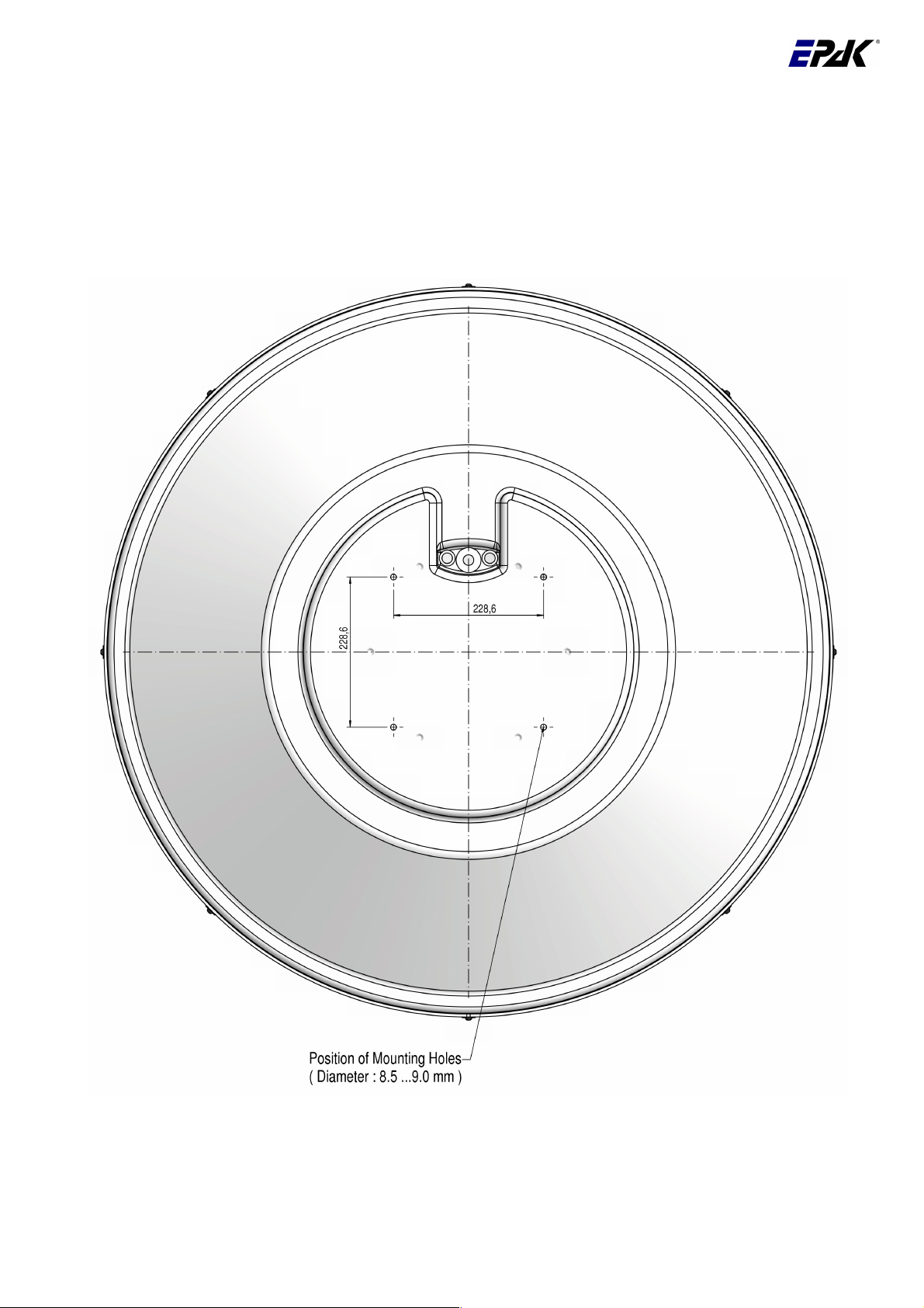
Premium Line: 228.6 mm x 228.6 mm
TV90
English Page 9 / 34
Bow

Premium Line: 228.6 mm x 228.6 mm
TV61
English Page 10 / 34
2.8. Mounting the antenna unit
The antenna unit has to be mounted on a solid and steady surface. Take care that the cable lengths are
sufficient - the antenna unit must have an unobstructed view to the satellite and that there are no
interfering fields (especially mobile communication antennas) nearby. Place the antenna unit on the predrilled holes and fasten it with the included screws and washers. The screws have to be screwed in from
below through the mounting surface into the radome.
!! Close all drilled holes with waterproof sealing material to avoid any water penetrating!
2.9. System cable connections
!! Break the contact of the circuit on which you are working to avoid a short circuit of the system.
• The antenna cable must be connected to the control unit and the antenna unit,
(cable type 1).
• The power supply cable to the power distributor and the antenna unit.
• The receiver cable to the control unit and the receiver, (cable type 1).
!! See system overview and illustration details, chapter 7.6.1 and at the end of the manual.
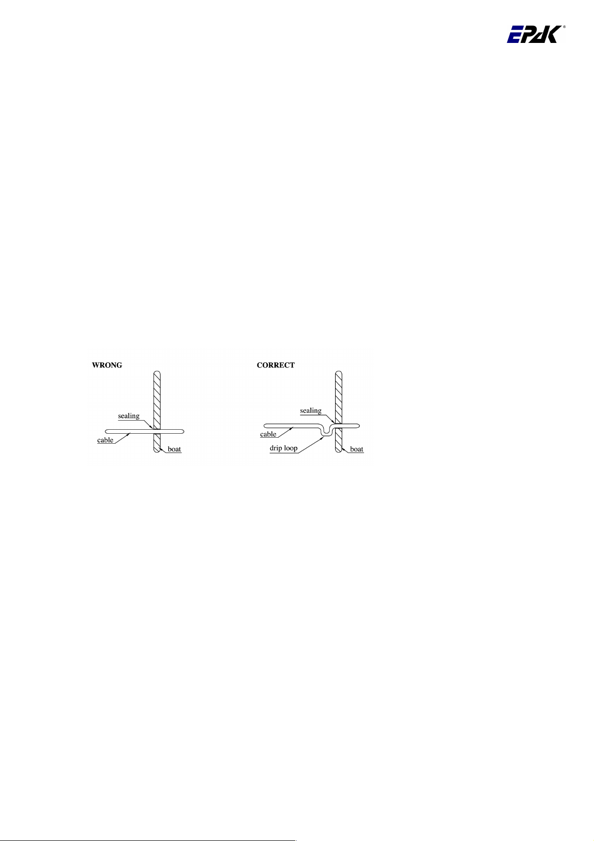
Lead the cable through the drilled holes and seal it with waterproof sealing material. Furthermore, drip
loops should precede the entry point from the exterior to avoid any water penetrating. See illustration
below:
Find a suitable location for all units within cable lengths, meaning the control unit should be placed
nearby the receiver. Take care that the display of the control unit can be easily read and the buttons are
accessible. Also, allow room for the cables behind the control unit!
The antenna unit is separated from the power supply net by the control unit. Therefore, the antenna unit
only has electric power when the control unit is turned on!
English Page 11 / 34
 Loading...