

Page 1
Protective earth monitoring for single and three phase networks
P
0
2
I
PECON+
®
For mobile use of
frequency inverters
and servo drives
The 3.5
mA-limit as per
DIN EN 50
178 / VDE 0160
may be exceeded
For networks with rated
voltages of 100
VAC
up to 480
VAC with or
without neutral
*
Instruction manual
Page 2

Page 3

PECON+
®
www.epa.de
1 of 48
Thank you for choosing the PECON+
®
protective earth monitoring system from EPA!
If you have any technical questions, please give us a call:
Phone: +49 (0) 6181 9704 - 0
For the latest information on this product, visit www.epa.de.
Page 4

PECON+®
www.epa.de
2
of
48
Contents
1 Important basic information ........................................................................................... 4
1.1 Publication details .................................................................................................. 4
1.2 Target group........................................................................................................... 5
1.3 Liability ................................................................................................................... 5
1.4 General equal treatment ......................................................................................... 5
1.5 Registered trademarks ........................................................................................... 5
1.6 Symbols and signal words ...................................................................................... 6
1.7 Marking on the product ........................................................................................... 7
1.8 CE mark ................................................................................................................. 8
1.9 EMC Limit Class ..................................................................................................... 8
1.10 Declaration of conformity ........................................................................................ 9
1.11 Product description............................................................................................... 10
1.12 Area of application ............................................................................................... 11
1.13 Delivery contents .................................................................................................. 12
2 Safety instructions ...................................................................................................... 13
2.1 Intended use ........................................................................................................ 13
2.2 Inadmissible operating conditions......................................................................... 13
2.3 Requirements for personnel ................................................................................. 14
2.4 Responsibility: ...................................................................................................... 14
2.5 Connection ........................................................................................................... 15
2.6 Follow the operating instructions .......................................................................... 16
3 Technical data ................................................................................................................ 17
3.1 Rating data PECON+
®
......................................................................................... 17
3.2 Rating data PECON+
®
S1 / S2 ............................................................................. 18
3.3 Rating data PECON+
®
S3 / S4 ............................................................................. 19
3.4 Rating data PECON+
®
NVT-1 / NVF-1 ................................................................. 20
3.5 Rating data PECON+
®
NVT-2 / NVF-2 ................................................................. 21
3.6 Rating data PECON+
®
IT ..................................................................................... 22
3.7 Dimensions .......................................................................................................... 23
4 Function ......................................................................................................................... 24
4.1 Operating principle ............................................................................................... 24
4.2 Normal state ......................................................................................................... 24
4.3 Fault ..................................................................................................................... 25
4.4 Additional functions .............................................................................................. 25
4.5 Type overview ............
.......................................................................................... 29
5 Delivery, internal transport, unpacking ........................................................................ 32
5.1 Delivery ................................................................................................................ 32
5.2 Internal transport .................................................................................................. 32
5.3 Unpacking ............................................................................................................ 32
Page 5

PECON+®
www.epa.de
3 of 48
6 Storage and transport ................................................................................................... 33
6.1 Ambient conditions ............................................................................................... 33
6.2 Storage ................................................................................................................ 33
6.3 Transport .............................................................................................................. 33
7 Installation ..................................................................................................................... 34
7.1 Safety instructions for installation ......................................................................... 34
7.2 Installation conditions ........................................................................................... 35
7.3 Operating conditions ............................................................................................ 35
7.4 Connection conditions .......................................................................................... 35
7.5 Overload protection .............................................................................................. 36
7.6 Connections ......................................................................................................... 36
7.7 Wiring diagram ..................................................................................................... 39
8 Startup / Operation ........................................................................................................ 45
8.1 Switching on ......................................................................................................... 45
8.2 Shutdown ............................................................................................................. 45
8.3 LED display elements ........................................................................................... 45
9 Troubleshooting ............................................................................................................ 46
9.1 All LEDs remain dark ............................................................................................ 46
9.2 Red LED is illuminated ......................................................................................... 46
9.3 Service address ................................................................................................... 46
10 System inspection and maintenance ........................................................................... 47
11 Repairs ........................................................................................................................... 48
12 Disposal ......................................................................................................................... 48
Page 6

Important basic information
PECON+®
www.epa.de
4 of 48
1 Important basic information
1.1 Publication details
Published by:
EPA GmbH
Fliederstr. 8
63486 Bruchköbel
Germany
Phone: +49 (0) 6181 - 9704- 0
Fax: +49 (0) 6181 - 9704- 99
E-mail: [email protected]
Web: www.epa.de
Author:
T. Bozem
Photos:
A. Mayer
Implementation:
K. Bonkosch
Issue number:
1.6 / 11/2018
Validity of device version:
PECON+®
PECON+® S1 / S2 / S3 / S4
PECON+® NVT-1 / -2
PECON+® NVF-1 / -2
PECON+® IT
© EPA GmbH
All rights, including the rights to photomechanical reproduction and storage in electronic
media, are reserved by EPA GmbH. Commercial use or distribution of the text, models,
drawings and photos used in this product is not permitted. No part of this publication may
be reproduced, stored or transferred, distributed or translated in any form or using any
medium without prior written permission.
Page 7

Important basic information
PECON+®
www.epa.de
5
of
48
1.2 Target group
This documentation is intended for qualified personnel as defined in IEC 60364.
Qualified personnel are persons who have the appropriate qualifications for the work to be
performed during the installation, assembly, startup and operation of the product.
1.3 Liability
The common names, trade names, descriptions of goods and other designations used in
this publication may be legally protected even if not specifically marked as such (for
example as trademarks). EPA GmbH accepts no liability or warranty for their free
availability.
The illustrations and text were compiled with the utmost care. Nevertheless, errors cannot
be excluded.
The publication is provided without guarantee.
The information it contains is provided solely for the purpose of customer information and
contains no representations or binding warranties. Binding statements are possible only in
response to specific inquiries.
The contents of this instruction manual are accurate at the date of printing. Because it is
under continuous development, the manufacturer reserves the right to change the
specification of the product and its performance data as well as the contents of this
instruction manual, in both technical and commercial terms, without prior notice. The
current version is available at www.epa.de.
Liability of the company EPA GmbH for any damage resulting from incorrect use of this
instruction manual or incorrect, erroneous or inappropriate installation or adjustment is
excluded. Interruptions to operation, loss of profit as well as loss of information and data or
consequential damages are excluded insofar as liability is not mandatory in accordance
with the law on product liability or in cases of intent, gross negligence or breach of
fundamental contractual obligations.
1.4 General equal treatment
EPA GmbH is aware of the importance of language with respect to the equal rights of
women and men and makes every effort to take this into account. To ensure better
readability, however, it was necessary to abstain from the consistent use of differentiated
formulations.
1.5 Registered trademarks
Brand names and trademarks are the property of their respective owners and are not
generally marked as such in this manual.
The absence of such marking does not mean that a name is free within the meaning of
brand and trademark law.
Page 8
Important basic information
PECON+®
www.epa.de
6
of
48
1.6 Symbols and signal words
The following symbols and signal words are used in this documentation to indicate hazards
and important information:
Symbol/signal word
Meaning
Warning of hazardous electrical voltage
DANGER
Draws your attention to a hazardous situation that will
result in serious injury or death if not avoided.
WARNING
Draws your attention to a hazardous situation that may
result in serious injury or death if not avoided.
CAUTION
Draws your attention to a hazardous situation that may
result in minor to moderate injury if not avoided.
IMPORTANT NOTE
Draws your attention to the handling and impact of safety
information.
NOTE
Draws your attention to the handling and impact of safety
information.
Draws your attention to possible damage to property and
other important information.
The installation must be carried out by a qualified
electrician (IEC 60417-6182).
Page 9
Important basic information
PECON+®
www.epa.de
7 of 48
1.7 Marking on the product
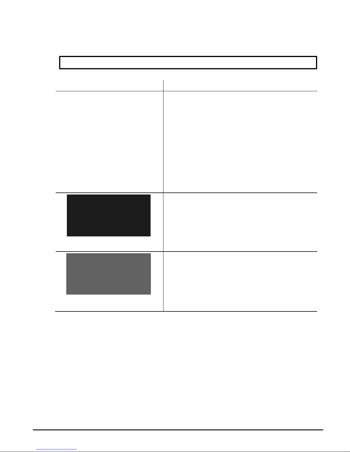
The marking on the device may vary depending on the product version.
Illustration Description
Fig. 1: Example: PECON+®
Front panel
LED status displays
Labelling of terminals
Test key
Fig. 2: Example: PECON+®
Type plate
Technical data and manufacturer
information
Fig. 3: Example: PECON+®
Terminal assignment
Product-specific terminal assignment
Page 10
Important basic information
PECON+®
www.epa.de
8 of 48
1.8 CE mark
The CE mark is on the device nameplate.
The device complies with the relevant essential requirements of all applicable EU
directives. The declaration of conformity can be found in the section "Declaration of
conformity" or downloaded from www.epa.de.
1.9 EMC Limit Class
The device complies with the limits for emitted interference according to DIN EN 55011
class B group 1.
The device's interference immunity corresponds to DIN EN 61000-6-2 for the industrial
environment.
The device is classified in accordance with DIN EN 61326-1 (VDE 0843-20-1) and is
suitable for use in residential, business and commercial areas as well as in industrial
environments.
Page 11

Important basic information
PECON+®
www.epa.de
9 of 48
1.10 Declaration of Conformity
Page 12

Important basic information
PECON+®
www.epa.de
10 of 48
1.11 Product description
A familiar problem for manufacturers of machinery and pluggable devices:
Due to modern drive regulators such as frequency converters or servo controllers, the
operational leakage current of the device or machine may increase.
However, DIN EN 50178/VDE 0160 only permits an operational leakage current of up to 3.5
mA AC. If this value is exceeded, the standard stipulates that the protective earth requires a
fixed connection. This limits the mobility of the machines or devices.
However, this leakage current can be minimised through the careful arrangement of the
individual components as well as with complex network filters. Unfortunately, this
implementation is usually too expensive, and in many cases the operational leakage current
is still above 3.5 mA due to the system.
The notion of the standard is reasonable and understandable as it protects the users of the
machines or devices from electric shock if such a device is disconnected from the
protective earth system due to a defective connection cable, plug or extension cable. But in
addition, the standard expressly allows higher leakage currents if the availability of the
protective earth system is permanently monitored. This is where the PECON+
®
comes in.
The PECON+
®
is a monitoring device that is installed directly at the feed point of the mobile
machine.
The quality of the protective earth is permanently monitored by the PECON+
®
. If it is
working flawlessly, the integrated signal contact of the PECON+
®
releases the main
contactor of the machine.
The device, which is only 45 mm wide, is mounted on a DIN rail and reliably monitors all
common voltage ranges.
The PECON+
®
is used for monitoring the protective earth of single phase and 3-phase
pluggable consumers. Depending on the product, polarity reversal of phase (L) and neutral
conductor (N) is also monitored. Other product variants with special functions are also
available.
The PECON+
®
IT is available for networks without neutral conductor (N).
Page 13

Important basic information
PECON+®
www.epa.de
11
of
48
1.12 Area of application
Leakage current >3.5 mA = danger to life!?
Manufacturers and operators of machinery as well as portable or mobile electrical devices
are equally affected. If an electrical device continuously exceeds a leakage current of AC
3.5 mA (in some regulations the limit is set to AC 10 mA) during normal use, it is subject to
special regulations.
Why this strict limit?
When a residual current circuit breaker (RCCB) is used, you can rest assured that the
personnel is adequately protected. Or are they?
Of course not every instance of touching electricity leads to injury or even death. If a live
object is merely touched, the person generally removes the affected body part from the
danger by virtue of the natural muscle reflex.
A more critical danger presents itself when we clasp a live machine part. Door handles,
control levers, climbing aids etc. present typical risks. Internationally recognised standards
already define body currents of only 15 mA as a "release limit", meaning that the muscles of
the energised body part cramp and render the victim unable to release their grip.
All is well for the residual current circuit breaker!
Innovative machine concepts and electromobility often cannot be realised without inverters,
frequency converters, servo drives or intelligent charging concepts.
In most instances, mains filters with Y capacitors (C between outer conductor and PE) are
used for EMC reasons. However, two small Y-suppressor capacitors of only 100 nF can
already cause leakage currents well above the 10 mA limit.
This is where VDE, TÜV and BG come in:
Producing leakage currents for trouble-free operation is generally permitted. However,
developers are obliged to ensure that the electrical equipment is equipped with suitable
protective earthing. Only then can the risk of a dangerous potential increase of touchable,
conductive parts of the machine be safely ruled out.
In general, the relevant standards (e.g. DIN EN 50178) equally permit the following
solutions for leakage currents AC > 3.5 mA:
- Installation of a second protective earth
- Installation of a separate isolating transformer
- Automatic disconnection of the power supply if the protective earth is interrupted
Page 14
Important basic information
PECON+®
www.epa.de
12 of 48
1.13 Delivery contents
Protective earth monitoring
PECON+
®
Instruction manual
PECON+
®
Page 15
Safety instructions
PECON+®
www.epa.de
13 of 48
2 Safety instructions
2.1 Intended use
The EPA PECON+
®
is used to safely monitor and automatically disconnect the power
supply in the event of interruption of the protective earth (PE) in single and 3-phase
networks in accordance with standard DIN EN 50178 / VDE 0160:1998-04.
The PECON+
®
determines the availability of the protective earth of consumers (usually
pluggable connected) by measurement and actuates an internal release relay if the
protective earth is present.
The monitoring device must be installed directly on the feed point of the machine/system.
Depending on the product, the polarity reversal of phase (L) and neutral conductor (N) is
also monitored and reported. Other product variants with special functions are available,
e.g. for switching phases and the neutral conductor after release (for all PECON+
®
NV
variants).
The PECON+
®
IT is available for networks without neutral conductor.
NOTE
Particular attention should be paid to the safety instructions and the technical data
setting out the ambient conditions.
2.2 Inadmissible operating conditions
CAUTION
The PECON+
®
must only be used under the conditions and for the purposes for which
it was designed (see section "Intended use").
Operational safety is not guaranteed in the event of modification or improper use.
The device is not suitable for reducing leakage currents.*
The PECON+
®
does not replace a residual current device.
High voltage differences between the neutral conductor and the protective earth
conductor can overload or destroy the device.
Strong electromagnetic fields can affect the function of the device.
External mechanical loads are not allowed.
Use in potentially explosive atmospheres is prohibited.
*
EPA GmbH offers various other products for this purpose.
Page 16
Safety instructions
PECON+®
www.epa.de
14 of 48
2.3 Requirements for personnel
WARNING
Installation and work on the PECON+
®
1C may only be carried out by
qualified personnel.
Qualified personnel as defined by this instruction manual are
electricians who are familiar with the installation, assembly, startup and operation of
the device, with the hazards involved, and who, based on their technical training, are
also familiar with the relevant standards and provisions.
Repairs may only be carried out by authorised repair centres. Unauthorised tampering
can lead to property damage and will void the warranty provided by EPA GmbH.
2.4 Responsibility:
WARNING
Electronic devices are never fail-safe. The installer and/or operator of the machine or
system is responsible for ensuring that the system/machine is restored to a safe state
if the device fails.
The safety requirements for electrical controllers are set out in DIN EN 60204-1; VDE
0113-1 "Safety of machinery" in the section titled "Electrical equipment of machines".
These provisions ensure the safety of persons and machines as well as the
maintenance of the functional capability of the machine or system and must be
observed.
Page 17
Safety instructions
PECON+®
www.epa.de
15 of 48
2.5 Connection
WARNING of hazardous electrical voltage
Risk to life from electric shocks! Death or serious injury!
To avoid electric shock, take appropriate precautions.
Follow the accident prevention regulations for electrical systems and equipment when
carrying out all work.
WARNING
The terminals are intended solely for the purpose for which they are defined in the
connection description. These must not be used for any other purpose.
The potential at the terminals can be at the mains voltage level under certain
circumstances. For safety reasons, the connecting cables must therefore have a
corresponding dielectric strength and be sufficiently insulated.
CAUTION
The device must be supplied with the voltage specified in the technical data. Higher
voltages can destroy the device.
Surge voltages between the terminals can destroy the device.
The device must be fixed firmly into place while the power supply is disconnected
and no parts are live.
A fixed, low-impedance connection is required between the PE connection and the
protective earth.
The PECON+
®
may only be operated in TN-S systems (separate neutral and protective
earth throughout the system; grounded star point).
Page 18

Safety instructions
PECON+®
www.epa.de
16 of 48
2.6 Follow the operating instructions
IMPORTANT NOTE
Please read this manual carefully. It contains important information about the
installation and operation of the PECON+
®
.
The PECON+
®
has been subjected to extensive testing and left the factory in a
technically and operationally safe condition. To maintain this condition, the user must
follow the safety instructions in this manual.
We assume no liability for damage caused by failure to follow these instructions.
This manual is an integral part of the product and is valid only for the
PECON+
®
protective earth monitoring device manufactured by EPA GmbH.
Please pass this manual on to the system operator / end customer / service technician
so that it is available when required.
Keep these operating instructions and all other applicable documents in a safe place to
ensure that they are available when required.
This is a translation of the original German instruction manual.
The current edition of this operating manual can be downloaded from www.epa.de.
Page 19

Technical data
PECON+®
www.epa.de
17 of 48
3 Technical data
3.1 Rating data PECON+®
Testable networks
Single phase: L / N / PE
3-phase with N: L1 / L2 / L3 / N / PE
Network configuration
TN-S system
Rated voltage
200..230 VAC (±10%)
Rated frequency
50 / 60 Hz (±5%)
Response lag
<0.4 s
Response threshold
<1000 Ω
Power loss
5 VA
Ambient temperature
Operation: -15...+40ºC
Storage: -25...+70ºC
Transport: -25...+70ºC
Rel. humidity
max. 98%, without condensation
Atmospheric pressure
70..106ºC,
Dimensions
75 x 45 x 125 mm
Weight
Approx. 400 g
Mounting / fitting
on TS35 mounting rail according to DIN EN 50022, installation
position as required
Connections
Mains connection: L / N
Protective earth terminal: PE
Release relay: Alarm/operation (change-over
contact)
Other connections: External Test key (break contact)
Contact rating
max. 250 VAC / 5 A; 30 VDC / 2 A
Cable cross-section
max. 4.0 mm² (12 AWG) solid
max. 2.5 mm² (14 AWG) flexible with sleeve
Tightening torque
max. 0.8 Nm
LED displays
green: OK (operating mode display)
yellow: Phase an N (polarity reversal L / N)
red: Alarm (PE interruption)
_
Function test
via test key on front cover or ext. test key
Protection class
IP20 (terminals), IP40 (housing)
Direct contact protection
DGUV V3 (BGV A3)
Flammability
UL94 V-0
Housing material
PC-GF
Normative basis
DIN EN 50178 / VDE 0160:1998-04
Safety
DIN EN 61010-1, DIN EN 60204-1
EMC
DIN EN 61326-1, DIN EN 55011
Conformity
CE, RoHS (2011/65/EU),
LVD (2006/95/EG), EMCD (2004/108/EG), MD (2006/42/EG)
Page 20

Technical data
PECON+®
www.epa.de
18 of 48
3.2 Rating data PECON+® S1 / S2
Testable networks
Single phase: L / N / PE
3-phase with N: L1 / L2 / L3 / N / PE
Network configuration
TN-S system
Rated voltage
200..230 VAC (±10%)
Rated frequency
50 / 60 Hz (±5%)
Response lag
<0.4 s
Response threshold
<1000 Ω
Power loss
5 VA
Ambient temperature
Operation: -15...+40ºC
Storage: -25...+70ºC
Transport: -25...+70ºC
Rel. humidity
max. 98%, without condensation
Atmospheric pressure
70..106 kPa
Dimensions
75 x 45 x 125 mm
Weight
Approx. 400 g
Mounting / fitting
on TS35 mounting rail according to DIN EN 50022, installation
position as required
Connections
Mains connection:
L / N
Protective earth terminal: PE
Release relay:
Alarm/operation (change-over
contact)
Other connections:
Polarity reversal L / N (normally
open)
Contact rating
max. 250 VAC / 5 A; 30 VDC / 2 A
Cable cross-section
max. 4.0 mm² (12 AWG) solid
max. 2.5 mm² (14 AWG) flexible with sleeve
Tightening torque
max. 0.8 Nm
LED displays
green: OK (operating mode display)
yellow: Phase an N (polarity reversal L / N)
red: Alarm (PE interruption)
_
Function test
via test key on front cover
Protection class
IP20 (terminals), IP40 (housing)
Direct contact protection
DGUV V3 (BGV A3)
Flammability
UL94 V-0
Housing material
PC-GF
Normative basis
DIN EN 50178 / VDE 0160:1998-04
Safety
DIN EN 61010-1, DIN EN 60204-1
EMC
DIN EN 61326-1, DIN EN 55011
Conformity
CE, RoHS (2011/65/EU),
LVD (2006/95/EG), EMCD (2004/108/EG), MD (2006/42/EG)
Page 21

Technical data
PECON+®
www.epa.de
19 of 48
3.3 Rating data PECON+® S3 / S4
Testable networks
Single phase: L / N / PE
3-phase with N: L1 / L2 / L3 / N / PE
Network configuration
TN-S system
Rated voltage
100..125 VAC (±10%)
Rated frequency
50 / 60 Hz (±5%)
Response lag
<0.4 s
Response threshold
<1000 Ω
Power loss
<5 VA
Ambient temperature
Operation: -15...+40ºC
Storage: -25...+70ºC
Transport: -25...+70ºC
Rel. humidity
max. 98%, without condensation
Atmospheric pressure
70..106 kPa
Dimensions
75 x 45 x 125 mm
Weight
Approx. 400 g
Mounting / fitting
on TS35 mounting rail according to DIN EN 50022, installation
position as required
Connections
Mains connection: L / N
Protective earth terminal: PE
Release relay: Alarm/operation (change-over
contact)
Other connections: Polarity reversal L / N (normally
open)
Contact rating
max. 250 VAC / 5 A; 30 VDC / 2 A
Cable cross-section
max. 4.0 mm² (12 AWG) solid
max. 2.5 mm² (14 AWG) flexible with sleeve
Tightening torque
max. 0.8 Nm
LED displays
green: OK (operating mode display)
yellow: Phase an N (polarity reversal L / N)
red: Alarm (PE interruption)
_
Function test
via test key on front cover
Protection class
IP20 (terminals), IP40 (housing)
Direct contact protection
DGUV V3 (BGV A3)
Flammability
UL94 V-0
Housing material
PC-GF
Normative basis
DIN EN 50178 / VDE 0160:1998-04
Safety
DIN EN 61010-1, DIN EN 60204-1
EMC
DIN EN 61326-1, DIN EN 55011
Conformity
CE, RoHS (2011/65/EU),
LVD (2006/95/EG), EMCD (2004/108/EG), MD (2006/42/EG)
Page 22

Technical data
PECON+®
www.epa.de
20 of 48
3.4 Rating data PECON+® NVT-1 / NVF-1
Testable networks
Single phase: L / N / PE
3-phase with N: L1 / L2 / L3 / N / PE
Network configuration
TN-S system
Rated voltage
200..230 VAC (±10%)
Rated frequency
50 / 60 Hz (±5%)
Response lag
<0.4 s
Response threshold
<1000 Ω
Power loss
5 VA
Ambient temperature
Operation: -15...+40ºC
Storage: -25...+70ºC
Transport: -25...+70ºC
Rel. humidity
max. 98%, without condensation
Atmospheric pressure
70..106 kPa
Dimensions
75 x 45 x 125 mm
Weight
Approx. 400 g
Mounting / fitting
on TS35 mounting rail according to DIN EN 50022, installation
position as required
Connections
Mains connection: L / N
Protective earth terminal: PE
Release relay 1: Alarm/operation (change-over
contact)
Release relay 2: Operation (NO contact)
Other connections: External Test key (break contact)
_
Contact rating
max. 250 VAC / 16 A
Cable cross-section
max. 4.0 mm² (12 AWG) solid
max. 2.5 mm² (14 AWG) flexible with sleeve
Tightening torque
0.8 Nm
LED displays
green: OK (operating mode display)
yellow: Phase an N (polarity reversal L / N)
red: Alarm (PE interruption)
Function test
via test key on front cover or ext. test key
Protection class
IP20 (terminals), IP40 (housing)
Direct contact protection
DGUV V3 (BGV A3)
Flammability
UL94 V-0
Housing material
PC-GF
Normative basis
DIN EN 50178 / VDE 0160:1998-04
Safety
DIN EN 61010-1, DIN EN 60204-1
EMC
DIN EN 61326-1, DIN EN 55011
Conformity
CE, RoHS (2011/65/EU),
LVD (2006/95/EG), EMCD (2004/108/EG), MD (2006/42/EG)
Page 23

Technical data
PECON+®
www.epa.de
21 of 48
3.5 Rating data PECON+® NVT-2 / NVF-2
Testable networks
Single phase: L / N / PE
3-phase with N: L1 / L2 / L3 / N / PE
Network configuration
TN-S system
Rated voltage
200..230 VAC (±10%)
Rated frequency
50 / 60 Hz (±5%)
Response lag
<0.4 s
Response threshold
<1000 Ω
Power loss
5 VA
Ambient temperature
Operation: -15...+40ºC
Storage: -25...+70ºC
Transport: -25...+70ºC
Rel. humidity
max. 98%, without condensation
Atmospheric pressure
70..106 kPa
Dimensions
75 x 45 x 125 mm
Weight
Approx. 400 g
Mounting / fitting
on TS35 mounting rail according to DIN EN 50022, installation
position as required
Connections
Mains connection: L / N
Protective earth terminal: PE
Release relay 1: Alarm/operation (change-over
contact)
Release relay 2: Operation (NO contact)
Other connections: Polarity reversal L / N (normally
open)
_
Contact rating
Release relay 1 + 2: max. 250 VAC / 16 A
Signal contact: max. 60 VDC / 1 A
Cable cross-section
max. 4.0 mm² (12 AWG) solid
max. 2.5 mm² (14 AWG) flexible with sleeve
Tightening torque
0.8 Nm
LED displays
green: OK (operating mode display)
yellow: Phase an N (polarity reversal L / N)
red: Alarm (PE interruption)
Function test
via test key on front cover
Protection class
IP20 (terminals), IP40 (housing)
Direct contact protection
DGUV V3 (BGV A3)
Flammability
UL94 V-0
Housing material
PC-GF
Normative basis
DIN EN 50178 / VDE 0160:1998-04
Safety
DIN EN 61010-1, DIN EN 60204-1
EMC
DIN EN 61326-1, DIN EN 55011
Conformity
CE, RoHS (2011/65/EU),
LVD (2006/95/EG), EMCD (2004/108/EG), MD (2006/42/EG)
Page 24

Technical data
PECON+®
www.epa.de
22 of 48
3.6 Rating data PECON+® IT
Testable networks
3-phase without N: L1/ L2/ L3 / PE
Network configuration
TN-S system
Rated voltage
380..480 VAC (±10%)
Rated frequency
50 / 60 Hz (±5%)
Response lag
<0.4 s
Response threshold
<1000 Ω
Power loss
<23 VA
Ambient temperature
Operation: -15...+40ºC
Storage: -25...+70ºC
Transport: -25...+70ºC
Rel. humidity
max. 98%, without condensation
Atmospheric pressure
70..106 kPa
Dimensions
75 x 45 x 125 mm
Weight
Approx. 500 g
Mounting / fitting
on TS35 mounting rail according to DIN EN 50022, installation
position as required
Connections
Mains connection:
L / N
Protective earth terminal: PE
Release relay:
Alarm/operation (change-over
contact)
Other connections:
External Test key (break contact)
Contact rating
max. 250 VAC / 5 A; 30 VDC / 2 A
Cable cross-section
max. 4.0 mm² (12 AWG) solid
max. 2.5 mm² (14 AWG) flexible with sleeve
Tightening torque
0.8 Nm
LED displays
green: OK (operating mode display)
yellow: Mains phase fault (high voltage difference)
red: Alarm (PE interruption)
_
Function test
via test key on front cover or ext. test key
Protection class
IP20 (terminals), IP40 (housing)
Direct contact protection
DGUV V3 (BGV A3)
Flammability
UL94 V-0
Housing material
PC-GF
Normative basis
DIN EN 50178 / VDE 0160:1998-04
Safety
DIN EN 61010-1, DIN EN 60204-1
EMC
DIN EN 61326-1, DIN EN 55011
Conformity
CE, RoHS (2011/65/EU),
LVD (2006/95/EG), EMCD (2004/108/EG), MD (2006/42/EG)
Page 25
Technical data
PECON+®
www.epa.de
23 of 48
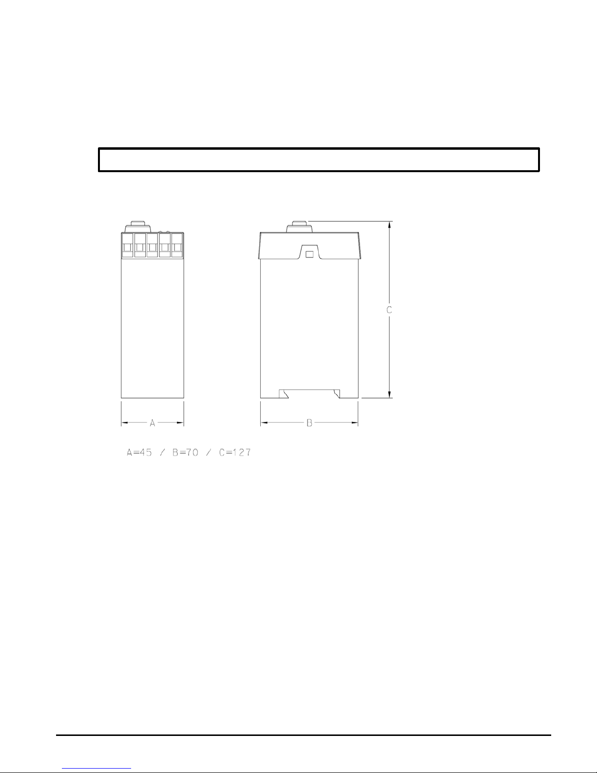
3.7 Dimensions
All dimensions are specified in mm. Tolerance ±1 mm. Subject to change.
3D and CAD files can be downloaded at www.epa.de.
DIN rail EN 50 022
Page 26

Function
PECON+®
www.epa.de
24
of
48
4
Function
4.1 Operating principle
The PECON+
®
determines the availability of the protective earth of single and 3-phase networks by
measurement.
If the protective earth is available, an internal release relay (potential-free contacts) is actuated. A
separate line contactor can now be switched via the signal contact in order to supply the
consumer(s) with voltage.
4.2 Normal state
When the PECON+
®
is ready for operation, the green LED "OK" on the front cover is illuminated and
the "Betrieb" (“Operation”) signal contact is activated.
For the PECON+
®
NVT and PECON+® NVF models, two internal release relays are activated
(signal contacts “Freigabe-Relais 1” ("Release relay 1") and “Freigabe-Relais 2” ("Release
relay 2").
Contact position release relay in working position è Protective earth OK
Page 27

Function
PECON+®
www.epa.de
25 of 48
4.3 Fault
When the protective earth is interrupted, the release relay in the PECON+
®
trips immediately.
The fault is signalled by the red "Alarm" LED in the front cover, and the "Alarm" signal contact is
actuated.
Contact position release relay in idle position è Protective interrupted (alarm)
4.4 Additional functions
Interchanging of L and N
The yellow LED “Phase an N” ("Phase to N") lights up if terminal L is connected to neutral and
terminal N is connected to a phase.
A typical case: The plug was inserted the wrong way in a Schuko socket.
This function does not apply for PECON+® IT.
Continued on next page
Page 28

Function
PECON+®
www.epa.de
26
of
48
Continued
Depending on the model, swapping the phase and neutral can be interpreted as a fault or deemed
acceptable for release.
An additional signal contact for "Reverse polarity L / N" is provided for models PECON+
®
S1 /
S2 / S3 / S4 and PECON+
®
NVT-2 / NVF-2.
The differences between the various models are explained below:
PECON+
®
• The device is ready for operation despite polarity reversal (polarity reversal L / N is tolerated)
PECON+
®
S1 and PECON+® S3:
• The device is not ready for operation if the polarity is reversed (interpreted as fault).
• An additional signal contact is actuated if the polarity is reversed.
• The connection option “Ext. Prüftaste” (“Ext. test key”) cannot be used.
PECON+
®
S2 and PECON+® S4:
• The device is ready for operation despite polarity reversal (polarity reversal L / N is tolerated)
• An additional signal contact is actuated if the polarity is reversed.
• The connection option “Ext. Prüftaste“ (“Ext. test key”) cannot be used.
PECON+
®
NVT-1:
• The device is ready for operation despite polarity reversal (polarity reversal L / N is tolerated)
PECON+
®
NVF-1:
• The device is not ready for operation if the polarity is reversed (interpreted as fault).
PECON+
®
NVT-2:
• The device is ready for operation despite polarity reversal (polarity reversal L / N is tolerated)
• An additional signal contact is actuated if the polarity is reversed.
• The connection option “Ext. Prüftaste” (“Ext. test key”) cannot be used.
PECON+
®
NVF-2:
• The device is not ready for operation if the polarity is reversed (interpreted as fault).
• An additional signal contact is actuated if the polarity is reversed.
• The connection option “Ext. Prüftaste” (“Ext. test key”) cannot be used.
Continued on next page
Page 29
Function
PECON+®
www.epa.de
27
of
48
Continued
Network phases fault
This function only applies to the PECON+
®
IT.
All three mains phases must be connected to the device. A neutral connection is not
provided/required. The connection terminals for phases L1, L2 and L3 can be assigned in any phase
relation. The phase relation does not impact the functionality of the PECON+
®
IT.
If a voltage difference between the three phases L1, L2 and L3 of well above 10% is present, the
yellow LED “Fehler Netzphasen” ("Fault mains phase") lights up. The red LED "Alarm" also lights up
and there is no release via the internal relay.
Reset function
CAUTION
The PECON+
®
resets automatically!
If the protective earth is interrupted for a short period and then present again, it is automatically reenabled.
The hysteresis of the response and fallback values prevents possible fluttering of the release relay.
Function test with test key
Proper function of the “Schutzleiterunterbrechung” ("Protective earth interruption") can be checked
manually at any time using the test key on the front cover.
Continued on next page
Page 30

Function
PECON+®
www.epa.de
28 of 48
Continued
Function test with ext. test key
If needed, an external test key can be connected to the “Ext. Prüftaste” ("Ext. test key") terminal in
place of the factory-fitted jumper. The button must be implemented as a normally open contact.
Functional testing with external test key is possible with the following product variants:
PECON+
®
PECON+
®
IT
PECON+
®
NVT-1
PECON+
®
NVF-1
Functional testing with external test key is not possible with the following product variants:
PECON+
®
S1
PECON+
®
S2
PECON+
®
S3
PECON+
®
S4
PECON+
®
NVT-2
PECON+
®
NVF-2
Page 31
Function
PECON+®
www.epa.de
29 of 48
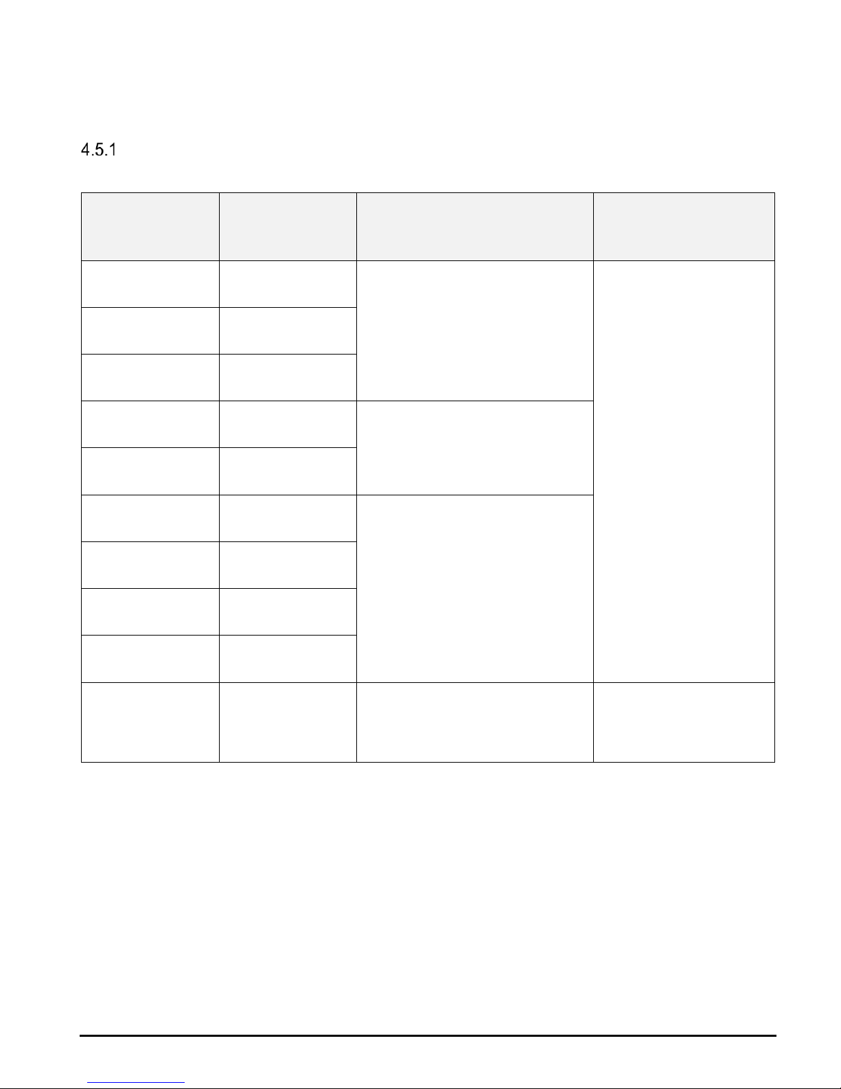
4.5 Type overview
Operating voltage / neutral connection
Device version EPA article no. Operating voltage
Neutral conductor
mandatory
PECON+® 50275390
200-230 VAC
+/-10%
50/60 Hz
yes
PECON+® S1 50275459
PECON+® S2 50275460
PECON+® S3 50275461
100-125 VAC
+/-10%
50/60 Hz
PECON+® S4 50275462
PECON+® NVT-1 50275694
200-230 VAC
+/-10%
50/60 Hz
PECON+® NVF-1 50275695
PECON+® NVT-2 50275696
PECON+® NVF-2 50275697
PECON+® IT 50275391
380-480 VAC
+/-10%
50/60 Hz
no
Page 32

Function
PECON+®
www.epa.de
30 of 48
Optional terminals
Device version
Terminal for external
test button
Terminal for reverse
polarity L / N
2
nd
release relay
PECON+® yes no
no
PECON+® S1
no yes
PECON+® S2
PECON+® S3
PECON+® S4
PECON+® NVT-1
yes no yes
PECON+® NVF-1
PECON+® NVT-2
no yes yes
PECON+® NVF-2
PECON+® IT yes no no
Page 33
Function
PECON+®
www.epa.de
31 of 48
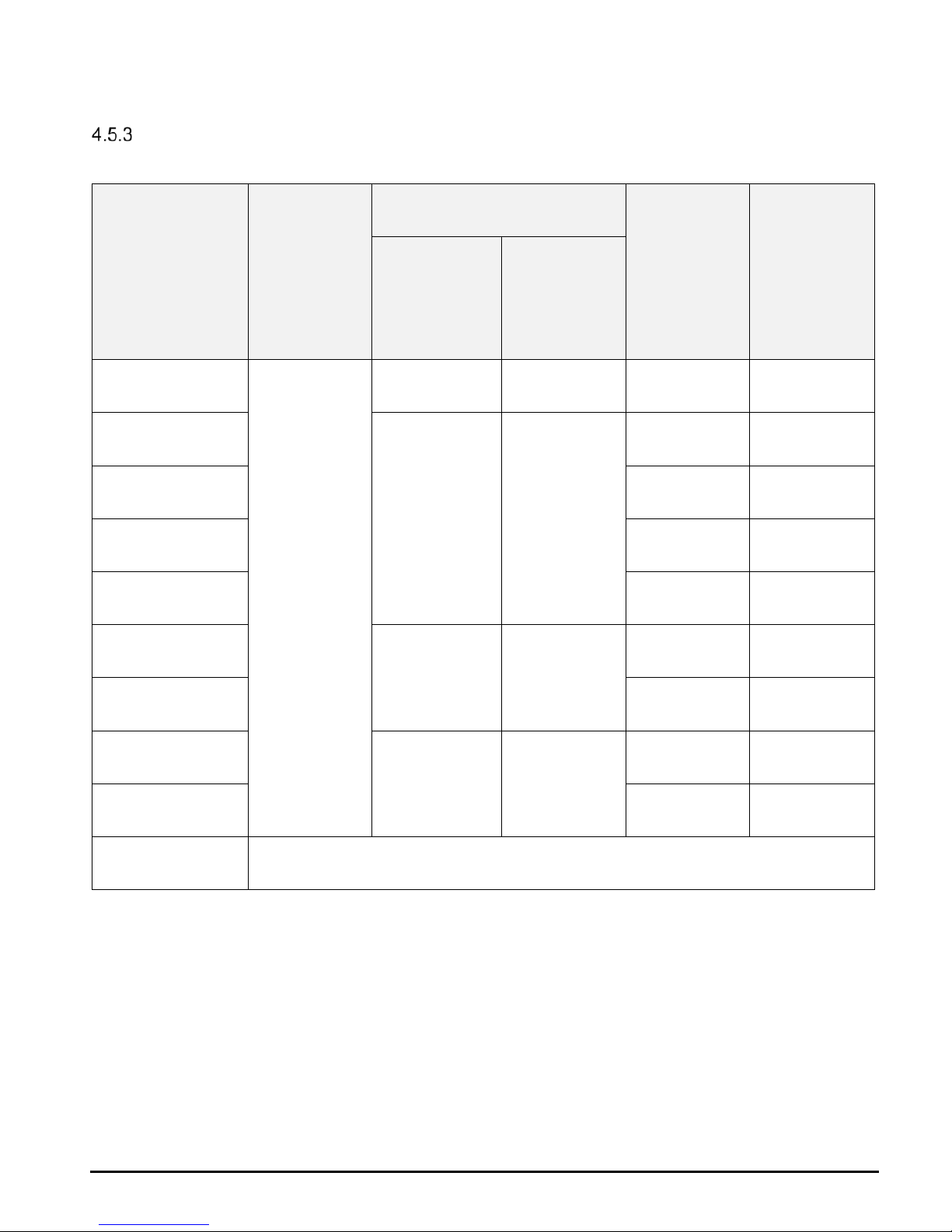
Additional function reverse polarity L / N
Device version
yellow LED
lights up if
polarity is
reversed
additional signal contact red LED
(alarm)
lights up if
polarity is
reversed
Release
relay is
energised
despite
reversed
polarity
present switches in
case of
reversed
polarity
PECON+®
yes
no no no yes
PECON+® S1
yes yes
yes no
PECON+® S2 no yes
PECON+® S3 yes no
PECON+® S4 no yes
PECON+® NVT-1
no no
no yes
PECON+® NVF-1 yes no
PECON+® NVT-2
yes yes
no yes
PECON+® NVF-2 yes no
PECON+® IT irrelevant
Page 34
Delivery, internal transport, unpacking
PECON+®
www.epa.de
32
of
48
5
Delivery, internal transport, unpacking
5.1 Delivery
For the components included in delivery, please refer to the section titled "Delivery
contents".
All PECON+
®
have been subjected to extensive testing and have left the factory in a
technically and operationally safe condition.
WARNING
Read the operating instructions carefully before use.
5.2 Internal transport
The device must be protected against external influences for transport (knocks, vibration,
temperature, dirt etc.).
The transport conditions are set out in the section titled "Storage and transport".
5.3 Unpacking
IMPORTANT NOTE
Check the unit for external damage.
Please keep the original packaging and operating instructions.
Page 35
Storage and transport
PECON+®
www.epa.de
33
of
48
6
Storage and transport
6.1 Ambient conditions
CAUTION
Damage possible
Risk of damage to the unit from improper storage or transport.
NOTE
If the unit has been transported at extreme temperatures, it requires an
acclimatisation period of at least 2 hours before operation.
Strong vibrations, knocks, shocks and soiling (liquids and solid foreign bodies)
must be avoided at all times as they can cause damage to the unit.
6.2 Storage
Always store PECON+
®
devices properly.
The unit must be stored in a dry, enclosed space.
6.3 Transport
Transport the PECON+
®
properly in the original packaging.
The packaging included in delivery can be used for transport.
Storage
-25°C to +70°C (EN 60721-3-1, 1K3)
Transport
-25°C to +70°C (EN 60721-3-1, 2K3)
Moisture and humidity
Condensation not allowed, relative humidity ≤ 98%
Soiling
Pollution degree 2 (EN 50178)
Page 36
Installation
PECON+®
www.epa.de
34 of 48
7 Installation
7.1 Safety instructions for installation
WARNING of hazardous electrical voltage
Risk to life from electric shocks! Death or serious injury!
Take appropriate precautions to prevent electric shocks.
DANGER
The PECON+
®
must only be installed by an authorised and qualified specialist who is
familiar with the relevant safety provisions.
Work in hazardous proximity to electrical systems should only be performed under the
instruction of a responsible electrician and not carried out alone.
Follow the accident prevention regulations for electrical systems and equipment when
carrying out all work.
Installation should only be carried while the power supply is disconnected and no parts
in the system are live.
The PECON+
®
is designed for mounting on a rail in accordance with DIN 50022.
The device must be firmly installed in the distribution board.
The housing of the PECON+
®
should not be opened.
IMPORTANT NOTE
When tightening the terminals, the maximum tightening torque of 0.8 Nm must not be
exceeded.
The protective earth is connected to the protective earth terminal (PE) of the device with
a fixed, low-impedance connection.
Page 37
Installation
PECON+®
www.epa.de
35 of 48
7.2 Installation conditions
WARNING
Follow the safety instructions in the section titled "Safety" and note the technical
data in the section titled "Technical data".
7.3 Operating conditions
The PECON+
®
operates independently of its position and is designed for mounting on a
top-hat rail in accordance with DIN 50022.
It is designed for single and 3-phase TN-S networks.
Other conditions can be found in the section "Technical data".
7.4 Connection conditions
WARNING of hazardous electrical voltage
Risk to life from electric shocks! Death or serious injury!
To avoid electric shock, take appropriate precautions. The accident prevention
regulations for electrical systems and equipment must be observed when carrying
out all work.
WARNING
The terminals are intended solely for the purpose described in this operating
manual. These must not be used for any other purpose.
For safety reasons, the cables installed at the terminals must have a sufficiently
high dielectric strength and be insulated accordingly.
The device must be supplied with the voltage specified in the technical data. Higher
voltages higher can destroy the device.
The device must be fixed firmly into place while the power supply is disconnected
and no parts are live.
Improper wiring can destroy the device.
Moisture and humidity Without condensation, relative humidity ≤ 98%
Installation altitude ≤ 2000 m above sea level
Soiling Pollution degree 2 (EN 50178)
Page 38

Installation
PECON+®
www.epa.de
36 of 48
7.5 Overload protection
The power supply of the device is max. 2 A (inert).
The switching contacts must be protected in accordance with the specifications in the
technical data (see "Contact rating").
7.6 Connections
Pin assignment
PECON+
®
PECON+® S1 / S2 / S3 / S4
PECON+
®
NVT-1 / NVF-1 PECON+® NVT-2 / NVF-2
Continued on next page
Page 39

Installation
PECON+®
www.epa.de
37 of 48
Next page
PECON+
®
IT
Power supply
The following applies to all product variants except the PECON+
®
IT:
A phase (L), the neutral conductor (N) and the protective earth (PE) of the network to be
tested must be connected to the PECON+
®
to supply power.
The following applies to the PECON+
®
IT:
All three phases (L1, L2, L3) and the protective earth (PE) of the network to be tested must
be connected to the PECON+
®
IT to supply power.
A neutral connection is not available/required for this model.
Switching/signal contacts
The internal release relay is led out via connection terminals 21, 22 and 24 (potential-free
contacts). Terminal 21 is the relay root contact, terminal 22 the break contact and terminal
24 the NO contact.
The relay engages when ready for operation (connection 21-24) and disengages in the
event of a fault (connection 21-22).
A mains contactor can be switched via the internal release relay, which shuts down the
consumer immediately in the event of a fault (see wiring example).
An additional release relay is integrated in product variants PECON+
®
NVT and NVF. The
NO contact is connected to terminals 31 and 32.
For consumers with a maximum current consumption of 16 A and an operating voltage of
up to 250 VAC, the consumer can be switched directly via the two release relays (e.g.
release relay 1 switches the phase and release relay 2 switches the neutral conductor); see
wiring example).
Page 40

Installation
PECON+®
www.epa.de
38
of
48
Polarity reversal phase / neutral conductor
Only valid for models PECON+
®
S1 / S2 / S3 / S4 / NVT-2 / NVF-2.
Connections 13 and 14 or 33 and 34 (NO contact) can be used to check whether the phase
and neutral conductor were swapped, which can then be signalled or switched accordingly.
External test key
An external test key can be used to simulate a protective earth interruption, which provides
a means to regularly and manually check the function.
This function is not provided for models PECON+
®
S1 / S2 / S3 / S4 / NVT-2 / NVF-2.
The following applies for the PECON+
®
and PECON+® IT:
The button must be implemented as a normally open contact.
The designated terminals 31 and 32 are equipped with a bridge from factory.
The following applies for the PECON+
®
NVT-1 and NVF-1:
The button must be implemented as a normally open contact.
The designated terminals 11 and 12 are equipped with a bridge from factory.
Page 41

Installation
PECON+®
www.epa.de
39 of 48
7.7 Wiring diagram
Wiring example PECON+®
Option - Option
Prüftaste - Test key
Alarm - Alarm
Phase N - Phase N
OK - OK
Schutzleiterüberwachung - Protective earth monitoring
Alarm - Alarm
Betrieb - Operation
Ext. Prüftaste - External test key
Page 42

Installation
PECON+®
www.epa.de
40 of 48
Wiring example PECON+® S1 / S2
Option - Option
Prüftaste - Test key
Alarm - Alarm
Phase N - Phase N
OK - OK
Schutzleiterüberwachung - Protective earth monitoring
Alarm - Alarm
Betrieb - Operation
Verpolung - Polarity reversal
Page 43

Installation
PECON+®
www.epa.de
41 of 48
Wiring example PECON+® S3 / S4
Option - Option
Prüftaste - Test key
Alarm - Alarm
Phase N - Phase N
OK - OK
Schutzleiterüberwachung - Protective earth monitoring
Alarm - Alarm
Betrieb - Operation
Verpolung - Polarity reversal
Page 44

Installation
PECON+®
www.epa.de
42
of
48
Wiring example PECON+® NVT-1 / NVF-1
Ext. Prüftaste - External test key
Prüfnetz - Test mains
Prüftaste - Test key
OK - OK
Phase N - Phase N
Alarm - Alarm
Schutzleiterüberwachung - Protective earth monitoring
Freigaberelais - Release relay
Page 45

Installation
PECON+®
www.epa.de
43 of 48
Wiring example PECON+® NVT-2 / NVF-2
Verpolung - Polartiy reversal
Prüfnetz - Test mains
Prüftaste - Test key
OK - OK
Phase N - Phase N
Alarm - Alarm
Schutzleiterüberwachung - Protective earth monitoring
Freigaberelais - Release relay
Page 46

Installation
PECON+®
www.epa.de
44
of
48
Wiring example PECON+® IT
Prüftaste - Test key
Alarm - Alarm
Fehler Netzphase - Fault mains phase
OK - OK
Schutzleiterüberwachung - Protective earth monitoring
Alarm - Alarm
Betrieb - Operation
Ext. Prüftaste - External test key
Page 47
Startup / operation
PECON+®
www.epa.de
45
of
48
8 Startup / operation
8.1 Switching on
After connecting the supply voltage, the presence of the protective earth (PE) is determined
by measurement. If the required minimum resistance of the protective earth connection is
present, this is indicated by the green LED "OK" and the release is actuated.
Depending on the product version (see section "Function"), a possible swap of the phase
and neutral conductor is also checked. If the phase and neutral are reversed or if the
protective earth is missing, this is signalled via the "Alarm" LED (depending on the product
version) and no release is issued via the relay and/or a signalling contact is actuated.
If the voltage difference of the three phases L1, L2, L3 is >10% in case of the PECON+
®
IT,
no release is issued via the internal relay and a fault is signalled via the red "Alarm" LED.
8.2 Shutdown
To de-energise the device, the voltage supply on the L and N terminals (for PECON+
®
) and
L1, L2 and L3 (for PECON+
®
IT) must be disconnected on all poles.
8.3 LED display elements
The PECON+
®
has three coloured LEDs as display elements:
PECON+
®
and PECON+® S2 / S4 / NVT-1 / NVT-2
Display
Status
Red LED
Protective earth connection interrupted
Yellow LED
Phase and neutral reversed
Green LED
Fault-free operation
PECON+
®
S1 / S3 / NVF-1 / NVF-2
Display
Status
Red LED
Protective earth connection interrupted / phase and neutral conductor
swapped
Yellow LED
Phase and neutral reversed
Green LED
Fault-free operation
PECON+
®
IT
Display
Status
Red LED
Protective earth connection interrupted / mains phases fault
Yellow LED
Network phases fault
Green LED
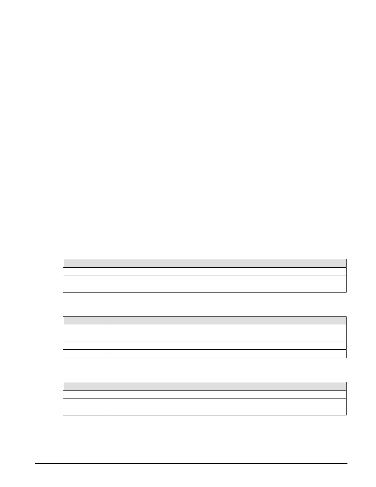
Fault-free operation
Page 48

Troubleshooting
PECON+®
www.epa.de
46 of 48
9 Troubleshooting
9.1 All LEDs remain dark
Ensure that the phase and neutral connector are properly connected and that the device is
supplied with the required voltage.
For the PECON+
®
IT, all three phases must be connected.
A neutral connection is not provided/required.
9.2 Red LED is illuminated
Protective earth connection interrupted
Ensure that the connection between the PE connection on the device and the protective
earth system is adequately low-resistance.
PECON+
®
S1 / S3 / NVF-1 / NVF-2:
Check the assignment of phase and neutral conductor to make sure the L and N polarity
are not switched.
Network phases fault
PECON+
®
IT:
Ensure that all three phases are connected to the device and that they carry the correct
voltage. The voltage difference between the individual phases must not exceed 10% by too
much.
9.3 Service address
Please contact our service department if you have any questions.
EPA GmbH
Fliederstraße 8
63486 Bruchköbel
Germany
Phone: +49 (0) 6181 - 97 04- 0
Fax: +49 (0) 6181 - 97 04- 99
E-mail: [email protected]
Web: www.epa.de
Page 49
System inspection and maintenance
PECON+®
www.epa.de
47 of 48
10 System inspection and maintenance
The function must be checked regularly.
The test key can be used to check whether the protective earth is interrupted.
WARNING
These tests must be carried out by a qualified electrician who is competent to carry out
the tests, has experience of testing and possesses a knowledge based on the testing
of comparable systems.
For the initial test of electrical systems and stationary equipment, the requirements of
the standard DIN VDE 0100-600 "Low-voltage electrical installations – Part 6:
Verification" must be met.
For the repeat test of electrical systems and stationary equipment, the requirements of
the standard DIN VDE 0105-100 "Operation of electrical installations – Part 100:
General requirements" must be met.
Always follow the DGUV Accident Prevention Regulations.
IMPORTANT NOTE
Inspection or maintenance should only be carried out by qualified electricians.
Unless explicitly described in these operating instructions, modifications to the device
may only be carried out by EPA or persons authorised by EPA.
Page 50
Repairs
PECON+®
www.epa.de
48 of 48
11 Repairs
IMPORTANT NOTE
The device can be damaged or destroyed if the instructions are not followed.
Repairs may only be carried out by EPA or repair centres authorised by EPA.
Unauthorised tampering can lead to property damage and will void the warranty
provided by EPA.
The housing should not be opened.
12
Disposal
IMPORTANT NOTE
The
PECON+® is a device intended for commercial use. These devices should not be
disposed of at municipal collection points for electrical appliances. The devices contain
electronic components and must be disposed of properly.
If you have any questions, please contact us.
Page 51

Page 52
Presented by:
All information without liability for correctness and accuracy.
Brands – business names – work titles
Company and product names used by EPA are used only for labling and are mentioned without taking into account any commercial protection right; the lack of the marking of a possibly existent commercial protection right does not mean that the used company and /or product name is available. The EPA logo is a registered trademark for the EPA GmbH.
All rights reserved. Technical changes without notice. Release:
1.6 / 11.2018 Ord. no.: 50275710
 Loading...