

Page 1

Manual control unit for @DRIVE
®
@PAD
®
Quick
start-up
Paramet
erisation
C
ontrol
Instruction manual
Page 2

Legal notice
EPA GmbH
Fliederstraße 8
63486 Bruchköbel
Germany
Phone: +49
(0)6181-9704-0 Fax: +49
(0)6181-9704-99
[email protected]
www.epa.de
Exclusion of liability
All general names, trade names, product names or other
designations used in this manual may be legally protected even if
not labelled as such (e.g. as a trademark). EPA assumes no
liability for their free usage.
The illustrations and texts have been compiled with great care.
However, the possibility of errors cannot be ruled out. The
compilation is made without any guarantee.
General note on gender equality
EPA is aware of how language impacts gender equality and
always makes an effort to reflect this in documentation.
Nevertheless, for the sake of readability, we are unable to use
non-gender-specific terms throughout and use the masculine
form instead.
© 2013 EPA GmbH
Page 3

www.epa.de
All rights reserved by EPA, including those of reproduction by
photocopy and storage in electronic media. Commercial use or
distribution of the texts, displayed models, diagrams and
photographs appearing in this product are not permitted. This
manual may not be reproduced, stored, transmitted or translated
in any form or by means of any media - in whole or in part without prior written permission.
Page 4

www.epa.de
1
Contents
1
Important information ........................................................ 2
1.1 Information about documentation .......................................................... 2
1.1.1
Other applicable documents ....................................................... 2
1.1.2
Storing the documentation ......................................................... 2
1.2
Symbols .......................................................................................... 3
1.2.1
Warnings ............................................................................... 3
1.2.2
Signal words ........................................................................... 3
1.2.3
Information ............................................................................ 3
1.2.4
Text symbols .......................................................................... 3
1.3
Qualified staff .................................................................................. 4
1.4
CE marking ...................................................................................... 4
1.5
Safety instructions ............................................................................. 4
1.5.1
General information ................................................................. 5
1.5.2
Disassembly & disposal .............................................................. 5
1.6
Proper use ...................................................................................... 6
1.7
Responsibility ................................................................................... 6
1.8
Contacts for further information ............................................................ 7
2 Overview of @PAD® ........................................................... 8
2.1 Scope of delivery ............................................................................. 8
2.2
Model description ............................................................................. 8
2.3
Description of @PAD® ......................................................................... 9
2.3.1
Functions .............................................................................. 9
3 Operation ..................................................................... 10
3.1 Function of buttons ........................................................................... 10
3.2
Navigation and input ......................................................................... 11
3.3
Menu ............................................................................................ 12
3.4
Motor detection ............................................................................... 13
3.5
Specifying nominal value for the rotation speed ........................................ 17
3.6
Parameter group menu (expert mode) .................................................... 18
4 Technical data ............................................................... 21
5 Approvals, standards and guidelines .................................... 21
5.1 Standards and guidelines .................................................................... 21
6 List of key words ............................................................ 22
7 Notes ........................................................................... 23
Page 5

www.epa.de
2
1 Important information
This chapter contains important information on safe handling of the
product and the operating manual.
1.1 Information about documentation
The following information explains how to navigate through the
documentation.
Read this manual carefully in its entirety. It contains
important information for operating the @PAD
®
.
We assume no liability for any damage resulting from non-observance of
this manual.
This manual is a part of the product and should be stored in a safe
place. It applies exclusively to the @PAD
®
from EPA GmbH.
Provide the operator of the system with this manual so it is available
when needed.
1.1.1 Other applicable documents
This refers to all manuals that describe how to operate the drive control
system and any other manuals for the equipment used. Download the 3D
files (.stp) for @DRIVE
®
and adapter plates from
www.epa.de.
A description of parameters is available for download
(www.epa.de) for parametrising the drive control system. In the
download, you will find all information required for correct
parametrisation.
1.1.2 Storing the documentation
Store this manual and all other applicable documents safely so they are
available when needed.
Page 6
www.epa.de
3
1.2 Symbols
1.2.1 Warnings
General warnings are labelled by a warning triangle with exclamation
points.
A warning triangle with a lightning bolt indicates the risk of hazardous
voltage.
1.2.2 Signal words
Signal words in warnings indicate the type and severity of the
consequences if measures to avoid danger are not followed.
• DANGER means that life-threatening personal injury can occur.
• WARNING means that severe personal injuries can occur.
• CAUTION means that mild to moderate personal injuries can
occur.
• NOTE means that material damage can occur.
1.2.3 Information
Important information without risks to persons or
property is represented by the symbol on the left.
1.2.4 Text symbols
1, 2, 3,
etc.
Sequential steps of an instruction
Effect of an instruction
Final result of an instruction
Page 7

www.epa.de
4
1.3 Qualified staff
In the context of this operating manual and the information relating to
the product itself, qualified staff refers to electronics specialists who are
familiar with the installation, assembly, start-up and operation of the
drive control and the dangers involved, and whose specialist training and
knowledge of relevant standards and regulations provide them with the
necessary abilities.
1.4 CE marking
With the CE marking, we, as the manufacturer of the device, confirm that
the basic requirements of the following guidelines are met:
• Directive on Electromagnetic Compatibility (Directive
2004/108/EC of the Council)
You can download the Declaration of
Conformity at www.epa.de.
1.5 Safety instructions
The following warnings, precautionary measures and comments are
provided for your safety and serve to prevent damage to the drive control
and the components connected to it. This chapter contains warnings and
information that are generally applicable when handling drive controls.
They are split into general information, transport & storage and
dismantling & disposal.
Specific warnings and comments that apply to specific activities can be
found at the start of the appropriate chapters and are repeated or added
to at various critical points in these chapters.
Please read this information carefully as it is provided for your personal
safety and will also prolong the life of the drive control and connected
devices.
Page 8
www.epa.de
5
1.5.1 General information
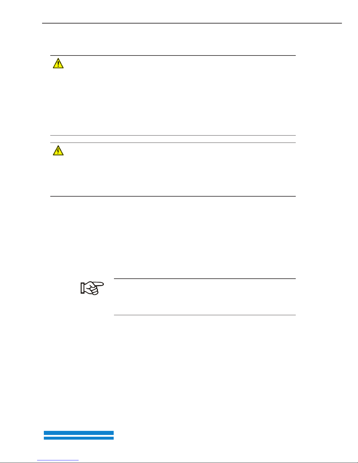
DANGER!
RISK OF DEATH DUE TO ROTATING PARTS!
The motor can rotate during the programming. Depending on the
equipment, this can cause a dangerous situation for persons and the
equipment.
Make sure that no one is located in hazardous zones and that the motor is
disconnected.
DANGER!
RISK OF DEATH DUE TO ELECTRIC SHOCK!
Hazardous currents are present on the motor and drive control. These can
lead to injury or death.
When working on the device, de-energize the device and secure it from
being switched on again.
NOTE
This operating manual must be kept near the device and available to all
users.
1.5.2 Disassembly & disposal
Components with electronic parts may not be disposed
of along with normal household waste. They have to be
collected separately with waste electrical and electronic
equipment in accordance with applicable legislation.
Page 9

www.epa.de
6
1.6 Proper use
The application and performance parameters of the @DRIVE® drive
control from EPA GmbH are displayed and programmed with the @PAD
®
.
This device may only be used for the @DRIVE
®
drive control.
This device may only be used under the allowed environmental
conditions. Incorrect use may cause damage to the device. The @PAD
®
may only be used for its intended purpose. Any use that differs from or
goes beyond the stated intended purpose is considered non-intended
use. The manufacturer accepts no liability for any damage resulting from
such non-intended use. Modifications to the @PAD
®
are prohibited.
Any instance of misuse of the @PAD
®
will result in the termination of
the guarantee, warranty and general liability of the manufacturer.
The @PAD
®
may not be operated in areas where there is a danger
of explosion.
Repairs may only be performed by authorised repair bodies. Independent
and unauthorised intervention may result in death, injury or property
damage. The warranty provided by EPA will be invalidated in such cases.
1.7 Responsibility
As a basic principle, electronic devices are not fail-safe. The operator
and/or the contractor setting up the machine or system is responsible for
ensuring that the drive switches to a safe state if the device fails.
The “Electrical equipment of machines” section in DIN EN 60204-1; VDE
0113-1:2007-06, “Safety of machinery” describes the safety requirements
for electrical control units. These are provided for the safety of people
and machines and must be observed in order to retain the functional
capability of the machine or system.
An emergency stop feature does not have to result in the power supply to
the drive being switched off. To avoid dangerous situations, it may be
useful for individual drives to remain operational or for specific safety
procedures to be initiated. The effectiveness of emergency stop measures
is evaluated by means of a risk assessment for the machine or system and
its electrical equipment, and is determined by selecting a circuit category
according to DIN EN 13849 “Safety of machinery – Safety-related parts of
control systems”.
Page 10

www.epa.de
7
1.8 Contacts for further information
Further information is available from:
Central service hotline
Phone: +49 (0)6181 9704-44
Monday - Friday: 8 am to 16 pm (local time)
E-mail: service@epa.de
Website address
www.epa.de
Page 11
www.epa.de
8
2 Overview of @PAD
®
This chapter contains information on the scope of delivery and the
function description.
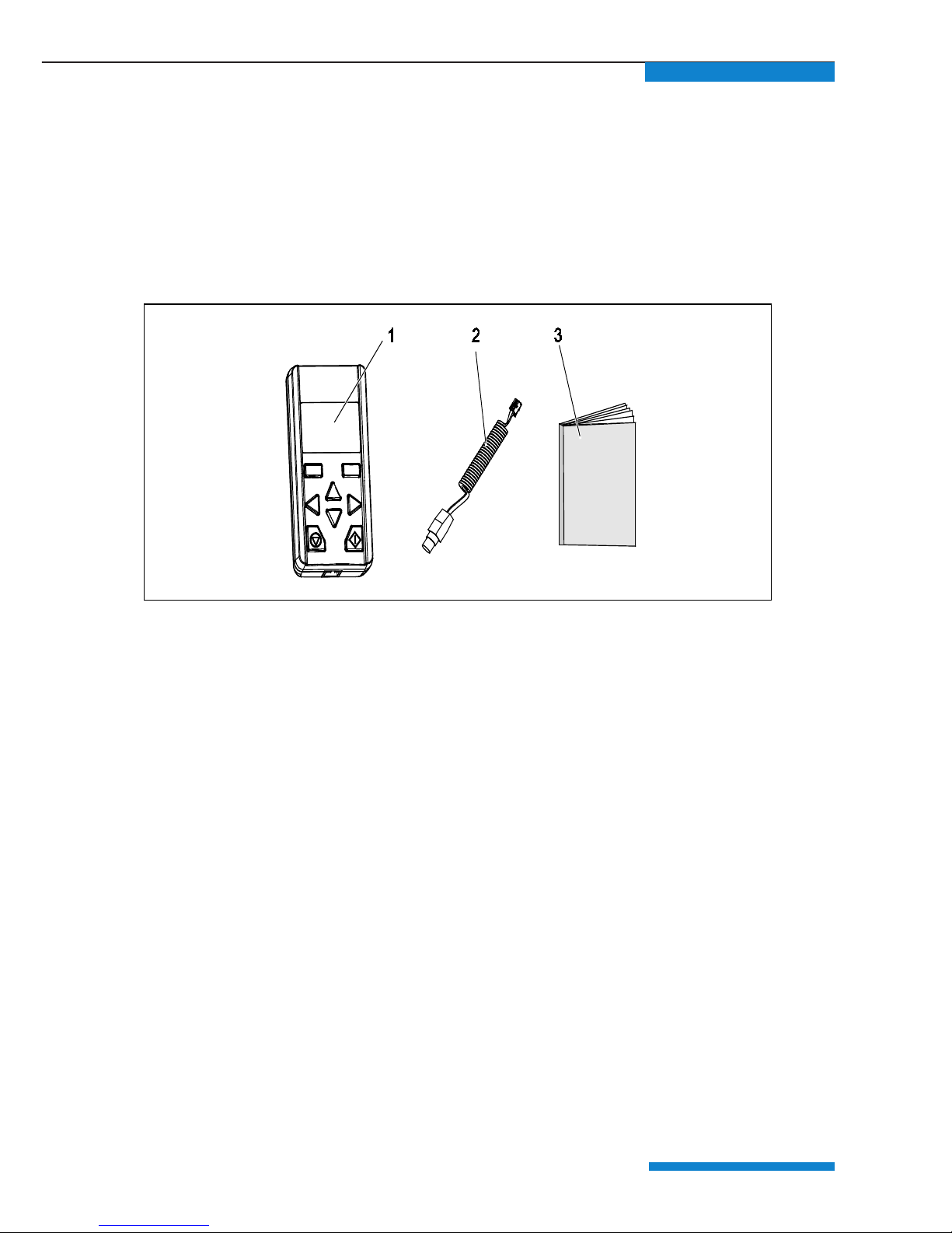
2.1 Scope of delivery
Compare your product with the scope of delivery provided below.
Fig. 1: Scope of delivery
1 @PAD
®
manual control unit
2 Communication cable with RJ11 and M12 plug
3 Brief instruction
2.2 Model description
EPA @PAD®manual control unit for read-out and
parameterizing.
Page 12
www.epa.de
9
2.3 Description of @PAD
®
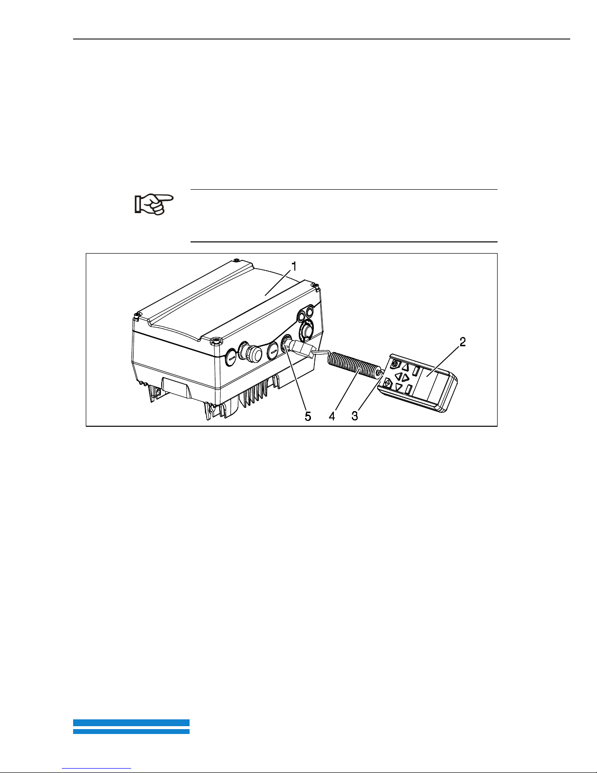
The @PAD® is connected to the @DRIVE® M12 interface. The @PAD
®
displays the parameters. The parameters are programmed with
the function buttons.
Up to eight data records can be stored in an @PAD
®
. The data
records can be copied to other @DRIVEs. The @PAD
®
receives all
signals for programming from the @DRIVE
®
drive control.
The @PAD®may only be operated with
the @DRIVE
®
drive control!
Any other connection is not allowed.
Fig. 3: @PAD® with @DRIVE® drive control
4 Communication cable
5 M12 socket
1 @DRIVE
®
drive control
2 @PAD
®
manual control unit
3 RJ11 socket
2.3.1 Functions
The following functions are possible with the
@PAD
®
:
• Parametrisation of device configuration
• Control (e.g. locking and releasing)
• Display of various process values
• Saving parameter sets (max. 8)
• Transferring parameter sets to different @DRIVEs
Page 13
www.epa.de
10
3 Operation
3.1 Function of buttons
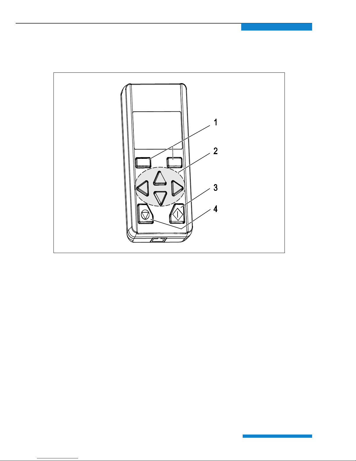
Fig. 4: Button functions
1 Confirm buttons
2 "UP"/"DOWN" buttons
"LEFT" / "RIGHT" buttons
3 Start button
4 Stop button
Page 14
www.epa.de
11
3.2 Navigation and input
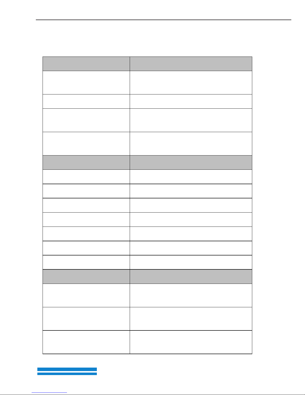
Buttons Function
"UP"/"DOWN" buttons Selecting parameters,
changing values
"LEFT"/"RIGHT" arrows Navigating cursor
Confirm buttons With these buttons, the command showed
in the display is activated via the button
"START"/"STOP"
buttons
With these buttons, the motor is started
or stopped
Commands Procedures
Next Calling up parameters and submenu
Back One menu level higher
Cancel End entry without saving
Change Call up edit mode (cursor blinks)
Save Save selection, entry or change
Enter Confirm the selected parameter set
Start Command for motor detection
Enter Procedures
Displaying tens, hundreds,
thousands place
Press "LEFT" arrow until the desired tens,
hundreds or thousands place is displayed.
Displaying decimal places Press "RIGHT" arrow until the desired
decimal places are displayed.
Entering negative values Place cursor on the plus sign, select the
minus sign with the "UP" arrow and save.
Page 15
www.epa.de
12
3.3 Menu
If the @PAD® is connected to the @DRIVE® and the @DRIVE® is
switched on, the menu appears on the display of the @PAD
®
.
For the Parameter groups menu, there are two modes:
• Standard mode
contains all necessary parameters for standard application from
the factory.
• Expert mode (see menu overview in Chapter 3.6)
Contains advanced parameters for special uses. The expert mode
is activated in the main menu (see Fig. 5: View of main
menu).
The @PAD
®
always starts in standard mode. If the @PAD® is de-
energized, the standard mode is active again.
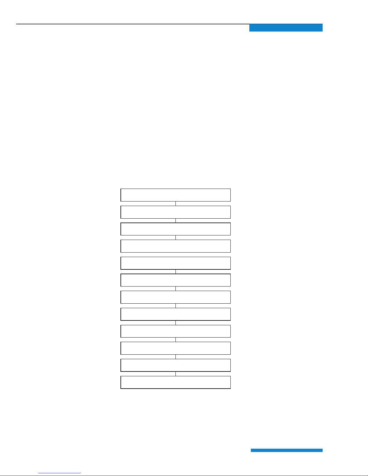
01. Actual values
02. Parameter group
20. Actual fault
21. Fault memory
30. Automatic Motor detection
40. Control
50. Expert mode
80. Read parameter
81 Write parameter
82 Delete parameter
98. SW/HW status
99. Language
Fig. 5: View of main menu
The entire menu is mapped in the @DRIVE
®
operating manual.
Page 16
www.epa.de
13
3.4 Motor detection
DANGER!
RISK OF DEATH DUE TO ROTATING PARTS!
The motor can rotate during the programming. Depending on the
equipment, this can cause a dangerous situation for persons and the
equipment.
Make sure that no one is located in hazardous zones and that the motor is
disconnected.
DANGER!
RISK OF DEATH DUE TO ELECTRIC SHOCK!
When working on the device, de-energize the device and secure it from
being switched on again.
Procedures:
1 De-energize drive control.
2 Unscrew the four screws from the drive control housing cover and
remove the cover.
3 For the hardware enable, connect the 24-volt DC hardware to the
@DRIVE
®
, connect the application board to the "En.HW" terminal.
This voltage can be supplied externally or from
the "24V out" terminal. For these, refer to the
@DRIVE
®
operating manual.
4 Screw the cover onto the drive control housing.
5 Connect the communication cable to the @PAD
®
and the @DRIVE
®
drive control.
6 Switch on the power supply for the drive control.
On the @PAD
®
display, the start screen appears and then
the
menu.
Page 17
www.epa.de
14
The motor type is configured for asynchronous motors
(value 1) by default.
For synchronous motors, the value must be changed to
2. (02.Parameter groups (Expert mode)> Motor
parameter > Motor type)
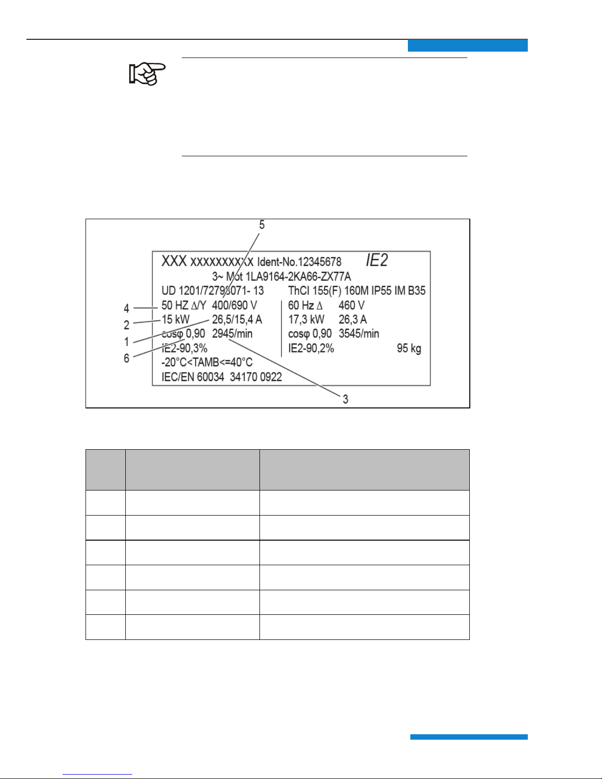
7 Determine the following six motor data from the type plate (see
example)
Fig. 6: Motor type plate (example)
No. Menu item in the @PAD®According to the example on the
template
1. Motor current 26.5 A
2. Motor power 15 kW
3. Motor speed 2,945 rpm
4. Motor frequency 50 Hz
5. Motor voltage 400 V
6. Motor cosφ 0.90
Tab. 1: Determined motor data for motor detection (example)
Page 18
www.epa.de
15
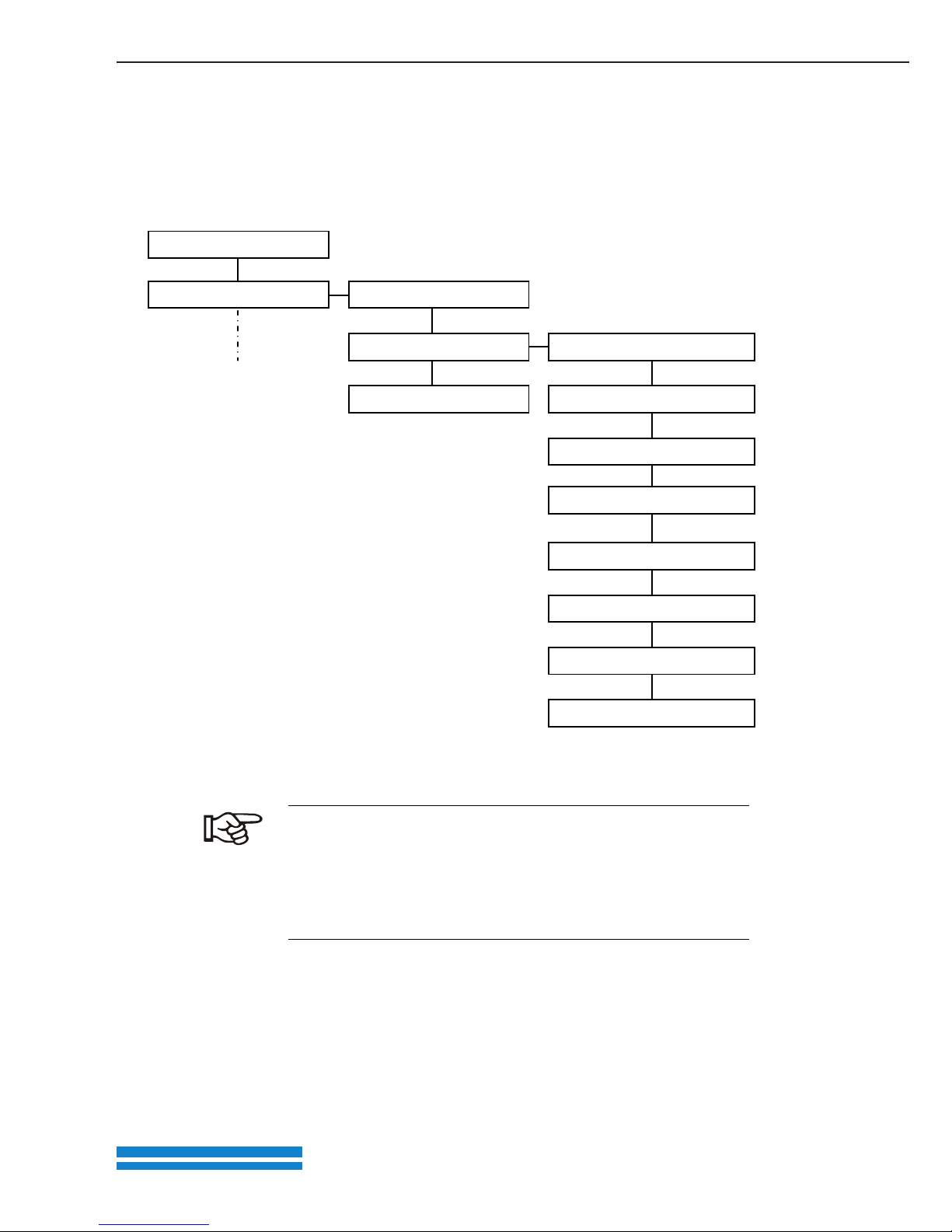
01.Actual values
Basic parameter
Motor parameter
Controller parameter
Motor current [A]
Motor power [W]
Motor speed [rpm]
Motor frequency [Hz]
Stator resistance [Ohm] *
Leakage inductance [H] *
Motor voltage [V]
Motor cos phi
02.Parameter groups
8 Call up the 02.Parameter groups > Motor data menu.
9 Enter and save the six types of motor data from the type plate with
the @PAD
®
under the corresponding menu items. (The values for
"stator resistance" and "leakage induct." are determined during motor
detection.)
*) These values are automatically determined and entered during motor detection.
Fig. 7: View of menu structure for motor data
Always observe the following during motor detection!
Asynchronous motor: The shaft must not rotate during
motor detection.
Synchronous motor: The shaft must be unencumbered
since it occasionally rotates during motor detection.
10 Call up the 30.Automatic Motor detection menu and start motor
detection.
Page 19
www.epa.de
16
Red and green LEDs light up during motor detection
Motor detection lasts 30 - 60 seconds. Motor
detection is completed when the @DRIVE
®
is
restarted and the green LED on @DRIVE
®
lights up
continuously.
If the @PAD®is unplugged from the M12 interface
during the active controlling process, the @DRIVE
®
stops with error 21 (Bus Time-Out) and the red LED
lights up continuously.
The motor detection is completed.
Page 20
www.epa.de
17
3.5 Specifying nominal value for the rotation speed
With the @PAD®, a nominal value (in %) can be specified for the
rotation speed. This nominal value is specified as a percentage
of the nominal motor rotation speed.
The ACTUAL rotation speed can be read on the display. With the "START"
and "STOP" button, the motor is switched on and off.
If the minimum frequency is > 0, the motor continues to
rotate at the minimum frequency after switching off the
nominal value. (02Parameter group (Expert
mode)>Basic parameter>Low speed)
Procedures
1 As the nominal value source, set "3: MMI/PC" (02.Parameter groups >
Basic parameter > Reference channel)
2 As the software enable signal, set "9: "Autostart" and save
(02.Parameter groups > Basic parameter > Enable software )
3 Under the menu item "40.Control", set a nominal value in %. Using the
"UP", "DOWN", "LEFT" or "RIGHT" arrows, set the desired percentage.
A negative nominal value causes a change in direction
of rotation
.
4 Press the "START" button and start the motor.
The motor rotates. The actual rotation speed is displayed in the
@PAD
®
.
With the @PAD
®
, the motor can be switched on and off
and a
nominal rotation speed can be specified.
Page 21
www.epa.de
18
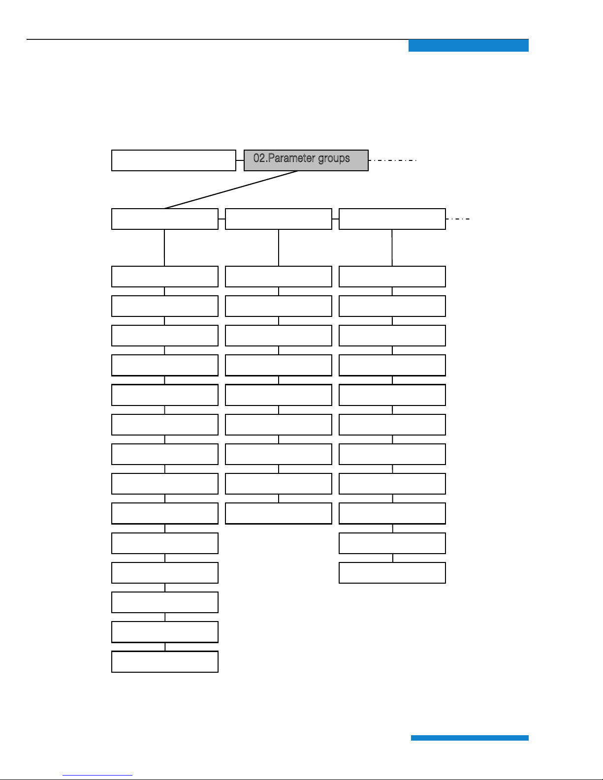
3.6 Parameter group menu (expert mode)
In expert mode, the "0.2 Parameter group" menu contains advanced
parameters for special applications. The expert mode is activated in the
main menu (see Fig. 5: View of main menu).
Fig. 8: View of parameter group (expert mode) – Part 1
01.Actual values
Basic parameter Control mode Process controller
Low speed
High speed
Deceleration 1
Acceleration 1
Deceleration 2
Acceleration 2
Ramp selection
Ref.channel
02.Parameter groups
Enable software
Start protect
Rotation direction
Reset
Automatic reset
Quan.auto.reset
Preset speed mode
Preset speed 1
Preset speed 7
MOP digital in.
MOP step range
MOP step time
MOP resp.time
MOP ref.memory
PID prop.gain
PID prop.gain
PID prop.gain
PID feedback
PID inverted
PID preset ref. 1
…
PID preset ref. 1
PID ref.mode
PID standby time
PID std.by hyst.
…
Page 22
www.epa.de
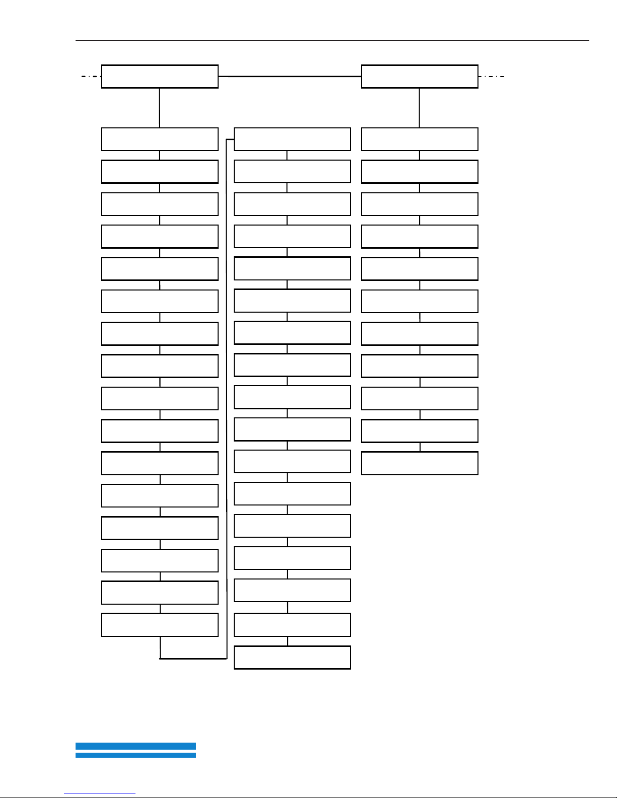
19
Fig. 9: View of parameter group (expert mode) – Part 2
Control terminal
AI1 ref.type
AI1 min.input
AI1 max.input
AI1 dead time
AI1 filter time
AI1 function
AI1 phy.unit
AI2 ref.type
AI1 min.input
AI2 max.input
AI2 dead time
AI2 filter time
AI2 function
AI2 phy.unit
AO1 function
AO1 min.output
AI1 max.input
DO1 function
DO1 on
DO1 off
DO2 function
DO1 on
DO1 off
Relay1 function
Relay1 on
Relay1 off
Relay1 on delay
Relay1 off delay
Relay2 function
Relay2 on
Relay2 off
Relay2 on delay
Relay2 off delay
Special function
External fault 1
External fault 2
Curr.limit.[%]
Curr.limit.[s]
Factor gearbox
Stall detection
Stall time
Para. set change
Tech.parameter1
…
Tech.parameter20
Page 23
www.epa.de
20
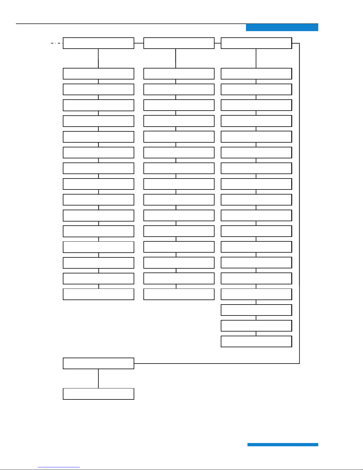
*) These values are automatically determined and entered during motor detection.
Fig. 10: View of parameter group (expert mode) – Part 3
Brake chopper
Brake chopper
Field.parameter
SAS/SPF address
SAS baud rate
Fieldbus address
Fieldbus baud rate
Bus timeout
Fieldbus language
Ref-feed.diff.
Tolerance range
Reference value
Process data out 3
…
Process data out 10
Process data in 3
…
Processdata in 6
Motor type
i2t fac.mot.
I2T time
Opt.stat.resist.
Motor current
Motor power
Motor speed
Motor frequency
Motor resistance *
Leakage induct. *
Motor voltage
Motor cos phi
Holding current time
Stator induct. *
Nominal flux
Controller
Control method
Encoder type
Enc.line count
Encoder offset
Flying restart
Switching frequency
Speed control Kp
Speed control Tn
Slip trimmer
Squared charac.
Flux compensation
Motor parameter
Volt.contr.res.
Field weakening
Startup current
Init.time PMSM
Start.mode PMSM
Start.ramp PMSM
Startup frequency
Page 24
www.epa.de
21
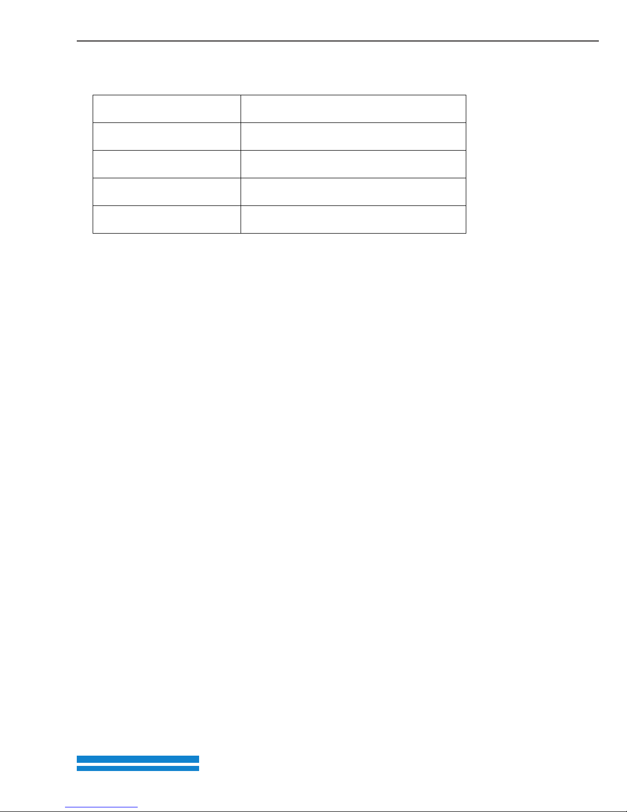
4 Technical data
Article number 71049001
Connection cable 3m RJ11 on M12 plug
Measurement (L / W / H) 105/50/25 mm
Weight 83 g
Protection class IP21
Tab. 2: Technical data
5 Approvals, standards and guidelines
This chapter contains information about the respective approvals,
standards and guidelines.
For binding information about the particular approvals, please refer to
the relevant type plate!
5.1 Standards and guidelines
The following specifically apply:
– Directive on Electromagnetic Compatibility (Directive 2004/108/EC of
the Council EN 61800-3:2004)
Page 25

www.epa.de
22
6 List of key words
C
CE marking ........................... 4
Configuring nominal value ........ 17
D
Disposal .............................. 5
E
EC Declaration of Conformity ...... 4
EMC limit classes .................. 21
EMC standard ...................... 21
Expert mode ........................ 18
F
Functions of buttons .............. 10
I
Information .......................... 7
Initial operation ..................... 13
L
Legal notice ..........................
M
Menu ................................. 12
Menu structure for motor data ... 15
N
Navigation ........................... 11
O
Operation ............................ 10
P
Parameter group (expert mode) . 18
Parametrisation ..................... 2
Proper use ............................ 5
R
Regulations .......................... 5
S
Safety instructions ................... 4
Standard mode ...................... 12
Standards ............................ 21
T
Technical data ...................... 21
Page 26

www.epa.de
23
7 Notes
Page 27

Page 28
EPA GmbH
Fliederstraße 8, D-63486 Bruchköbel
Deutschland / Germany
Telefon / Phone: +49 (0) 6181 9704 - 0
Telefax / Fax: +49 (0) 6181 9704 - 99
E-Mail: [email protected]
Internet: www.epa.de
Brands – business names – work titles
Company and product names used by EPA are used only for labeling and are mentioned without taking into account any commercial protection right; the lack of the marking of a possibly existent
commercial protection right does not mean that the used company and /or product name is available. The EPA logo is a registered trademark for the EPA GmbH.
All rights reserved. Technical changes without notice. Release: 09-2013 Ord. no.: 50275568
All information without libalility for correctness and accuracy.
Presented by:
 Loading...