

Page 1
Leakage current compensation for single-phase devices
Instruction manual
Fixed value
compensation of
50 Hz operational
leakage currents
at 5 / 10 mA
Can be used on
RCCBs with a
rated fault current
I
∆n
= 30 mA
or higher
according to
DIN VDE 0100-530
Page 2

LEAKCOMP® 1C
www.leakcomp.de
1
of
34
Thank you for choosing the LEAKCOMP
®
1C leakage current compensation unit from
EPA.
If you have any technical questions, please give us a call:
Phone: +49 (0)6181 – 9704 – 0
For the latest information on this product, visit www.leakcomp.de and www.epa.de.
Page 3

LEAKCOMP® 1C
www.leakcomp.de
2
of
34
Contents
1 Important basic information ........................................................................................... 4
1.1 Publication details .................................................................................................. 4
1.2 Target group........................................................................................................... 5
1.3 Liability ................................................................................................................... 5
1.4 General equal treatment ......................................................................................... 5
1.5 Registered trademarks ........................................................................................... 5
1.6 Symbols and signal words ...................................................................................... 6
1.7 Marking on the product ........................................................................................... 7
1.8 CE mark ................................................................................................................. 7
1.9 EMC Limit Class ..................................................................................................... 7
1.10 Declaration of Conformity ....................................................................................... 8
1.11 Product description................................................................................................. 9
1.12 Delivery contents .................................................................................................. 10
2 Safety instructions ...................................................................................................... 11
2.1 Intended use of the unit ........................................................................................ 11
2.2 Requirements for personnel ................................................................................. 13
2.3 Responsibility: ...................................................................................................... 13
2.4 Connection ........................................................................................................... 14
2.5 Follow the operating instructions .......................................................................... 15
3 Technical data ................................................................................................................ 16
3.1 Rating................................................................................................................... 16
3.2 Dimensions .......................................................................................................... 17
4 Function ......................................................................................................................... 18
4.1 Functional description .......................................................................................... 18
4.2 Analysis of RCCB utilisation ................................................................................. 19
4.3 Comparing leakage current with and without the LEAKCOMP
®
1C ....................... 20
5 Delivery, internal transport, unpacking ........................................................................ 21
5.1 Delivery ................................................................................................................ 21
5.2 Internal transport .................................................................................................. 21
5.3 Unpacking ............................................................................................................ 21
6 Storage and transport ................................................................................................... 22
6.1 Ambient conditions ............................................................................................... 22
6.2 Storage ................................................................................................................ 22
6.3 Transport .............................................................................................................. 22
7 Installation ..................................................................................................................... 23
7.1 Safety instructions for installation ......................................................................... 23
7.2 Installation conditions ........................................................................................... 24
7.3 Connections
............
............................................................................................. 26
Page 4

LEAKCOMP® 1C
www.leakcomp.de
3
of
34
7.4 Wiring diagram ..................................................................................................... 27
8 Startup / Operation ........................................................................................................ 29
8.1 Switching on ......................................................................................................... 29
8.2 Switch compensation on and off ........................................................................... 29
8.3 Shutdown ............................................................................................................. 29
8.4 LED display elements ........................................................................................... 30
8.5 Setting the compensation current ......................................................................... 30
8.6 Further increasing the compensation current........................................................ 30
9 Troubleshooting ............................................................................................................ 31
9.1 Blue LED remains off ........................................................................................... 31
9.2 Red LED is flashing .............................................................................................. 31
9.3 RCCB trips ........................................................................................................... 32
9.4 Service address ................................................................................................... 32
9.5 Fault detection and rectification ............................................................................ 33
10 System inspection and maintenance ........................................................................... 34
11 Repairs ........................................................................................................................... 34
12 Disposal ......................................................................................................................... 34
Page 5

Important basic information
LEAKCOMP® 1C
www.leakcomp.de
4
of
34
1
Important basic information
1.1 Publication details
Published by:
EPA GmbH
Fliederstr. 8
63486 Bruchköbel
Germany
Phone: +49 (0) 6181 – 9704 -0
Fax: +49 (0) 6181 – 9704 -99
E-mail: [email protected]
Web: www.epa.de | www.leakcomp.de
Author:
T. Bozem
Implementation:
K. Bonkosch, A. Meyer
Issue number:
1.5 / 04/2018
Validity of device version:
LEAKCOMP® 1C
HW 1.2
© EPA GmbH
All rights, including the rights to photomechanical reproduction and storage in electronic
media, are reserved by EPA GmbH. Commercial use or distribution of the text, models,
drawings and photos used in this product are not permitted. No part of this publication
may be reproduced, stored or transferred, distributed or translated in any form or using
any medium without prior written permission.
Page 6

Important basic information
LEAKCOMP® 1C
www.leakcomp.de
5
of
34
1.2 Target group
This documentation is intended for qualified personnel as defined in IEC 60364.
Qualified personnel are persons who have the appropriate qualifications for the work to be
performed during the installation, assembly, startup and operation of the product.
1.3 Liability
The common names, trade names, descriptions of goods and other designations used in
this publication may be legally protected even if not specifically marked as such (for
example as trademarks). EPA GmbH accepts no liability or warranty for their free
availability.
The illustrations and text were compiled with the utmost care. Nevertheless, errors cannot
be excluded.
The publication is provided without guarantee.
The information it contains is provided solely for the purpose of customer information and
contains no representations or binding warranties. Binding statements are possible only in
response to specific inquiries.
The contents of this instruction manual are accurate at the date of printing. Since it is
under continuous development, the manufacturer reserves the right to change the
specification of the product and its performance data as well as the contents of this
instruction manual, in both technical and commercial terms, without prior notice. The
current version is available at www.LEAKCOMP.de or www.EPA.de.
Liability of the company EPA GmbH for any damage resulting from incorrect use of this
instruction manual or incorrect, erroneous or inappropriate installation or adjustment is
excluded. Interruptions to operation, loss of profit as well as loss of information and data
or consequential damages are excluded insofar as liability is not mandatory in accordance
with the law on product liability or in cases of intent, gross negligence or breach of
fundamental contractual obligations.
1.4 General equal treatment
EPA GmbH is aware of the importance of language with respect to the equal rights of
women and men and makes every effort to take this into account. To ensure better
readability, however, it was necessary to abstain from the consistent use of differentiated
formulations.
1.5 Registered trademarks
Brand names and trademarks are the property of their respective owners and are not
generally marked as such in this manual.
The absence of such marking does not mean that a name is free within the meaning of
brand and trademark law.
Page 7
Important basic information
LEAKCOMP® 1C
www.leakcomp.de
6
of
34
1.6 Symbols and signal words
The following symbols and signal words are used in this documentation to indicate
hazards and important information:
Symbol/signal word
Meaning
Warning of hazardous electrical voltage
DANGER
Draws your attention to a hazardous situation that will
result in serious injury or death if not avoided.
WARNING
Draws your attention to a hazardous situation that may
result in serious injury or death if not avoided.
CAUTION
Draws your attention to a hazardous situation that may
result in minor to moderate injury if not avoided.
IMPORTANT NOTE
Draws your attention to the handling and impact of safety
information.
NOTE
Draws your attention to the handling and impact of safety
information.
Draws your attention to possible damage to property and
other important information.
The installation must be carried out by a qualified
electrician (IEC 60417-6182).
Page 8
Important basic information
LEAKCOMP® 1C
www.leakcomp.de
7
of
34
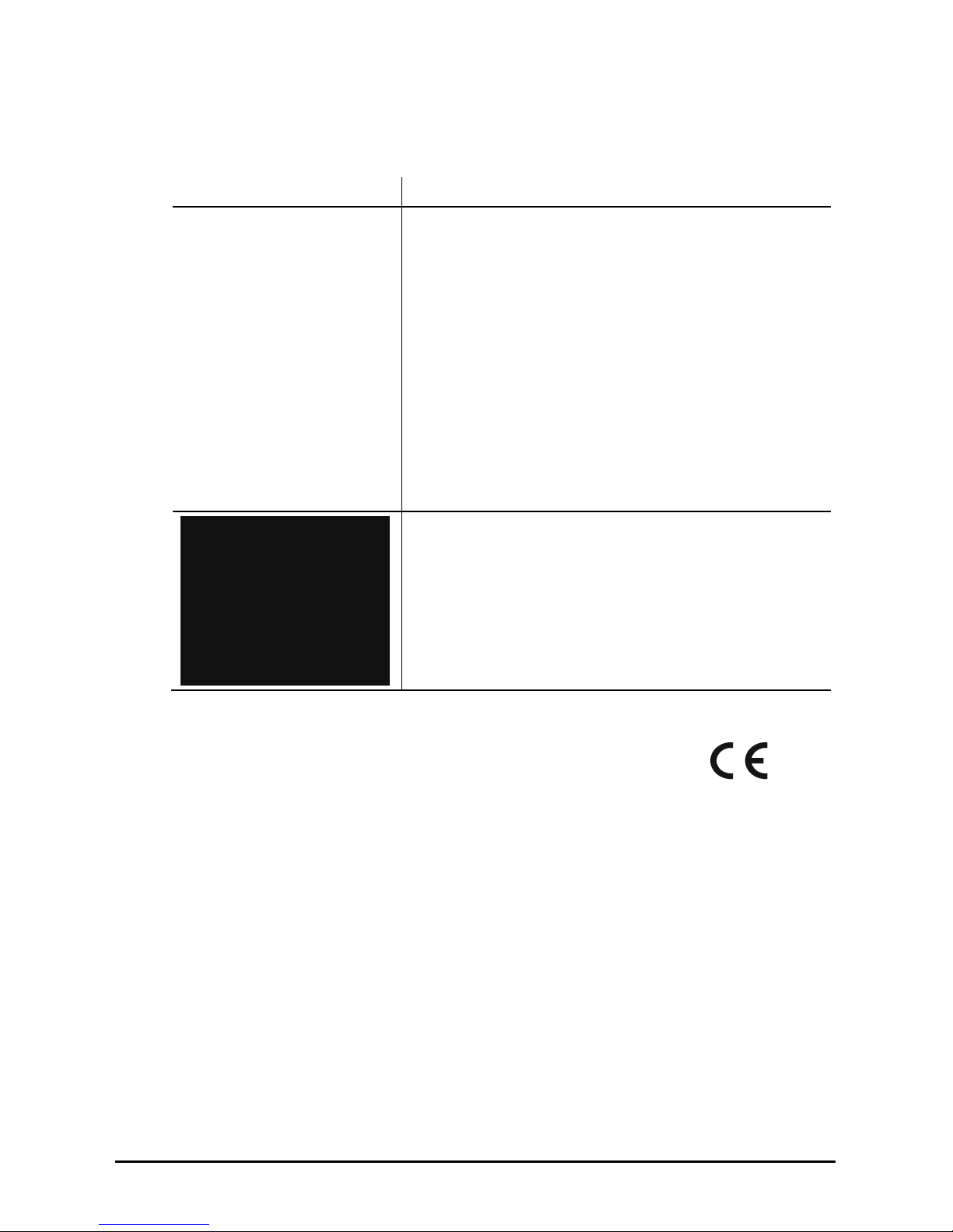
1.7 Marking on the product
Illustration
Description
LED displays
Blue LED: Status display
(RUN)
Red LED: Error display
(ERROR)
Terminal assignment
Mains connection (phase and neutral conductor): L / N
Protective earth conductor / compensation: PE
Compensation selection 5 mA or 11 mA: C1 / C2
Type plate
Manufacturer’s details and technical data
1.8 CE mark
The CE mark is on the device nameplate.
The device complies with the relevant essential requirements of all applicable EU
directives. The declaration of conformity can be found in the chapter “Declaration of
conformity”.
1.9 EMC Limit Class
LEAKCOMP
®
1C meets the limit values for emitted interference according to DIN EN
55011 / CISPR 11 Class B Group 1. The interference immunity corresponds to DIN EN
61000-6-2.
The device is classified in accordance with DIN EN 61326-1 (VDE 0843-20-1) and is
suitable for use in residential, business and commercial areas as well as in industrial
environments.
Page 9

Important basic information
LEAKCOMP® 1C
www.leakcomp.de
8
of
34
1.10 Declaration of Conformity
Page 10

Important basic information
LEAKCOMP® 1C
www.leakcomp.de
9
of
34
1.11 Product description
There is an increasing use of residual current circuit breakers in industry for personal
safety and fire protection. Modern components used in automation technology generate
leakage currents when the system is operating. These so-called “operational” leakage
currents are interpreted by the RCDs as differential currents and thus often lead to
unreliable operating states or to their complete shutdown. The residual current circuit
breaker cannot distinguish between the operational leakage currents and true fault
currents.
The EPA LEAKCOMP
®
1C compensates capacitive currents with a frequency of 50 Hz,
which occur due to EMC filtering of single-phase consumers (such as those that occur
with power supplies, frequency converters, UPSs, lamps, mains filters, etc.)
The LEAKCOMP
®
1C leakage current compensation unit is used in electrical plants,
machines or devices that cause 50 Hz leakage currents and are to be operated on
residual current circuit breakers (RCCBs).
The LEAKCOMP
®
1C compensates for the leakage currents occurring with single-phase
consumers during operation preventing inadvertent or ‘nuisance’ tripping of residual
current devices caused by excessively high 50 Hz leakage currents. The device works
with all common RCCBs of the types A, F, B and B+ (ideally with short-term delay; a
suitable type must be chosen according to the regulations!).
The size of the 50-Hz-compensation current is set at 5 mA and can be increased to 11 mA
via a jumper. If the compensation current is not sufficient to compensate for the leakage
current, additional LEAKCOMP
®
1C devices can be connected in parallel.
The LEAKCOMP
®
1C has two LED indicators.
The blue LED functions as the operating display and indicates the presence of the power
supply and fault-free operation. Reversed phase and neutral conductors, high neutral
conductor voltage (potential difference between neutral and protective earth conductor) or
the absence of the protective earth conductor on the LEAKCOMP
®
1C is indicated by the
red LED.
IMPORTANT NOTE
Along with 50 Hz leakage currents, leakage currents of other frequencies can also
occur that are not compensated by the LEAKCOMP
®
1C. EPA also offer a suitable
solution for these cases.
For leakage current measurement with analysis of the utilisation of the residual
current circuit breaker, we recommend using the leakage current analysis system
EPA LEAKWATCH (more information at www.leakwatch.de).
Page 11
Important basic information
LEAKCOMP® 1C
www.leakcomp.de
10
of
34
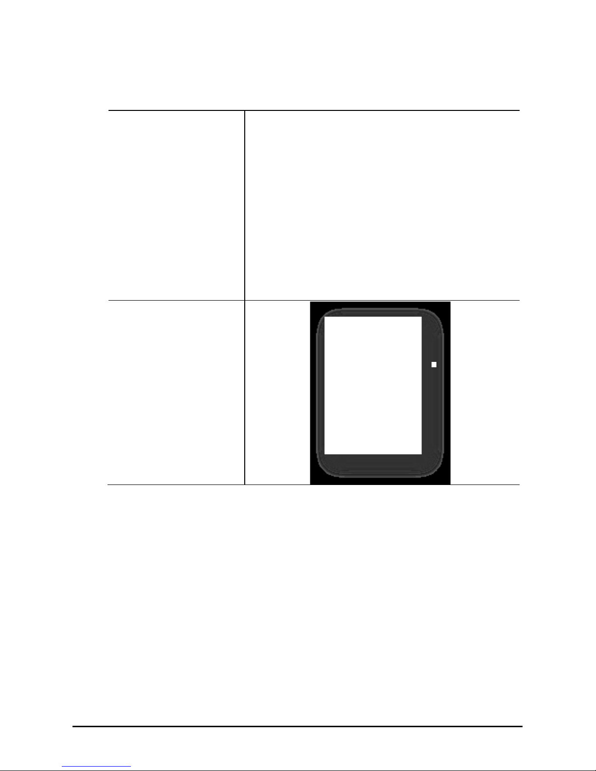
1.12 Delivery contents
Leakage current
compensation unit
LEAKCOMP
®
1C
EPA Article No.:
50275675
Operating manual
LEAKCOMP
®
1C
EPA Article No.:
50275681
Page 12

Safety instructions
LEAKCOMP® 1C
www.leakcomp.de
11
of
34
2
Safety instructions
2.1 Intended use of the unit
Area of application
The EPA LEAKCOMP
®
1C compensates capacitive currents with a frequency of 50 Hz
that occur due to EMC filtering of single-phase consumers.
The LEAKCOMP
®
1C leakage current compensation unit is used in electrical plants,
machines or devices that cause 50 Hz leakage currents and are to be operated on
residual current circuit breakers (RCCBs).
The LEAKCOMP
®
1C compensates for the leakage currents occurring with single-phase
consumers during operation preventing inadvertent or ‘nuisance’ tripping of residual
current devices caused by excessively high 50 Hz leakage currents. The device works
with all common RCCBs of the types A, F, B and B+ (ideally with short-term delay; a
suitable type must be chosen according to the regulations!).
IMPORTANT NOTE
Operational leakage currents can accept frequencies ≠ 50 Hz and cause a
malfunction of the residual current device.
Continued on next page
Page 13
Safety instructions
LEAKCOMP® 1C
www.leakcomp.de
12
of
34
Continued
Inadmissible operating conditions
DANGER
To prevent overcompensation, it is important that the LEAKCOMP
®
1C is always
switched on and off together with the leakage current generator.
Overcompensation is inadmissible, i.e. the compensation current must not be higher
than the leakage current.
A stand-alone operation without a leakage current generator is not permissible.
CAUTION
The LEAKCOMP
®
1C must only be used under the conditions and for the purposes for
which it was designed (see also “Intended use” chapter).
Particular attention should be paid to the safety instructions and the technical data
setting out the ambient conditions.
Operational safety is not guaranteed in the event of modification or improper use.
High voltage differences between the neutral conductor and the protective earth
conductor can overload or destroy the device.
Strong electromagnetic fields can affect the function of the device.
External mechanical loads are not allowed.
IMPORTANT NOTE
The device is not suitable for:
• The reduction of ≠ 50 Hz leakage currents,
• The reduction of 150 Hz operational leakage currents on three-phase devices
(servo or frequency inverters),
• The reduction of operational leakage currents for the purpose of compliance with
maximum permitted limits for leakage currents (e.g. 3.5 mA limit for mobile
devices) in compliance with EN 50178 and 10 mA limit for machines in compliance
with EN 60204-1),
• The reduction of leakage currents higher than those specified for the device,
• Use on AC-type residual current circuit breakers (prohibited in Germany!),
• Systems/machines with power regeneration.
• Potentially explosive atmospheres.
Page 14

Safety instructions
LEAKCOMP® 1C
www.leakcomp.de
13
of
34
2.2 Requirements for personnel
WARNING
Installation and work on the LEAKCOMP
®
1C may only be carried out
by qualified personnel.
Qualified personnel as defined by this instruction manual are electricians
who are familiar with the installation, assembly, startup and operation of the device,
with the hazards involved, and who, based on their technical training, are also familiar
with the relevant standards and provisions.
Repairs may only be carried out by authorised repair centres. Unauthorised tampering
can lead to property damage and will void the warranty provided by EPA GmbH.
2.3 Responsibility:
WARNING
Electronic devices are never fail-safe. The installer and/or operator of the machine or
system is responsible for ensuring that the system/machine is restored to a safe state if
the device fails or the residual current device is tripped.
The safety requirements for electrical controllers are set out in DIN EN 60204-1; VDE
0113-1 "Safety of machinery" in the section titled "Electrical equipment of machines".
These provisions ensure the safety of persons and machines as well as the
maintenance of the functional capability of the machine or system and must be
observed.
Page 15

Safety instructions
LEAKCOMP® 1C
www.leakcomp.de
14
of
34
2.4 Connection
WARNING of hazardous electrical voltage
Risk to life from electric shocks! Death or serious injury!
To avoid electric shock, take appropriate precautions.
Follow the accident prevention regulations for electrical systems and equipment when
carrying out all work.
WARNING
Terminals C1 and C2 are intended solely for controlling the LEAKCOMP
®
1C. These
must not be used for any other purpose.
The potential at terminals C1 and C2 is at level N (neutral conductor) of the mains
voltage. For safety reasons, the relay contacts (if used) must therefore have a
dielectric strength of at least 230 VAC, and the connecting cables/jumpers at C1 and
C2 must be insulated accordingly.
CAUTION
The device must be supplied with the voltage specified in the technical data. Higher
voltages higher can destroy the device.
Surge voltages between the terminals can destroy the device.
The device must be fixed firmly into place while the power supply is disconnected and
no parts are live.
The LEAKCOMP® 1C must have a fixed, low-impedance connection with the protective
earth conductor (PE).
The LEAKCOMP
®
1C must only be used in TN-S networks.
Page 16

Safety instructions
LEAKCOMP® 1C
www.leakcomp.de
15
of
34
2.5 Following the operating instructions
IMPORTANT NOTE
Please read this manual carefully. It contains important information about the
installation and operation of the LEAKCOMP
®
1C.
The LEAKCOMP
®
1C has been subjected to extensive testing and left the factory in a
technically and operationally safe condition. To maintain this condition, the user must
follow the safety instructions in this manual.
We assume no liability for damage caused by failure to follow these instructions.
This manual is an integral part of the product and is valid only for the
LEAKCOMP
®
1C leakage current compensation unit manufactured by EPA GmbH.
Please pass this manual on to the system operator/end customer/service technician so
that it is available when required.
Keep these operating instructions and all other applicable documents in a safe place to
ensure that they are available when required.
This is a translation of the original German instruction manual.
Page 17

Technical data
LEAKCOMP® 1C
www.leakcomp.de
16
of
34
3
Technical data
3.1 Rating
Network configuration
TN-S system (L / N / PE)
Rated voltage
230 VAC ±10%, single phase
Rated frequency
50 Hz ± 1%
Compensation frequency
50 Hz ± 1%
Compensation current
max. 11 mA (RMS)
selectable: 5 mA or 11 mA (with jumper
C1-C2)
Power loss
<2 VA
Ambient temperature
Operation: -10...+40ºC
Storage: -20...+75ºC
Transport: -20...+75ºC
Rel. humidity
<80%, without condensation
Atmospheric pressure
70..106 kPa
Dimensions
17.5 x 90 x 56.4 mm
Weight
Approx. 65 g
Mounting / fitting
on DIN EN 50022 mounting rail, position as required
Connections
Mains connection:
L N
Protective earth conductor / compensation connection: PE
Selection of compensation current 5 / 11 mA:
C1 C2
Cable cross-section: max. 2.5 mm² (14 AWG) massive
max. 1.5 mm² (16 AWG) flexible with sleeve
Max. tightening torque
0.8 Nm
Displays
Blue LED: Operating/status display
(RUN)
Red LED: Error display
(
ERROR)
Protection class
IP20
Direct contact protection
DGUV V3 (BGV A3)
Flammability
UL94 V-0
Housing material
PA
EMV
EN 61326-1, EN 55011 (Class B), EN 61000-6-2
Safety
EN 61010-1
Conformity
CE, RoHS (2011/65/EU)
Page 18

Technical data
LEAKCOMP® 1C
www.leakcomp.de
17
of
34
3.2 Dimensions
All dimensions are specified in mm. Tolerance ±1 mm. Subject to change.
Current CAD files can be downloaded at www.epa.de.
Page 19

Function
LEAKCOMP® 1C
www.leakcomp.de
18
of
34
4
Function
4.1 Functional description
Initial situation
There is an increasing use of RCDs for personal safety-and fire protection purposes. The
modern components used in automation technology (such as frequency inverters, RFI
filters, switching power supplies, shielded motor cables etc.) generate leakage currents
when the system is operating. These so-called "operational" leakage currents are
interpreted by the protective devices as differential currents and therefore often lead to
unreliable operating states in the residual current device or the complete shutdown of the
system. The residual current circuit breaker cannot distinguish between the operational
leakage currents and true fault currents.
Application
To prevent the unwanted tripping of the residual-current circuit breaker (RCCB), a device
is needed that can compensate for capacitive leakage currents with a frequency of 50 Hz.
The leakage current compensation device LEAKCOMP
®
1C was specially developed for
this purpose (compensation current selectable 5 or 11 mA). It is used in electrical systems
or machines in which (mostly single-phase) devices with an integrated EMC filter are
connected to residual current devices (RCDs) or residual current circuit breakers (RCCBs)
with rated residual currents of I
Δn
= 30 mA or higher (according to DIN VDE 0100- 530).
LEAKCOMP
®
1C
The LEAKCOMP
®
1C compensates for operational leakage currents occurring in the
system/machine and thus prevents the inadvertent or unwanted tripping of RCDs caused
by excessively high 50 Hz leakage currents.
This functionality is available for all common RCCBs of the types A, F, B and B+ (shorttime delayed [STD] versions are recommended). The size of the 50-Hz-compensation
current is set at 5 mA and can be increased to 11 mA via a jumper. If the compensation
current is not sufficient to compensate for the leakage current, additional LEAKCOMP
®
1C
devices can be connected in parallel.
The LEAKCOMP
®
1C has two LED indicators.
The blue LED functions as the operating display and indicates the presence of the power
supply and fault-free operation.
The red LED indicates a device fault. The following faults are detected:
• Reversal of the phase and neutral conductors
• Lack of protective earth conductor
• High neutral conductor voltage
Page 20

Function
LEAKCOMP® 1C
www.leakcomp.de
19
of
34
4.2 Analysis of RCCB utilisation
For leakage current measurement with an analysis of the RCCB utilisation, we
recommend using the leakage current analysis system EPA LEAKWATCH (more
information at www.leakwatch.de).
LW-NETBOOK LW-SET-MZ
LW-Soft
Page 21
Function
LEAKCOMP® 1C
www.leakcomp.de
20
of
34
4.3 Comparing leakage current with and without the LEAKCOMP® 1C
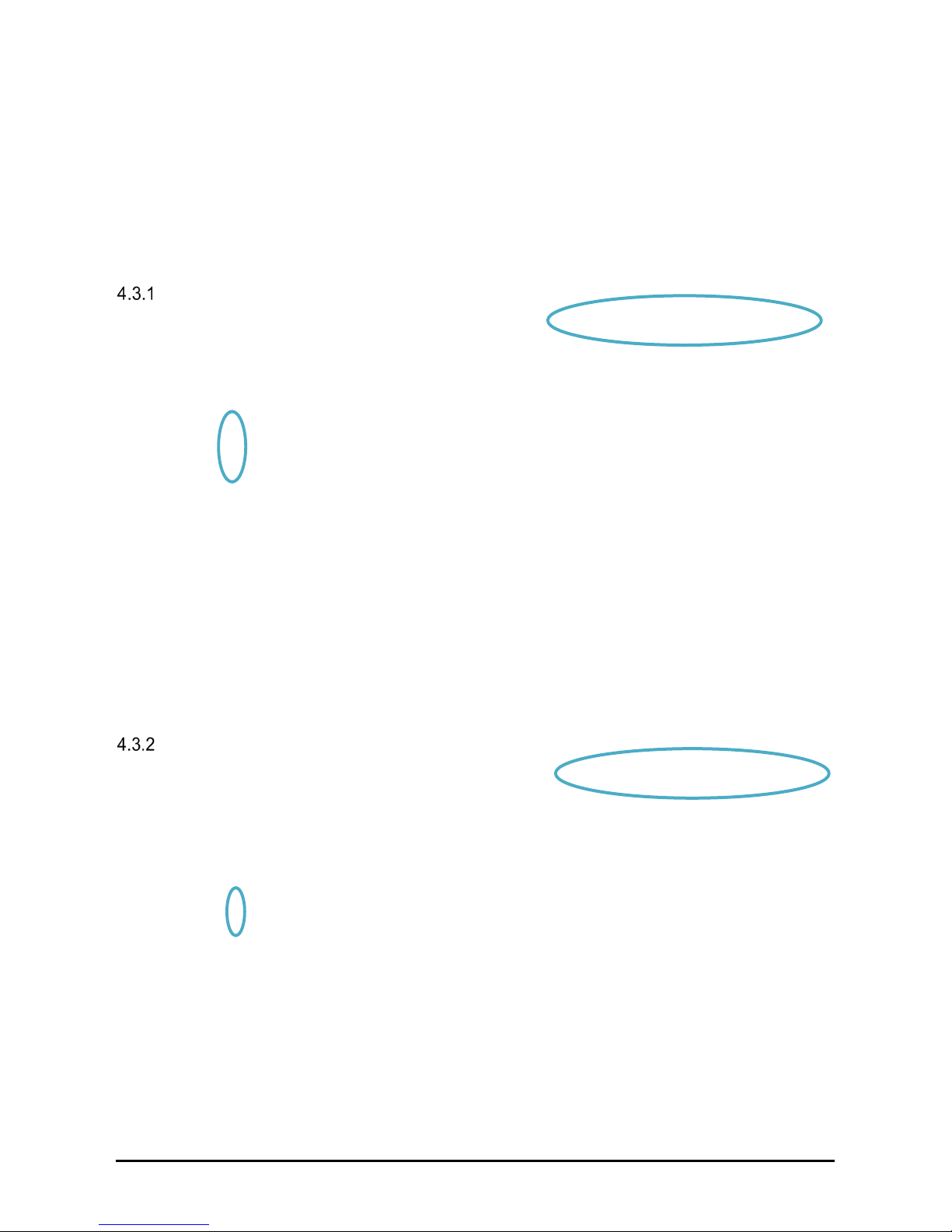
Below is an example of a Fast Fourier Transformation (FFT) for determining the frequency
and amplitude of the leakage current. A commercial single-phase switching power supply
with integrated EMC mains filter was measured. The red line shows the tripping threshold
of a 30 mA RCCB (here EPA RCCB1).
Leakage current without the LEAKCOMP® 1C
The measured 50 Hz leakage current in this example is 20.9 mA and the utilisation of the
RCCB is 76%.
Since a 30 mA residual current device can already trigger normatively at 15 mA (50% of
the rated residual current I
Δn
), this value must be viewed with a critical eye.
To ensure that the RCCB works reliably, the leakage current at 50 Hz should be less than
15 mA, if possible.
► The RCCB cannot work reliably! Tripping due to the high 50 Hz leakage current is very
likely.
Leakage current with the LEAKCOMP® 1C
The measured 50 Hz leakage current in this example is 10.8 mA and the utilisation of the
RCCB is 37%.
With the LEAKCOMP
®
1C, the 50 Hz leakage current is reduced to 10.8 mA and is thus
below the possible tripping threshold of 15 mA (50% of the rated fault current I
Δn
).
► The RCCB cannot work reliably! No further tripping due to the 50 Hz leakage current.
Page 22

Delivery, internal transport, unpacking
LEAKCOMP® 1C
www.leakcomp.de
21
of
34
5
Delivery, internal transport, unpacking
5.1 Delivery
For the components included in delivery, please refer to the section titled "Delivery
contents".
All LEAKCOMP
®
1C have been subjected to extensive testing and have left the factory in
a technically and operationally safe condition.
WARNING
Read the operating instructions carefully before use.
5.2 Internal transport
The device must be protected against external influences for transport (knocks, vibration,
temperature, dirt etc.). The transport conditions are set out in the section titled "Storage
and transport".
5.3 Unpacking
IMPORTANT NOTE
Check the unit for external damage.
Please keep the original packaging and operating instructions.
Page 23
Storage and transport
LEAKCOMP® 1C
www.leakcomp.de
22
of
34
6
Storage and transport
6.1 Ambient conditions
CAUTION
Damage possible
Risk of damage to the unit from improper storage or transport.
NOTE
If the unit has been transported at extreme temperatures, it requires an
acclimatisation period of at least 2 hours before operation.
Strong vibrations, knocks, shocks and soiling (liquids and solid foreign bodies) must
be avoided at all times as they can cause damage to the unit.
6.2 Storage
Always ensure that the LEAKCOMP
®
1C is stored in a correct and proper manner.
The unit must be stored in a dry, enclosed space.
6.3 Transport
Where possible, transport the LEAKCOMP
®
1C properly in its original packaging.
The packaging included in delivery can be used for transport.
Storage
-25°C to +55°C (EN 60721-3-1, 1K3)
Transport
-25°C to +70°C (EN 60721-3-1, 2K3)
Moisture and humidity
Condensation not allowed, relative humidity ≤ 80%
Soiling
Pollution degree 2 (EN 50178)
Page 24

Installation
LEAKCOMP® 1C
www.leakcomp.de
23
of
34
7
Installation
7.1 Safety instructions for installation
DANGER
Warning of hazardous electrical voltage!
Risk to life from electric shocks! Death or serious injury!
Take appropriate precautions to prevent electric shocks.
DANGER
The LEAKCOMP
®
1C must only be installed by an authorised and qualified specialist
who is familiar with the relevant safety provisions.
Work in hazardous proximity to electrical systems should only be performed under the
instruction of a responsible electrician and not carried out alone.
Follow the accident prevention regulations for electrical systems and equipment when
carrying out all work.
Installation should only be carried while the power supply is disconnected and no parts
in the system are live.
The LEAKCOMP
®
1C is designed for mounting on a rail in accordance with DIN 50022.
The device must be firmly installed in the distribution board.
The housing of the LEAKCOMP
®
1C must not be opened.
WARNING
To prevent overcompensation, it is important that the LEAKCOMP
®
1C is always
switched on and off together with the leakage current generator.
An overcompensation is inadmissible, i.e. the compensation current must not be
higher than the leakage current.
Continued on next page
Continued
Page 25
Installation
LEAKCOMP® 1C
www.leakcomp.de
24
of
34
WARNING
The LEAKCOMP
®
1C must be connected in parallel to the "leakage generator".
The protective conductor (PE) must be connected to the protective conductor terminal
(PE) of the device with a fixed, low-impedance connection.
The LEAKCOMP
®
1C must only be used in TN-S networks.
IMPORTANT NOTE
When tightening the terminals, the maximum tightening torque of 0.8 Nm must not be
exceeded.
7.2 Installation conditions
WARNING
Follow the safety instructions in the section titled "Safety" and note the technical data in
the section titled "Technical data".
Operating conditions
The LEAKCOMP
®
1C operates independently of position and is designed for mounting on
a top-hat rail in accordance with DIN 50022.
It is designed for single-phase TN-S networks (L//N/PE).
Ambient conditions
Operation
+10°C to +40°C
Moisture and humidity
Without condensation, relative humidity ≤ 80%
Installation altitude
≤ 2000 m above sea level
Soiling
Pollution degree 2 (EN 50178)
Page 26
Installation
LEAKCOMP® 1C
www.leakcomp.de
25
of
34
Connection conditions
WARNING of hazardous electrical voltage
Risk to life from electric shocks! Death or serious injury!
To avoid electric shock, take appropriate precautions.
Follow the accident prevention regulations for electrical systems and equipment when
carrying out all work.
WARNING
The internal control voltage at terminals C1 and C2 is intended solely for controlling
the LEAKCOMP
®
1C. It must not be used for any other purpose!
The potential of the control voltage is on level N of the mains voltage.
For safety reasons, the connecting cables must therefore have a dielectric strength of
at least 230 VAC and the jumpers at C1 and C2 must be insulated accordingly.
CAUTION
The device must be supplied with the voltage specified in the technical data. Higher
voltages higher can destroy the device.
The device must be fixed firmly into place while the power supply is disconnected and
no parts are live.
Improper wiring can destroy the device.
Page 27

Installation
LEAKCOMP® 1C
www.leakcomp.de
26
of
34
7.3 Connections
Power supply
On the LEAKCOMP
®
1C, a phase (L), the neutral conductor (N) and the protective earth
conductor (PE) must be connected in parallel to the electrical installation.
When selecting the phase, it must be ensured that it also supplies the "leakage current
generator", as compensating is impossible otherwise.
The phase and neutral conductor must be properly connected and must not be reversed.
Reversed phase and neutral conductors is indicated by the red LED (ERROR).
Compensation connection
The compensation connection (PE) on the LEAKCOMP
®
1C must be connected to the
protective conductor in a permanent and low-resistance manner. If the connection is
removed, this is indicated by the red LED (ERROR).
Control connection
The magnitude of the compensation current can be selected with a jumper between
control terminals C1 and C2.
If terminals C1 and C2 are open, the compensation current is 5 mA RMS.
If terminals C1 and C2 are connected (jumper provided from factory), the compensation
current is 11 mA RMS.
Page 28
Installation
LEAKCOMP® 1C
www.leakcomp.de
27
of
34
7.4 Wiring diagram
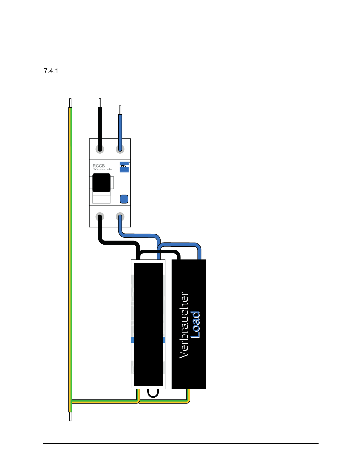
Standalone operation
Wiring the LEAKCOMP
®
1C to an RCCB.
Page 29
Installation
LEAKCOMP® 1C
www.leakcomp.de
28
of
34
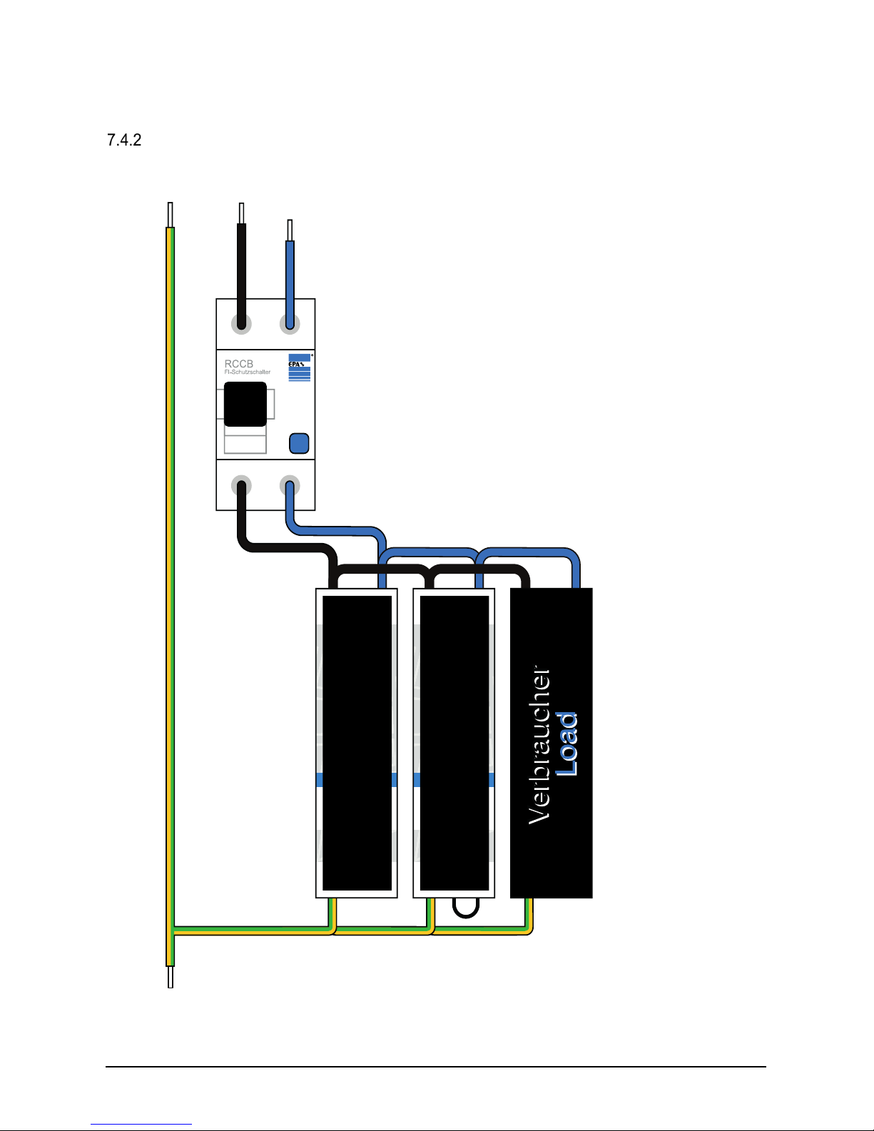
Parallel operation
Wiring of two LEAKCOMP
®
1C operated in parallel to an RCCB.
Page 30

Startup / Operation
LEAKCOMP® 1C
www.leakcomp.de
29
of
34
8
Startup / Operation
DANGER
To prevent overcompensation, it is important that the LEAKCOMP
®
1C is always
switched on and off together with the leakage current generator.
An overcompensation is inadmissible, i.e. the compensation current must not be
higher than the leakage current.
IMPORTANT NOTE
The level of the compensation current (5 mA or 11 mA) must be selected before
commissioning the LEAKCOMP
®
1C.
To successfully deploy the LEAKCOMP
®
1C, it is necessary to first identify the
devices that are responsible for the leakage current and thus for tripping the RCCB. In
addition, the level of the leakage current before and after using the LEAKCOMP
®
1C
should be measured in order to determine whether the compensation was successful
(see chapter “Comparing leakage current with and without the LEAKCOMP
®
1C”).
8.1 Switching on
When the supply voltage is switched on, the device first carries out a self-test, which
detects and if necessary corrects the correct assignment of the phase (L) and neutral
conductors (N) and the presence of the protective earth conductor (PE).
If phase and neutral are reversed or the protective earth conductor is missing, the red
LED flashes.
If too high of a potential difference between the neutral and protective earth conductor is
identified, then this is also detected by the LEAKCOMP
®
1C and indicated by a flashing
red LED.
The blue LED serves as an operating display. A pulsating blue LED indicates that the
mains voltage is present, as well as proper connection of the phase, neutral conductor
and protective earth conductor and fault-free operation.
8.2 Switch compensation on and off
Compensation can be switched on and off by interrupting the conductor PE at the
compensating line.
8.3 Shutdown
To shut down the LEAKCOMP
®
1C, disconnect the power supply to terminals L and N.
Page 31
Startup / Operation
LEAKCOMP® 1C
www.leakcomp.de
30
of
34
8.4 LED display elements
The LEAKCOMP
®
1C has two colour LED indicators.
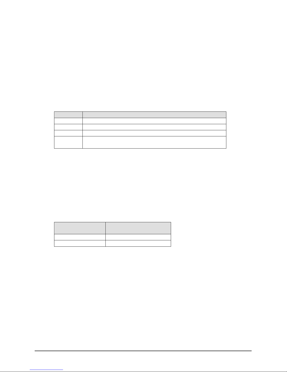
Display
Status
Blue LED
Fault-free operation
Red LED
Phase and neutral reversed
Red LED
Protective earth conductor not connected
Red LED
High potential difference between neutral and protective earth
conductor
8.5 Setting the compensation current
The LEAKCOMP
®
1C provides fixed compensation, meaning that the compensation
current is set to a fixed value for the respective application.
With an optimal compensation current level, the resulting 50 Hz leakage current is almost
zero.
The level of the compensation current can be selected with a jumper between terminals
C1 and C2. If terminals C1 and C2 are open, the compensation current is 5 mA RMS. If a
jumper is provided between C1 and C2 (from factory), the compensation current is 11 mA
RMS.
Compensation
current
Control terminals C1 and
C2
5 mA
open
11 mA
bridged
8.6 Further increasing the compensation current
If the compensation current is not sufficient to compensate for the leakage current,
additional LEAKCOMP
®
1C devices can be connected in parallel.
Using a second LEAKCOMP
®
1C it is possible to generate 16 mA or 22 mA compensation
currents.
You must still ensure that no overcompensation occurs.
Page 32

Troubleshooting
LEAKCOMP® 1C
www.leakcomp.de
31
of
34
9
Troubleshooting
9.1 Blue LED remains off
The blue LED serves as an operating display. A pulsating blue
LED indicates that the mains voltage is present, as well as
proper connection of the phase (L), neutral conductor (N) and
protective earth conductor (PE) and fault-free operation.
è Make sure that the phase, neutral and protective earth
conductors are correctly connected and the mains supply
between phase and neutral conductor is present.
9.2 Red LED is flashing
Incorrect phase allocation
When the supply voltage is switched on, the device first carries
out a self-test, which detects and if necessary corrects the
correct assignment of the phase (L) and neutral conductors (N).
If phase and neutral are swapped, the red LED flashes.
è Ensure that the phase and neutral are connected correctly
and not reversed.
Protective earth conductor missing
The proper connection of the protective earth conductor to the PE terminal is determined
during the self-test of the LEAKCOMP
®
1C. The compensation current can only flow if the
protective earth conductor is connected to the compensation connection of the device. If
the protective earth conductor is not connected to the PE terminal on the LEAKCOMP
®
1C, the red LED flashes.
è Make sure the protective earth conductor is firmly connected to the compensation
connection on the LEAKCOMP
®
1C with low resistance.
Neutral conductor voltage
If too high of a potential difference between the neutral and protective earth conductor is
identified, then this is also detected by the LEAKCOMP
®
1C and indicated by a flashing
red LED.
è Please measure the voltage between the neutral and protective earth conductors with
a suitable measuring device. If there is voltage between the neutral and protective
earth conductors, there is an installation problem with the system wiring that must be
dealt with before the starting the LEAKCOMP
®
1C. This does not generally cause a
defect in the device.
WARNING
In the event of a permanently raised voltage (>10V) between the neutral and
protective earth conductors or terminals N and COMP, a defect may occur in the
LEAKCOMP
®
1C.
Page 33

Troubleshooting
LEAKCOMP® 1C
www.leakcomp.de
32
of
34
9.3 RCCB trips
The RCCB may trip if the compensation current is set either too high or too low.
An optimal ratio of compensation current to leakage current is required for safe operation
at the RCCB. This must be checked metrologically.
Along with 50 Hz leakage currents, leakage currents of other frequencies can also occur
that are not compensated by the LEAKCOMP
®
1C (e.g. 150 Hz or leakage currents in the
kHz range). EPA also offer a suitable solution for these cases.
We recommend measuring the leakage current on the output side of the RCCB. The
leakage current analysis system EPA LEAKWATCH (further information at
www.leakwatch.de) can be used to measure the leakage current and analyse the
utilisation of the RCCB.
9.4 Service address
EPA GmbH
Fliederstraße 8
63486 Bruchköbel
Germany
Phone: +49 (0) 6181 – 97 04 0
Fax: +49 (0) 6181 – 97 04 99
Email: [email protected]
Web: www.epa.de
Page 34

Troubleshooting
LEAKCOMP® 1C
www.leakcomp.de
33
of
34
9.5 Fault detection and rectification
Fault/error message
Possible cause(s)
Remedy
RCCB trips, despite the
use of the LEAKCOMP
®
1C.
Wiring error – neutral
conductor tapped before
residual current circuit breaker
Check wiring and tap N after
residual current circuit breaker
Compensation current is too
low
Increase compensation current;
Insert jumper C1-C2;
Switch additional LEAKCOMP
®
1C
(s) in parallel
Compensation current is too
high
Reduce compensation current;
Remove jumper C1-C2;
50 Hz leakage current due to
insulation fault
Correct insulation fault
High leakage current at
150 Hz
Compensate leakage current of
three-phase inverter
(e.g. EPA LEAKCOMP
®
HP)
EMC filter /mains filter
with high leakage current
Use low-leakage current filters
(e.g. EPA NF-1ph-FSE)
High leakage currents in the
range of the inverter switching
frequency
Use additional mains filters to
reduce high-frequency leakage
currents (e.g. EPA NF-DAR, NF-KCDAR)
Leakage current too high (with
unknown frequency)
Carry out a leakage current analysis
(e.g. with EPA LEAKWATCH)
Red LED is flashing
Phase and neutral reversed
Check assignment of phase and
neutral conductor on LEAKCOMP
®
1C and change wiring if necessary
No protective conductor
connection
Check for presence of protective
earth conductor and ensure a lowresistance connection to the
compensation terminal
High neutral conductor
voltage
Check voltage between neutral and
protective earth conductor and
eliminate potential difference, if any
Both LEDs are off
No power supply
Check voltage supply at terminals L
and N
Device defective
Send the LEAKCOMP® 1C to EPA
Page 35

System inspection and maintenance
LEAKCOMP® 1C
www.leakcomp.de
34
of
34
10
System inspection and maintenance
WARNING
These tests must be carried out by a qualified electrician who is competent to carry out
the tests, has experience of testing and possesses a knowledge based on the testing
of comparable systems.
For the initial test of electrical systems and stationary equipment, the requirements of
the standard DIN VDE 0100-600 "Low-voltage electrical installations – Part 6:
Verification" must be met.
For the repeat test of electrical systems and stationary equipment, the requirements of
the standard DIN VDE 0105-100 "Operation of electrical installations – Part 100:
General requirements" must be met.
Always follow the accident prevention regulations.
IMPORTANT NOTE
When used as intended, the LEAKCOMP
®
1C is maintenance-free.
Inspection or maintenance should only be carried out by qualified electricians.
Unless explicitly described in these operating instructions, modifications to the device
may only be carried out by EPA or persons authorised by EPA.
11
Repairs
IMPORTANT NOTE
The LEAKCOMP
®
1C can be damaged or destroyed if the instructions are not followed.
Repairs may only be carried out by EPA or repair centres authorised by EPA.
Unauthorised tampering can lead to property damage and will void the warranty
provided by EPA.
The housing should not be opened.
12
Disposal
IMPORTANT NOTE
The LEAKCOMP
®
1C is a device intended for commercial use. These devices should
not be disposed of at municipal collection points for electrical appliances. The devices
contain electronic components and must be disposed of properly. If you have any
questions, please contact us.
Page 36
Presented by:
All information without liability for correctness and accuracy..
Brands – business names – work titles
Company and product names used by EPA are used only for labling and are mentioned without taking into account any commercial protection right; the lack of the marking of a possibly existent
commercial protection right does not mean that the used company and /or product name is available. The EPA logo is a registered trademark for the EPA GmbH.
All rights reserved. Technical changes without notice. Release: 1.5 / 04.2018 Ord. no.: 50275700
EPA GmbH
Fliederstraße 8, D-63486 Bruchköbel
Deutschland / Germany
Telefon / Phone: +49 (0) 6181 9704 - 0
Telefax / Fax: +49 (0) 6181 9704 - 99
E-Mail: [email protected]
Internet: www.epa.de
 Loading...