

EPA digitax st User Manual
AC variable speed drive
for servo motors
User Guide

Original Instructions
For the purposes of compliance with the EU Machinery Directive 2006/42/EC:
General Information
The manufacturer accepts no liability for any consequences resulting from inappropriate, negligent or incorrect installation or
adjustment of the optional operating parameters of the equipment or from mismatching the variable speed drive with the motor.
The contents of this guide are believed to be correct at the time of printing. In the interests of a commitment to a policy of continuous
development and improvement, the manufacturer reserves the right to change the specification of the product or its performance, or
the contents of the guide, without notice.
All rights reserved. No parts of this guide may be reproduced or transmitted in any form or by any means, electrical or mechanical
including photocopying, recording or by an information storage or retrieval system, without permission in writing from the publisher.
Drive software version
This product is supplied with the latest software version. If this drive is to be connected to an existing system or machine, all drive
software versions should be verified to confirm the same functionality as drives of the same model already present. This may also
apply to drives returned from an Emerson Industrial Automation Service Centre or Repair Centre. If there is any doubt please contact
the supplier of the product.
The software version of the drive can be checked by looking at Pr 11.29 and Pr 11.34. This takes the form of xx.yy.zz where Pr 11.29
displays xx.yy and Pr 11.34 displays zz. (e.g. for software version 01.01.00, Pr 11.29 = 1.01 and Pr 11.34 displays 0).
Environmental statement
Emerson Industrial Automation is committed to minimising the environmental impacts of its manufacturing operations and of its
products throughout their life cycle. To this end, we operate an Environmental Management System (EMS) which is certified to the
International Standard ISO 14001. Further information on the EMS, our Environmental Policy and other relevant information is
available on request, or can be found at:
http://www.emersonindustrial.com/en-EN/controltechniques/aboutus/environment/Pages/environment.aspx
The electronic variable-speed drives manufactured by Emerson Industrial Automation have the potential to save energy and (through
increased machine/process efficiency) reduce raw material consumption and scrap throughout their long working lifetime. In typical
applications, these positive environmental effects far outweigh the negative impacts of product manufacture and end-of-life disposal.
Nevertheless, when the products eventually reach the end of their useful life, they must not be discarded but should instead be
recycled by a specialist recycler of electronic equipment. Recyclers will find the products easy to dismantle into their major component
parts for efficient recycling. Many parts snap together and can be separated without the use of tools, while other parts are secured
with conventional fasteners. Virtually all parts of the product are suitable for recycling.
Product packaging is of good quality and can be re-used. Large products are packed in wooden crates, while smaller products come
in strong cardboard cartons which themselves have a high recycled fibre content. If not re-used, these containers can be recycled.
Polythene, used on the protective film and bags for wrapping product, can be recycled in the same way. Emerson Industrial
Automations' packaging strategy prefers easily-recyclable materials of low environmental impact, and regular reviews identify
opportunities for improvement.
When preparing to recycle or dispose of any product or packaging, please observe local legislation and best practice.
REACH legislation
EC Regulation 1907/2006 on the Registration, Evaluation, Authorisation and restriction of Chemicals (REACH) requires the supplier
of an article to inform the recipient if it contains more than a specified proportion of any substance which is considered by the European
Chemicals Agency (ECHA) to be a Substance of Very High Concern (SVHC) and is therefore listed by them as a candidate for
compulsory authorisation.
For current information on how this requirement applies in relation to specific Emerson Industrial Automations’ products, please
approach your usual contact in the first instance. Emerson Industrial Automations’ position statement can be viewed at:
www.emersonindustrial.com/en-EN/controltechniques/aboutus/environment/reachregulation/Pages/reachregulation.aspx.
Copyright © September 2015 Emerson Industrial Automation.
The information contained in this guide is for guidance only and does not form part of any contract. The accuracy cannot be guaranteed
as Emerson have an ongoing process of development and reserve the right to change the specification of their products without notice.
Control Techniques Limited. Registered Office: The Gro, Newtown, Powys SY16 3BE. Registered in England and Wales. Company
Reg. No. 01236886.
Moteurs Leroy-Somer SAS. Headquarters: Bd Marcellin Leroy, CS 10015, 16915 Angoulême Cedex 9, France. Share Capital: 65 800
512 €, RCS Angoulême 338 567 258.
Issue Number: 5
Software: 01.06.00 onwards
For patent and intellectual property related information please go to: www.ctpatents.info.
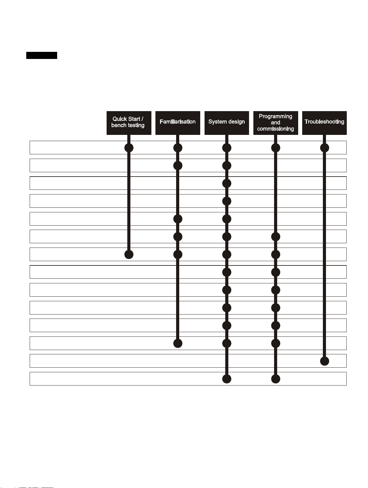
How to use this guide
NOTE
1 Safety information
2 Product information
3 Mechanical installation
4 Electrical installation
5 Getting started
6 Basic parameters
7 Running the motor
8 Optimization
9 SMARTCARD operation
11 Advanced parameters
12 Technical data
13 Diagnostics
14 UL listing information
10 Onboard PLC
This User Guide provides information for operating the drive from start to finish.
The information is in logical order, taking the reader from receiving the drive through to fine tuning the performance.
There are specific safety warnings throughout this guide, located in the relevant sections. In addition, Chapter 1 Safety
Information on page 6 contains general safety information. It is essential that the warnings are observed and the
information considered when working with or designing a system using the drive.
This map of the user guide helps to find the right sections for the task you wish to complete:

Contents
1 Safety Information .................................6
1.1 Warnings, Cautions and Notes .............................6
1.2 Electrical safety - general warning ........................6
1.3 System design and safety of personnel ................6
1.4 Environmental limits ..............................................6
1.5 Access ...................................................................6
1.6 Fire protection .......................................................6
1.7 Compliance with regulations .................................6
1.8 Motor .....................................................................6
1.9 Mechanical brake control ......................................6
1.10 Adjusting parameters ............................................6
1.11 Electrical installation ..............................................6
2 Product information ..............................8
2.1 Introduction ...........................................................8
2.2 Drive ratings ..........................................................8
2.3 Drive model numbers ............................................9
2.4 Drive nameplate description ..................................9
2.5 Features of the drive ...........................................10
2.6 Options ................................................................11
2.7 Items supplied with the drive ...............................14
3 Mechanical installation .......................15
3.1 Safety information ...............................................15
3.2 Planning the installation ......................................15
3.3 Solutions Module / keypad installation / removal 16
3.4 Drive dimensions .................................................17
3.5 External EMC filter rating ....................................18
3.6 Optional braking resistor .....................................19
3.7 Terminal torque settings ......................................20
3.8 Routine maintenance ..........................................20
4 Electrical installation ...........................21
4.1 Power terminal connections ................................22
4.2 Ground connections ............................................23
4.3 AC supply requirements ......................................23
4.4 DC bus design .....................................................24
4.5 DC drive voltage levels .......................................24
4.6 Ratings ................................................................25
4.7 Output circuit and motor protection .....................25
4.8 Braking ................................................................26
4.9 Ground leakage ...................................................27
4.10 EMC (Electromagnetic compatibility) ..................28
4.11 Internal and external conducted emissions
conformity ............................................................30
4.12 Serial communications connections ....................31
4.13 Control connections ............................................32
4.14 Control terminals .................................................34
4.15 Encoder connections ...........................................37
4.16 Encoder terminals ...............................................38
4.17 Safe Torque Off ...................................................42
5 Getting started .................................... 43
5.1 User interfaces ................................................... 43
5.2 CT Soft ............................................................... 43
5.3 SYPTPro (Indexer & Plus only) .......................... 43
5.4 EZMotion PowerTools Pro ................................. 43
5.5 Keypad operation ............................................... 44
5.6 Understanding the display .................................. 44
5.7 Displaying parameters with non-default
values only ......................................................... 47
5.8 Displaying destination parameters only ............. 47
5.9 Communications ................................................ 47
6 Basic parameters ................................ 49
6.1 Single line descriptions ...................................... 49
6.2 Full descriptions ................................................. 54
7 Running the motor .............................. 60
7.1 Quick start Connections ..................................... 60
7.2 Quick Start set-up .............................................. 64
7.3 Setting up a feedback device ............................. 65
7.4 Setting up a buffered encoder output ................. 68
8 Optimization ........................................ 69
8.1 Motor map parameters ....................................... 69
9 EtherCAT interface ............................. 72
9.1 Features ............................................................. 72
9.2 What is EtherCAT? ............................................ 72
9.3 EtherCAT interface information .......................... 72
9.4 EtherCAT interface terminal descriptions ........... 72
9.5 Module grounding .............................................. 72
9.6 Network topology ............................................... 72
9.7 Minimum node-to-node cable length .................. 72
9.8 Quick start guide ................................................ 72
9.9 Quick start flowchart ........................................... 74
9.10 Saving parameters to the drive .......................... 75
9.11 EtherCAT interface Node address ..................... 75
9.12 EtherCAT interface RUN .................................... 75
9.13 Re-initializing the EtherCAT interface ................ 75
9.14 Process Data Objects (PDOs) ........................... 75
9.15 Service Data Object (SDO) parameter access .. 75
9.16 CANopen over EtherCAT (CoE) ........................ 76
9.17 Ethernet over EtherCAT (EoE) ........................... 80
9.18 Drive profile (DSP-402) support ......................... 81
9.19 Interpolated position mode ................................. 87
9.20 vl velocity mode .................................................. 88
9.21 Profile torque mode ............................................ 90
9.22 Homing mode ..................................................... 91
9.23 Cyclic sync position mode .................................. 94
9.24 Advanced features ............................................. 94
9.25 Advanced cyclic data configuration .................... 96
9.26 Internal shortcuts ................................................ 97
9.27 Quick reference .................................................. 98
4 Digitax ST User Guide
Issue: 5

10 SMARTCARD Operation ...................101
10.1 Introduction .......................................................101
10.2 Transferring data ...............................................102
10.3 Data block header information ..........................104
10.4 SMARTCARD parameters ................................104
10.5 SMARTCARD trips ...........................................106
11 Onboard PLC .....................................108
11.1 Onboard PLC and SYPTLite .............................108
11.2 Benefits .............................................................108
11.3 Limitations .........................................................108
11.4 Getting started ..................................................108
11.5 Onboard PLC parameters .................................108
11.6 Onboard PLC trips ............................................109
11.7 Onboard PLC and the SMARTCARD ...............109
14 Diagnostics ........................................183
14.1 Trip indications ..................................................183
14.2 Alarm indications ...............................................198
14.3 Status indications ..............................................199
14.4 EtherCAT Diagnostics .......................................199
14.5 Network configuration objects ...........................200
14.6 Diagnostic parameters ......................................200
14.7 Drive trip display codes .....................................200
14.8 EtherCAT interface temperature .......................201
14.9 EtherCAT interface serial number .....................201
14.10 EtherCAT interface error codes ........................201
14.11 Error handling ...................................................201
14.12 Critical task % free ............................................203
14.13 SDO abort codes ..............................................203
14.14 FLASH file system % free .................................203
12 Advanced parameters .......................110
12.1 Menu 1: Speed reference .................................116
12.2 Menu 2: Ramps .................................................120
12.3 Menu 3: Speed feedback and control ...............124
12.4 Menu 4: Torque and current control ..................127
12.5 Menu 5: Motor control .......................................130
12.6 Menu 6: Sequencer and clock ..........................133
12.7 Menu 7: Analog I/O ...........................................135
12.8 Menu 8: Digital I/O ............................................138
12.9 Menu 9: Programmable logic, motorized
pot, binary sum and timers ................................141
12.10 Menu 10: Status and trips .................................144
12.11 Menu 11: General drive set-up .........................146
12.12 Menu 12: Threshold detectors, variable
selectors and brake control function .................147
12.13 Menu 13: Position control .................................152
12.14 Menu 14: User PID controller ............................156
12.15 Menus 15 and 16: Solutions Module set-up ......159
12.16 Menu 17: Motion processors .............................160
12.17 Menu 18: Application menu 1 ...........................163
12.18 Menu 19: Application menu 2 ...........................163
12.19 Menu 20: Application menu 3 ...........................163
12.20 Menu 21: Second motor parameters ................164
12.21 Menu 22: Additional Menu 0 set-up ..................165
12.22 Advanced features ............................................166
15 UL listing information .......................204
15.1 Common UL information ...................................204
15.2 AC supply specification .....................................204
15.3 Maximum continuous output current .................204
15.4 Common DC bus ..............................................204
15.5 DC Supplied drive .............................................205
15.6 UL listed accessories ........................................205
13 Technical Data ...................................173
13.1 Drive technical data ..........................................173
13.2 Optional external EMC filters ............................182
13.3 Overall EMC filter dimensions ...........................182
Digitax ST User Guide 5
Issue: 5

Safety
WARNING
CAUTION
NOTE
Information
Product
information
Mechanical
installation
Electrical
installation
Getting
started
Basic
parameters
Running the
motor
Optimization
EtherCAT
interface
SMARTCARD
Operation
Onboard
PLC
Advanced
parameters
Technical
Data
Diagnostics
UL listing
information
1 Safety Information
1.1 Warnings, Cautions and Notes
A Warning contains information which is essential for
avoiding a safety hazard.
A Caution contains information which is necessary for
avoiding a risk of damage to the product or other equipment.
A Note contains information which helps to ensure correct operation of
the product.
1.2 Electrical safety - general warning
The voltages used in the drive can cause severe electrical shock and/or
burns, and could be lethal. Extreme care is necessary at all times when
working with or adjacent to the drive.
Specific warnings are given at the relevant places in this guide.
1.3 System design and safety of personnel
The drive is intended as a component for professional incorporation into
complete equipment or a system. If installed incorrectly, the drive may
present a safety hazard.
The drive uses high voltages and currents, carries a high level of stored
electrical energy, and is used to control equipment which can cause
injury.
Close attention is required to the electrical installation and the system
design to avoid hazards either in normal operation or in the event of
equipment malfunction. System design, installation, set-up and
maintenance must be carried out by personnel who have the necessary
training and experience. They must read this safety information and this
guide carefully.
The STOP and Safe Torque Off functions of the drive do not isolate
dangerous voltages from the output of the drive or from any external
option unit. The supply must be disconnected by an approved electrical
isolation device before gaining access to the electrical connections.
With the sole exception of the Safe Torque Off function, none of the
drive functions must be used to ensure safety of personnel, i.e.
they must not be used for safety-related functions.
Careful consideration must be given to the functions of the drive which
might result in a hazard, either through their intended behavior or
through incorrect operation due to a fault. In any application where a
malfunction of the drive or its control system could lead to or allow
damage, loss or injury, a risk analysis must be carried out, and where
necessary, further measures taken to reduce the risk - for example, an
over-speed protection device in case of failure of the speed control, or a
fail-safe mechanical brake in case of loss of motor braking.
The Safe Torque Off function has been approved by IFA as meeting the
requirements of the following standards, for the prevention of
unexpected starting of the drive:
EN 61800-5-2:2007 SIL 3
EN ISO 13849-1:2006 PL e
EN 954-1:1997 Category 3 (This standard is withdrawn and
should not be used for new designs, information provided for legacy
applications only).
The Safe Torque Off function may be used in a safety-related
application. The system designer is responsible for ensuring that the
complete system is safe and designed correctly according to the
relevant safety standards.
1.4 Environmental limits
Instructions regarding transport, storage, installation and use of the drive
must be complied with, including the specified environmental limits.
Drives must not be subjected to excessive physical force.
1.5 Access
Access must be restricted to authorized personnel only. Safety
regulations which apply at the place of use must be complied with.
1.6 Fire protection
The drive enclosure is not classified as a fire enclosure. A separate fire
enclosure must be provided. For details regarding fire protection please
refer to section 3.2.5 Fire protection on page 15.
1.7 Compliance with regulations
The installer is responsible for complying with all relevant regulations,
such as national wiring regulations, accident prevention regulations and
electromagnetic compatibility (EMC) regulations. Particular attention
must be given to the cross-sectional areas of conductors, the selection
of fuses or other protection, and protective ground (earth) connections.
Within the European Union, all machinery in which this product is used
must comply with the following directives:
2006/42/EC: Safety of machinery.
2004/108/EC: Electromagnetic Compatibility.
1.8 Motor
Ensure the motor is installed in accordance with the manufacturer’s
recommendations. Ensure the motor shaft is not exposed.
The values of the motor parameters set in the drive affect the protection
of the motor. The default values in the drive should not be relied upon.
It is essential that the correct value is entered in Pr 0.46 motor rated
current. This affects the thermal protection of the motor.
1.9 Mechanical brake control
The brake control functions are provided to allow well co-ordinated
operation of an external brake with the drive. While both hardware and
software are designed to high standards of quality and robustness, they
are not intended for use as safety functions, i.e. where a fault or failure
would result in a risk of injury. In any application where the incorrect
operation of the brake release mechanism could result in injury,
independent protection devices of proven integrity must also be
incorporated.
1.10 Adjusting parameters
Some parameters have a profound effect on the operation of the drive.
They must not be altered without careful consideration of the impact on
the controlled system. Measures must be taken to prevent unwanted
changes due to error or tampering.
1.11 Electrical installation
1.11.1 Electric shock risk
The voltages present in the following locations can cause severe electric
shock and may be lethal:
• AC supply cables and connections
• DC bus, dynamic brake cables and connections
• Output cables and connections
• Many internal parts of the drive, and external option units
Unless otherwise indicated, control terminals are single insulated and
must not be touched.
1.11.2 Isolation device
The AC supply must be disconnected from the drive using an approved
isolation device before any cover is removed from the drive or before
any servicing work is performed.
1.11.3 STOP function
The STOP function does not remove dangerous voltages from the drive,
the motor or any external option units.
6 Digitax ST User Guide
Issue: 5

Safety
Information
Product
information
Mechanical
installation
Electrical
installation
Getting
started
Basic
parameters
Running the
motor
Optimization
1.11.4 Stored charge
The drive contains capacitors that remain charged to a potentially lethal
voltage after the AC supply has been disconnected. If the drive has been
energized, the AC supply must be isolated at least ten minutes before
work may continue.
Normally, the capacitors are discharged by an internal resistor. Under
certain, unusual fault conditions, it is possible that the capacitors may fail
to discharge, or be prevented from being discharged by a voltage
applied to the output terminals. If the drive has failed in a manner that
causes the display to go blank immediately, it is possible the capacitors
will not be discharged. In this case, consult Emerson Industrial
Automation or their authorized distributor.
1.11.5 Equipment supplied by plug and socket
Special attention must be given if the drive is installed in equipment
which is connected to the AC supply by a plug and socket. The AC
supply terminals of the drive are connected to the internal capacitors
through rectifier diodes which are not intended to give safety isolation. If
the plug terminals can be touched when the plug is disconnected from
the socket, a means of automatically isolating the plug from the drive
must be used (e.g. a latching relay).
1.11.6 Permanent magnet motors
Permanent magnet motors generate electrical power if they are rotated,
even when the supply to the drive is disconnected. If that happens then
the drive will become energized through its motor terminals.
If the motor load is capable of rotating the motor when the supply is
disconnected, then the motor must be isolated from the drive before
gaining access to any live parts.
EtherCAT
interface
SMARTCARD
Operation
Onboard
PLC
Advanced
parameters
Technical
Data
Diagnostics
UL listing
information
Digitax ST User Guide 7
Issue: 5

Safety
Information
Product
information
Mechanical
installation
Electrical
installation
Getting
started
Basic
parameters
Running the
motor
Optimization
EtherCAT
interface
SMARTCARD
Operation
Onboard
PLC
Advanced
parameters
Technical
Data
Diagnostics
UL listing
information
2 Product information
2.1 Introduction
The Digitax ST family of servo drives are available with five levels of
intelligence:
• Digitax ST Base
• Digitax ST Indexer
• Digitax ST Plus
• Digitax ST EZMotion
• Digitax ST EtherCAT
The Digitax ST Base drive operates in velocity or torque modes and is
designed to operate with a centralized motion controller or as a
standalone drive.
The Digitax ST Indexer drive performs point-to-point motion profiling
including relative, absolute, rotary plus, rotary minus, registration and
homing motion. The Digitax ST Indexer will operate as a single
standalone system controller. Alternatively, the Digitax ST Indexer can
form part of a distributed system where commands are sent over a
fieldbus or through digital input/output signals. The Digitax ST Indexer
drive is commissioned using a simple and easy to use indexing tool that
resides within CTSoft, a set-up tool for Emerson Industrial Automation
products.
The Digitax ST plus drive offers all the features available o the Digitax
ST Indexer drive with the addition of performing complex motion as a
single axis or synchronized to a reference axis. This offers digital lock
and electronic camming via a virtual master reference. The Digitax ST
Plus drive is commissioned using a simple and easy to use indexing tool
that resides within CT Soft, a set-up tool for Emerson Industrial
Automation products.
For more complex systems using the Digitax ST Indexer and Digitax ST
Plus drives, an export feature is available that allows the user to import
applications into SYPTPro for further development.
The Digitax ST EZMotion drive is part of the Motion Made Easy family of
servo drives and allows the user to create programs to sequence
motion, I/O control, and other machine operations in one environment.
Digitax ST EZMotion also supports advanced functions such as a
Position Capture Object, Multiple Profile Summation, Queuing, and
Program Multitasking.
The Digitax ST EtherCAT drive offers onboard EtherCAT allowing the
product to be connected to an EtherCAT network as a slave device. It
can be used in a variety of applications, including those requiring
accurate synchronization and precise motion control.
All variants provide a Safe Torque Off function.
Four documentation guides are available for Digitax ST, these cover all
variants:
All guides are available for download at:
http://www.emersonindustrial.com/en-EN/controltechniques/downloads/
userguidesandsoftware/Pages/downloads.aspx
or
www.emersonindustrial.com/en-EN/leroy-somer-motors-drives/
downloads/Pages/manuals.aspx
Installation Guide (packed with product)
• Designed to be used by an "Electrician/Wireman" installing the drive
(FIGS Available).
Technical Data Guide
• Designed as a reference guide for experienced drive users (FIGS
Available).
User Guide
• Designed as a step by step guide to help the user become familiar
with the product, and as a reference guide for experienced drive
users (FIGS Available).
Advanced User Guide
• In-depth parameter descriptions.
2.2 Drive ratings
The drive rating is limited by numerous systems which protect the power
stage hardware. (Rectifier, DC bus, inverter)
These systems come into operation under various extremes of operating
conditions. (I.e. ambient, supply imbalance, output power.)
2.2.1 Maximum ratings
Table 2-1 Maximum ratings
Nominal current
I
n
AA
Model
No of input
phases
DST1201 1 1.1* 2.2
DST1202 1 2.4* 4.8
DST1203 1 2.9* 5.8
DST1204 1 4.7* 9.4
DST1201 3 1.7 5.1
DST1202 3 3.8 11.4
DST1203 3 5.4 16.2
DST1204 3 7.6 22.8
DST1401 3 1.5 4.5
DST1402 3 2.7 8.1
DST1403 3 4.0 12.0
DST1404 3 5.9 17.7
DST1405 3 8.0 24.0
*The maximum rating information, in Table 2-1 above, for the 200 V
single phase supply, illustrates a 200 % overload capability. When the
Digitax ST 120x is used with a single phase supply it is possible to
achieve the three phase nominal current rating as long as the single
phase peak current rating is observed.
The rating information shown in section 2.3 Drive model numbers on
page 9 is based on the limitations of the drive output stage only.
The ratings are based on the following operating conditions:
• Ambient temperature = 40 °C
• Altitude = 1000 m
• Not exceeding power ratings
• DC bus voltage = 565 V for DST140X
• DC bus voltage = 325 V for DST120X
The sizing tool should be used to select a drive for a profile or condition
that is not given as an example in section 13.1.2 Typical pulse duty on
page 173.
Peak current
I
MAX
8 Digitax ST User Guide
Issue: 5
Safety
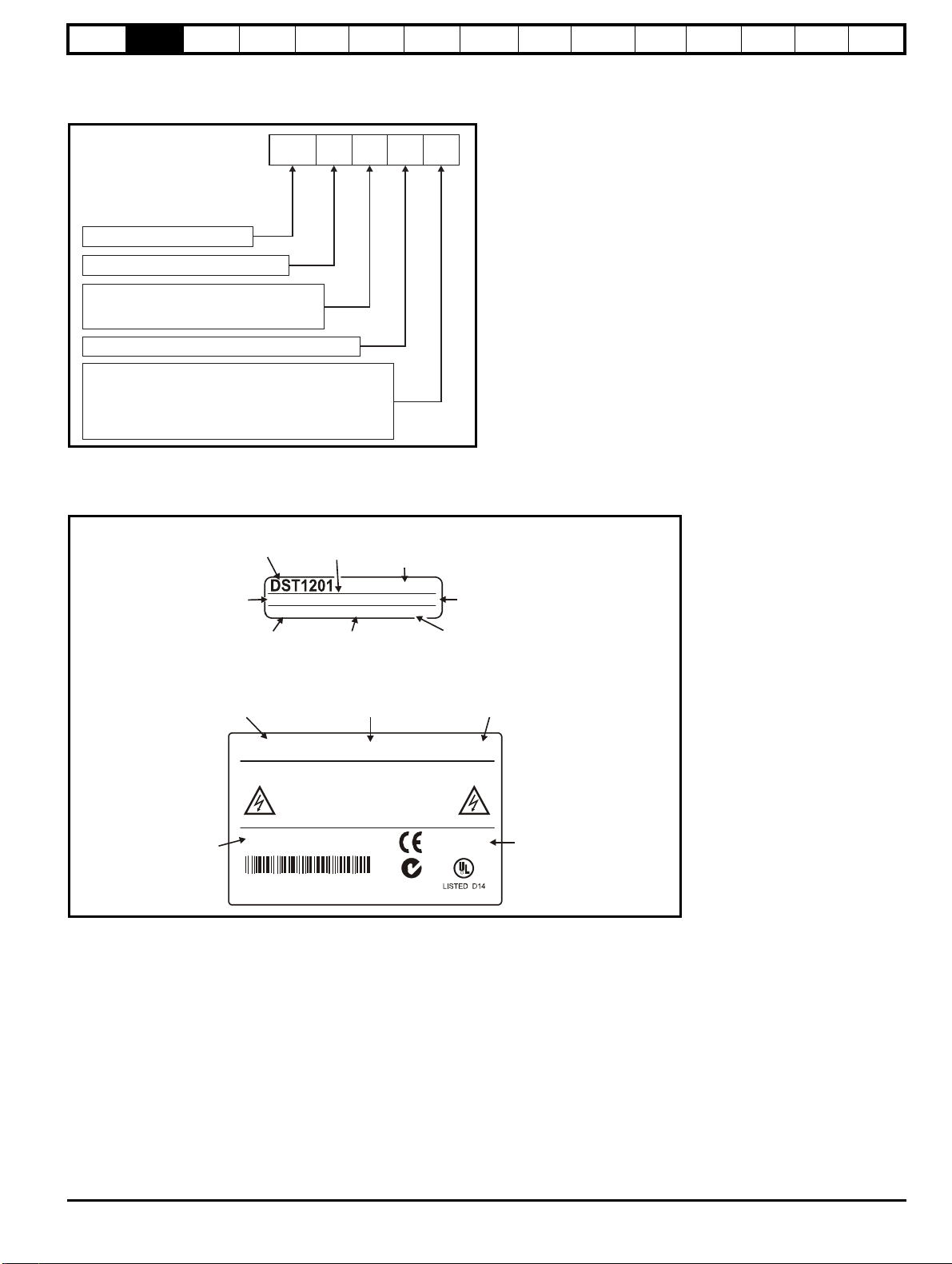
Model: Digitax ST
Frame size
Voltage rating
2:4:200V to 240V
380V to 480V
Current rating step
Variant
DST 1 2 01 B
B:
I:
P:
Z:
E:
Base
Indexer
Plus
EZMotion
EtherCAT
Model
3098-0010
2.2/5.1Apk 250ms
S/N: 3000005001
Serial
number
Rating
Please read the manual before connecting
Electric Shock Risk: Wait 10 mins
between disconnecting supply
and accessing terminals
UL file: E171230
Approvals
Approvals label
Designed in the U.K. Made in China
IND. CONTROL
EQUIPMENT
R
RoHS
Compliant
I/P 200-240V 50-60Hz 1/3ph 4.0/3.1A
O/P 0-240V 2.2/5.1Apk
Input
voltage
CT Model type
Serial
number
Single/three phase
peak output current
Output voltage
ST 1.1A M/TL 3ph
Rating label
S/N: 3000005001
Single/three
phase input
current
Frequency
LS Model
type
CUS
8
R10
Date code
N1652
Information
Product
information
Mechanical
installation
Electrical
installation
Getting
started
Basic
parameters
Running the
motor
Optimization
EtherCAT
interface
SMARTCARD
Operation
2.3 Drive model numbers
Each drive variant and rating has a unique model number.
Figure 2-1 Model code explanation
2.4 Drive nameplate description
The drive rating label provides the user with various details relating to the drive variant and rating.
Figure 2-2 Typical drive label
Onboard
PLC
Advanced
parameters
Technical
Data
Diagnostics
UL listing
information
Digitax ST User Guide 9
Issue: 5
Safety
Solutions
Module
slot 2
cover
Solutions
Module
slot 1
cover
Buffered
encoder output
Encoder In
connection
Motor
connections
Line to
ground
varistor
screw
AC supply
48V connection
(for low voltage
DC operation)
Braking
resistor
connections
SMARTCARD
slot
Serial port
connector
Control
terminals
Relay
terminal
Keypad
connection
EMC bracket
Ground
screw
EMC bracket
Ground
screw
Status LED
Marker tag
location
*
Internal
EMC
filter
screw
Rating
label
Approvals
label
Brake
resistor slot
Reset
button
**
Fan
Control cable
strain relief
Product
identifier
NOTE
NOTE
WARNING
CAUTION
Information
Product
information
Mechanical
installation
Electrical
installation
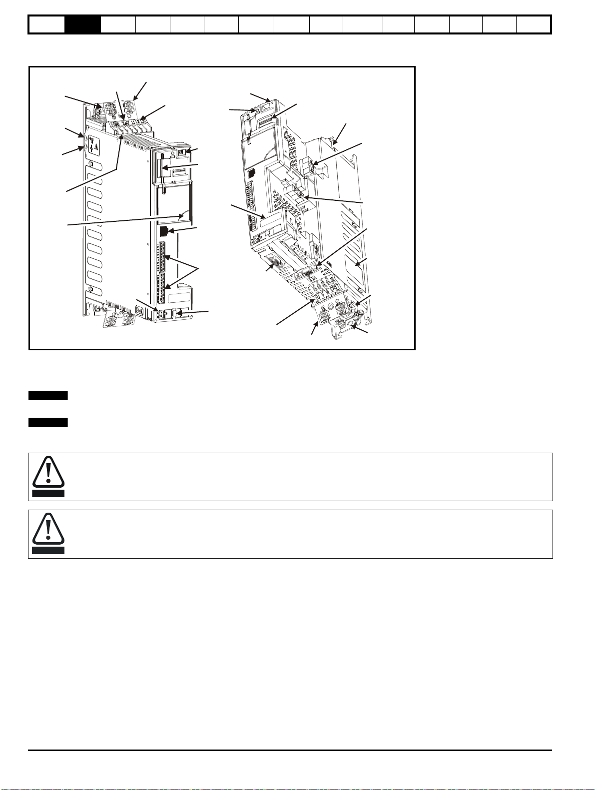
2.5 Features of the drive
Figure 2-3 Features of the drive
Getting
started
Basic
parameters
Running the
motor
Optimization
EtherCAT
interface
SMARTCARD
Operation
Onboard
PLC
Advanced
parameters
Technical
Data
Diagnostics
UL listing
information
*
The Marker Tag (as shown in Figure 2-3 above), is where markers can be placed to identify a particular drive which can prove beneficial where several Digitax
ST drives are located in the same panel.
** A drive reset can be performed even when a keypad is not installed, by pressing the recessed reset button.
If the embedded interface is removed, the warranty for the drive will be void.
The drive is supplied with a SMARTCARD installed. Do not remove until after first power-up, as defaults are stored on the SMARTCARD.
Be aware of possible live terminals when inserting the SMARTCARD.
Static precautions must be taken when removing the Solutions Module slot covers.
10 Digitax ST User Guide
Issue: 5
Safety
SM-Keypad Plus
SMARTCARD*
DST Keypad
CT Comms
cable
External footprint/
bookcase EMC
filter
Internal
braking
resistor
Grounding
bracket
15-way
D-type
converter
I/O Expansion
Applications
Automation
Fieldbus
Feedback
S
l
o
t
2
S
l
o
t
1
*
Inputs Outputs
• Incremental encoders • Quadrature
• SinCos encoders • Frequency and direction
• SSI encoders • SSI simulated outputs
• EnDat encoders
Information
Product
information
Mechanical
installation
Electrical
installation
Getting
started
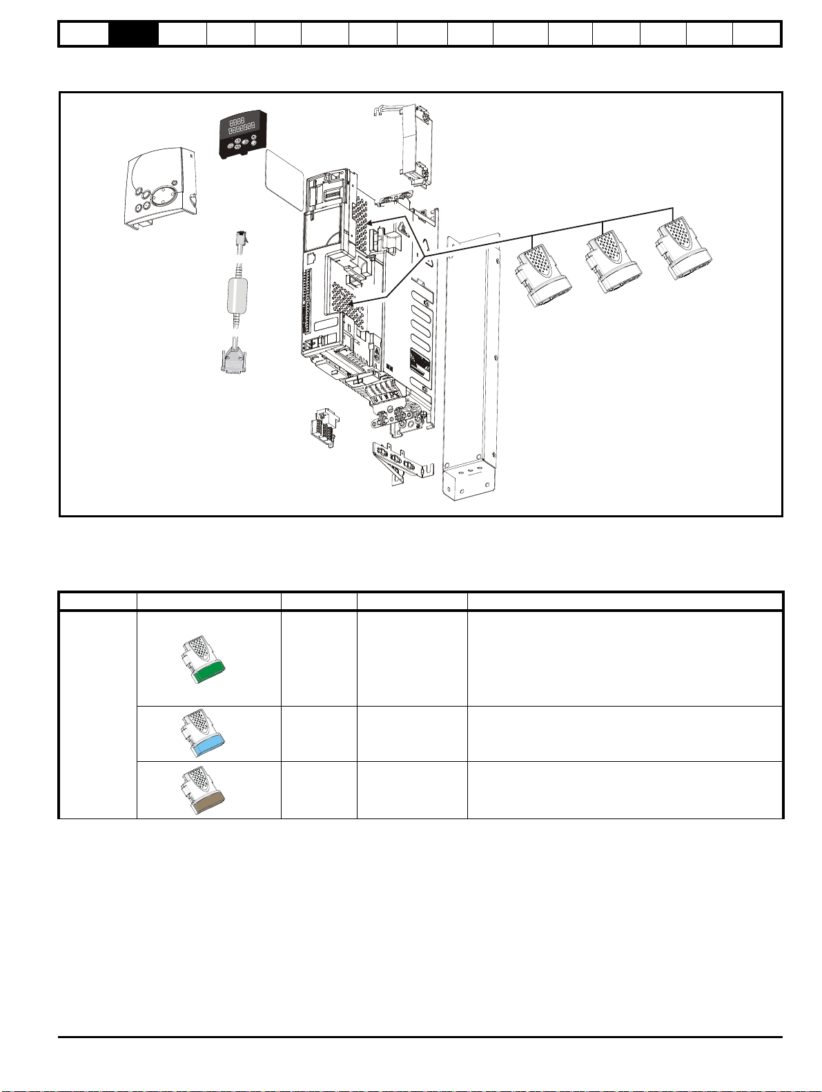
2.6 Options
Figure 2-4 Options available with Digitax ST
Basic
parameters
Running the
motor
Optimization
EtherCAT
interface
SMARTCARD
Operation
Onboard
PLC
Advanced
parameters
Technical
Data
Diagnostics
UL listing
information
* A SMARTCARD is provided as standard. For further information refer to Chapter 10 SMARTCARD Operation on page 101.
All Solutions Modules are color-coded in order to make identification easy. The following table shows the color-code key and gives further details on
their function.
Table 2-2 Solutions Module identification
Type Solutions Module Color Name Further Details
Universal Feedback interface
Feedback interface for the following devices:
SM-Universal
Encoder Plus
Resolver interface
Feedback interface for resolvers.
Simulated quadrature encoder outputs
Feedback
Light Green
Light Blue SM-Resolver
Incremental encoder interface
Brown SM-Encoder Plus
Feedback interface for incremental encoders without
commutation signals.
No simulated encoder outputs available
Digitax ST User Guide 11
Issue: 5
Safety
• Digital inputs x 3
• Analog output (voltage) x 1
• Digital I/O x 3 • Relay x 2
• Analog inputs (voltage) x 2
Information
Product
information
Mechanical
installation
Electrical
installation
Getting
started
Basic
parameters
Running the
motor
Optimization
EtherCAT
interface
SMARTCARD
Operation
Onboard
PLC
Advanced
parameters
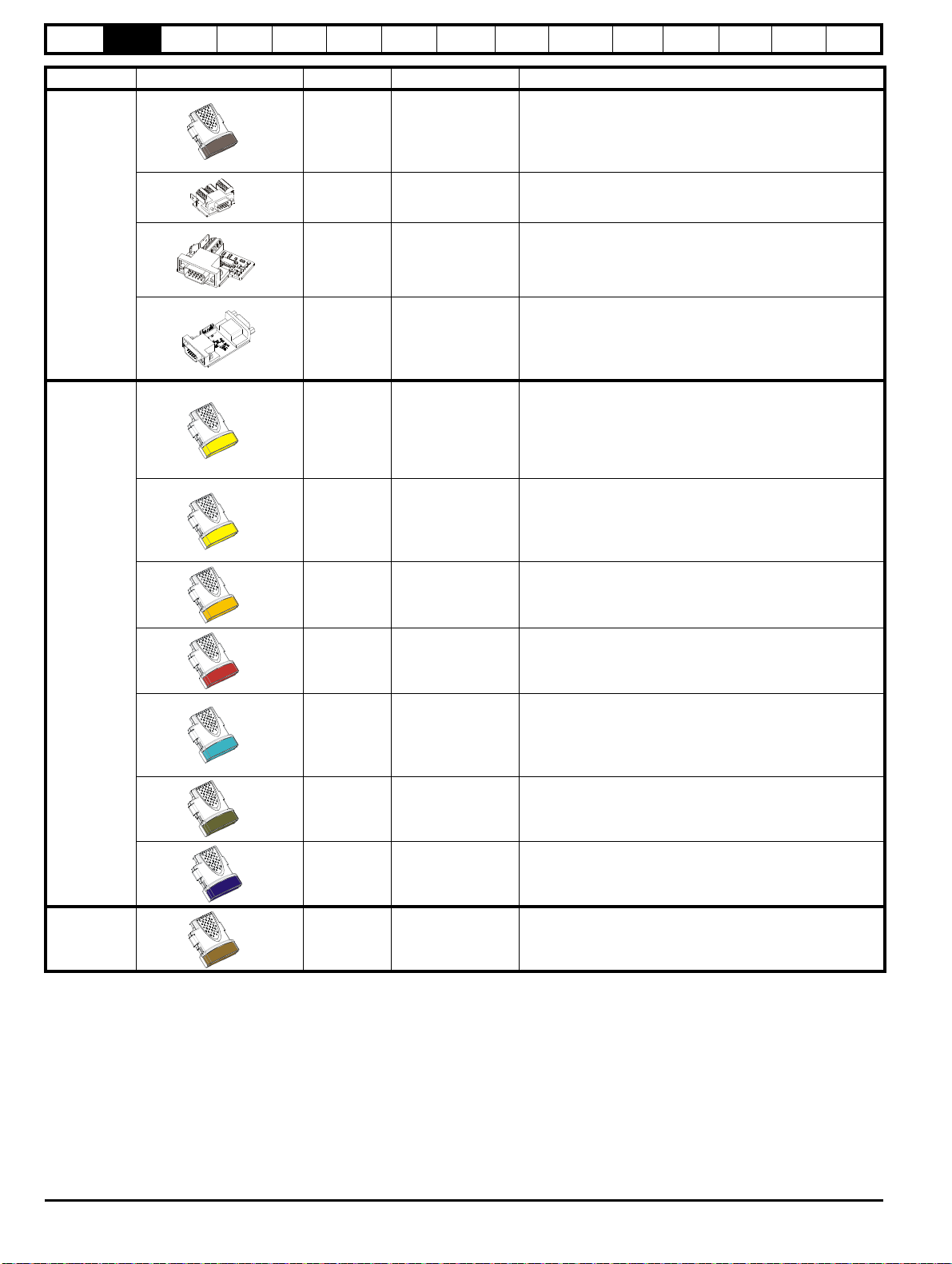
Type Solutions Module Color Name Further Details
Incremental encoder interface
Feedback interface for incremental encoders without
commutation signals.
Simulated encoder output for quadrature, frequency and
Dark Brown
SM-Encoder Output
Plus
direction signals
Drive encoder input converter
Provides screw terminal interface for encoder wiring and spade
terminal for shield
Single ended encoder interface
Provides an interface for single ended ABZ or UVW encoder
signals, such as those from hall effect sensors. 15 V and 24 V
versions are available.
Feedback
N/A
N/A
15-way D-type
converter
Single ended
encoder interface
(15 V or 24 V)
ERN1387 Encoder Interface Board
Provides an interface for Heidenhain ERN1387 and ERN487
SinCos encoder which use a single SinCos cycle per revolution
commutation track. A SM-Universal Encoder Plus module is
N/A
ERN1387 Encoder
Interface Board
required to use this interface board.
Extended I/O interface
Increases the I/O capability by adding the following to the
Yellow SM-I/O Plus
existing I/O in the drive:
Extended I/O interface
Increase the I/O capability by adding the following to the
Yellow SM-I/O 32
existing I/O in the drive:
• High speed digital I/O x 32
• +24 V output
Additional I/O
1 x Analog input (±10 V bi-polar or current modes)
1 x Analog output (0-10 V or current modes)
3 x Digital input and 1 x Relay
Additional I/O with real time clock
As per SM-I/O Lite but with the addition of a Real Time Clock
Automation
(I/O
Expansion)
Dark Yellow SM-I/O Lite
Dark Red SM-I/O Timer
for scheduling drive running
Isolated I/O to NAMUR NE37 specifications
For chemical industry applications
Turquoise SM-I/O PELV
1 x Analog input (current modes)
2 x Analog outputs (current modes)
4 x Digital input / outputs, 1 x Digital input, 2 x Relay outputs
Technical
Data
Diagnostics
UL listing
information
Olive SM-I/O 120V
Cobalt Blue
Automation
(Applications)
12 Digitax ST User Guide
Golden
brown
SM-I/O 24V
Protected
SM-Register
Additional I/O conforming to IEC 61131-2 120 Vac
6 digital inputs and 2 relay outputs rated for 120 Vac operation
Additional I/O with overvoltage protection up to 48 V
2 x Analog outputs (current modes)
4 x Digital input / outputs, 3 x Digital inputs, 2 x Relay outputs
Applications Processor
nd
2
processor for running position capture functionality with
CTNet support.
Issue: 5
Safety
Information
Product
information
Mechanical
installation
Electrical
installation
Getting
started
Basic
parameters
Running the
motor
Optimization
EtherCAT
interface
SMARTCARD
Operation
Onboard
PLC
Advanced
parameters
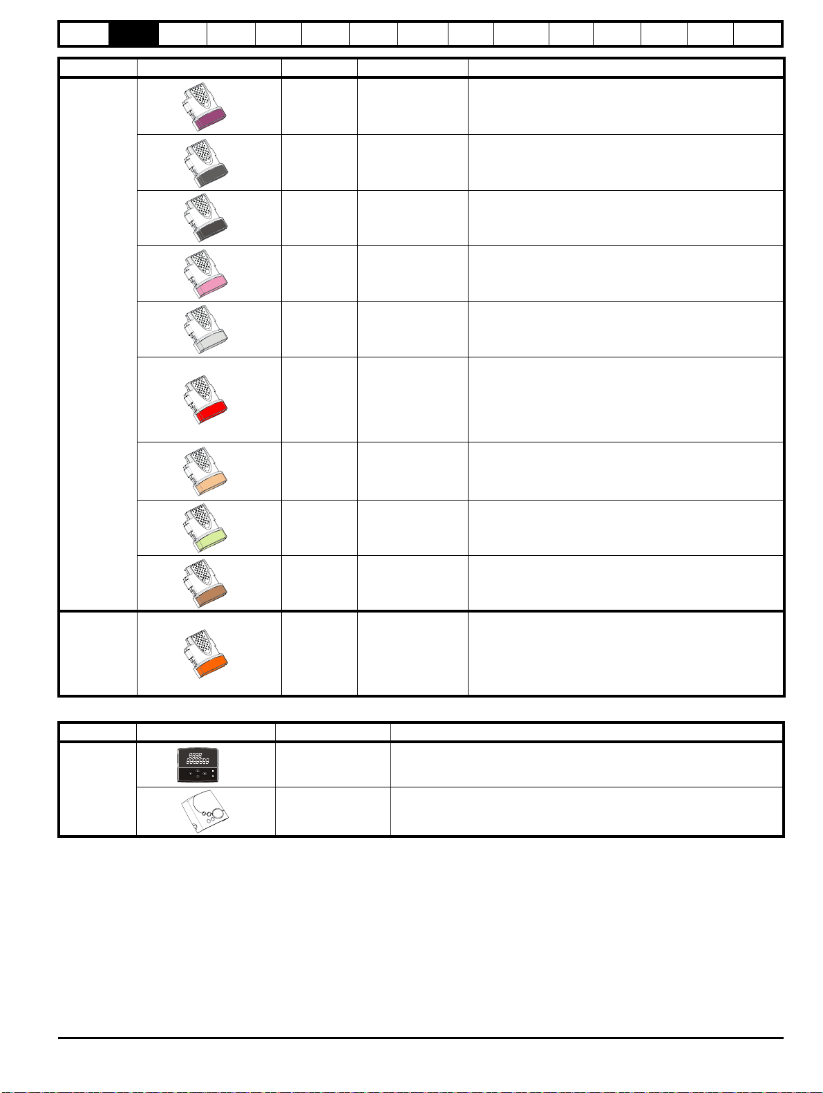
Type Solutions Module Color Name Further Details
Technical
Data
Diagnostics
UL listing
information
Fieldbus
Purple
SM-PROFIBUS-DP-V1Profibus option
Medium Grey SM-DeviceNet
Dark Grey SM-INTERBUS
Pink SM-CAN
Light Grey SM-CANopen
Red SM-SERCOS
Beige SM-Ethernet
PROFIBUS DP adapter for communications with the drive
DeviceNet option
Devicenet adapter for communications with the drive
Interbus option
Interbus adapter for communications with the drive
CAN option
CAN adapter for communications with the drive
CANopen option
CANopen adapter for communications with the drive
SERCOS option
Class B compliant. Torque velocity and position control modes
supported with data rates (bit/sec): 2 MB, 4 MB, 8 MB and 16
MB.
Minimum 250 μsec network cycle time. Two digital high speed
probe inputs 1 μsec for position capture
Ethernet option
10 base-T / 100 base-T; Supports web pages, SMTP mail and
multiple protocols: DHCP IP addressing; Standard RJ45
connection
Pale Green SM-LON
Brown Red SM-EtherCAT
LonWorks option
LonWorks adapter for communications with the drive
EtherCAT option
EtherCAT adapter for communications with the drive
SLM interface
The SM-SLM allows SLM feedback to be connected directly to
SLM Orange SM-SLM
the Digitax ST drive and allows operation in either of the
following modes:
• Encoder only mode
• Host mode
Table 2-3 Keypad identification
Type Keypad Name Further Details
Digitax ST Keypad
LED keypad option
Keypad with a LED display
Keypad
SM-Keypad Plus
Remote keypad option
Keypad with an alpha-numeric LCD display with Help function
Digitax ST User Guide 13
Issue: 5
Safety
Control
connectors
Relay
connector
Ground
screws
Cable
guides
Grounding
bracket
Ground
screws
Digitax ST
Plus
additional
connectors
123
Digitax ST
EtherCAT
additional
connector
Information
Product
information
Mechanical
installation
Electrical
installation
Getting
started
Basic
parameters
Running the
motor
Optimization
EtherCAT
interface
SMARTCARD
Operation
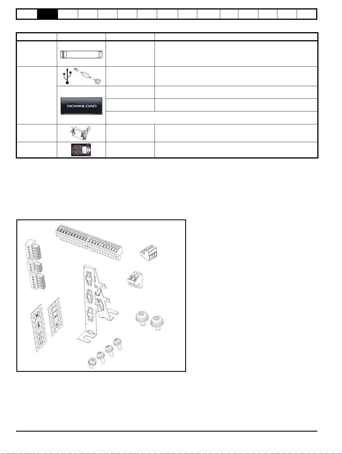
Table 2-4 Other options
Type Option Name Further details
Onboard
PLC
Advanced
parameters
Technical
Data
Diagnostics
UL listing
information
EMC EMC Filters
CT Comms cable
Communications
CTSoft
SyPTLite
These additional filters are designed to operate together with the drive’s own
integral EMC filter in areas of sensitive equipment
Cable with isolation RS232 to RS485 converter. For connecting PC/Laptop to
the drive when using the various interface software (e.g. CTSoft)
Software for PC or Laptop which allows the user to commission and store
parameter settings.
Software for PC or Laptop which allows the user to program PLC functions
within the drive.
Both CTSoft and SyPTLite can be downloaded at: http://www.emersonindustrial.com/en-EN/
controltechniques/downloads/userguidesandsoftware/Pages/digitaxst.aspx
Internal braking
resistor
SMARTCARD SMARTCARD
Braking resistor Optional braking resistor 70R 50 W
Standard feature that enables simple configuration of parameters in a variety of
ways
2.7 Items supplied with the drive
The drive is supplied with the following items:
• Installation Guide
•SMARTCARD
• Safety Information booklet
• Certificate of Quality
An accessory box containing the items illustrated in Figure 2-5 is also provided.
Figure 2-5 Accessory box contents
Issue: 5
14 Digitax ST User Guide
Safety
WARNING
WARNING
WARNING
WARNING
NOTE
Drive
5
o
Information
Product
information
Mechanical
installation
Electrical
installation
Getting
started
Basic
parameters
Running the
motor
Optimization
3 Mechanical installation
This chapter describes how to use all mechanical details to install the
drive. The drive is intended to be installed in an enclosure. Key features
of this chapter include:
• Through-hole mounting
• IP54 as standard or through-panel mounting
• Enclosure sizing and layout
• Solutions Module installing
• Terminal location and torque settings
3.1 Safety information
Follow the instructions
The mechanical and electrical installation instructions must
be adhered to. Any questions or doubt should be referred to
the supplier of the equipment. It is the responsibility of the
owner or user to ensure that the installation of the drive and
any external option unit, and the way in which they are
operated and maintained, comply with the requirements of
the Health and Safety at Work Act in the United Kingdom or
applicable legislation and regulations and codes of practice in
the country in which the equipment is used.
Stored charge
The drive contains capacitors that remain charged to a
potentially lethal voltage after the AC supply has been
disconnected. If the drive has been energized, the AC
supply must be isolated at least ten minutes before work
may continue. Normally, the capacitors are discharged by an
internal resistor. Under certain, unusual fault conditions, it is
possible that the capacitors may fail to discharge, or be
prevented from being discharged by a voltage applied to the
output terminals. If the drive has failed in a manner that
causes the display to go blank immediately, it is possible the
capacitors will not be discharged. In this case, consult
Emerson Industrial Automation or their authorized
distributor.
EtherCAT
interface
SMARTCARD
Operation
Onboard
PLC
Advanced
parameters
Technical
Data
Diagnostics
UL listing
information
• corrosive gasses
During installation it is recommended that the vents on the drive are
covered to prevent debris (e.g. wire off-cuts) from entering the drive.
3.2.3 Cooling
The heat produced by the drive must be removed without its specified
operating temperature being exceeded. Note that a sealed enclosure
gives much reduced cooling compared with a ventilated one, and may
need to be larger and/or use internal air circulating fans.
3.2.4 Electrical safety
The installation must be safe under normal and fault conditions.
Electrical installation instructions are given in Chapter 4 Electrical
installation on page 21.
3.2.5 Fire protection
The drive enclosure is not classified as a fire enclosure. A separate fire
enclosure must be provided.
For installation in the USA, a NEMA 12 enclosure is suitable.
For installation outside the USA, the following (based on IEC 62109-1,
standard for PV inverters) is recommended.
Enclosure can be metal and/or polymeric, polymer must meet
requirements which can be summarized for larger enclosures as using
materials meeting at least UL 94 class 5VB at the point of minimum
thickness.
Air filter assemblies to be at least class V-2.
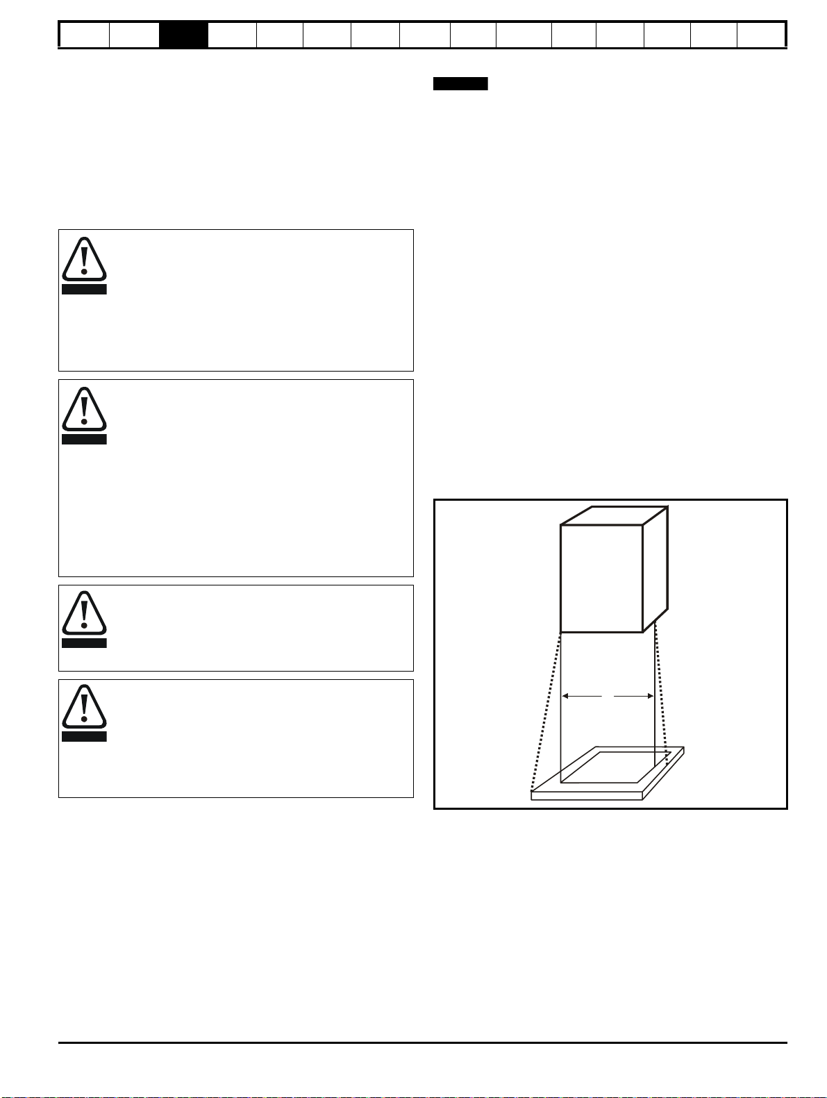
The location and size of the bottom shall cover the area shown in Figure
3-1. Any part of the side which is within the area traced out by the 5°
angle is also considered to be part of the bottom of the fire enclosure.
Figure 3-1 Fire enclosure bottom layout
Competence of the installer
The drive must be installed by professional assemblers who
are familiar with the requirements for safety and EMC. The
assembler is responsible for ensuring that the end product or
system complies with all the relevant laws in the country
where it is to be used.
Enclosure
The drive is intended to be mounted in an enclosure which
prevents access except by trained and authorized
personnel, and which prevents the ingress of contamination.
It is designed for use in an environment classified as
pollution degree 2 in accordance with IEC 60664-1. This
means that only dry, non-conducting contamination is
acceptable.
3.2 Planning the installation
The following considerations must be made when planning the installation:
3.2.1 Access
Access must be restricted to authorized personnel only. Safety
regulations which apply at the place of use must be complied with.
3.2.2 Environmental protection
The drive must be protected from:
• moisture, including dripping water or spraying water and
condensation. An anti-condensation heater may be required, which
must be switched off when the drive is running.
• contamination with electrically conductive material
• contamination with any form of dust which may restrict the fan, or
impair airflow over various components
• temperature beyond the specified operating and storage ranges
The bottom, including the part of the side considered to be part of the
bottom, must be designed to prevent escape of burning material - either
by having no openings or by having a baffle construction. This means
that openings for cables etc. must be sealed with materials meeting the
5VB requirement, or else have a baffle above. See Figure 3-2 for
acceptable baffle construction. This does not apply for mounting in an
enclosed electrical operating area (restricted access) with concrete floor.
Digitax ST User Guide 15
Issue: 5
Safety
Notless
than 2X
Ba ffle plates (m ay be
above orbelow bottom
ofenclosure)
X
Bo ttom of fire
enclosure
Not less
than 2
times ‘X’
Baffle plates (may be above or
below bottom of enclosure)
Bottom of fire enclosure
X
CAUTION
NOTE
WARNING
Information
information
Product
Mechanical
installation
Electrical
installation
Getting
started
Basic
parameters
Running the
motor
Optimization
Figure 3-2 Fire enclosure baffle construction
3.2.6 Electromagnetic compatibility
Variable speed drives are powerful electronic circuits which can cause
electromagnetic interference if not installed correctly with careful
attention to the layout of the wiring.
Some simple routine precautions can prevent disturbance to typical
industrial control equipment.
If it is necessary to meet strict emission limits, or if it is known that
electromagnetically sensitive equipment is located nearby, then full
precautions must be observed. In-built into the drive, is an internal EMC
filter, which reduces emissions under certain conditions. If these
conditions are exceeded, then the use of an external EMC filter may be
required at the drive inputs, which must be located very close to the
drives. Space must be made available for the filters and allowance made
for carefully segregated wiring. Both levels of precautions are covered in
section 4.10 EMC (Electromagnetic compatibility) on page 28.
3.2.7 Hazardous areas
The drive must not be located in a classified hazardous area unless it is
installed in an approved enclosure and the installation is certified.
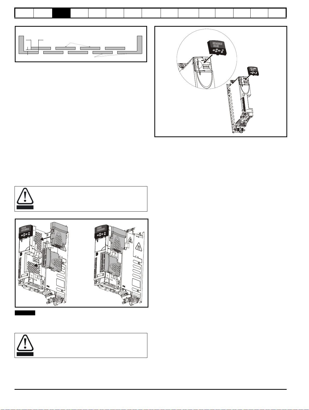
3.3 Solutions Module / keypad installation
/ removal
EtherCAT
interface
SMARTCARD
Operation
Onboard
PLC
Advanced
parameters
Figure 3-4 Installation of a keypad
Technical
Data
Diagnostics
UL listing
information
Power down the drive before installing / removing the
Solutions Module. Failure to do so may result in damage to
the product.
Figure 3-3 Installation of a Solutions Module
The protective tab from the Solutions Module slot must be removed
before attempting to install a Solutions Module.
Be aware of possible live terminals when installing the
keypad.
16 Digitax ST User Guide
Issue: 5
Safety
WARNING
62mm
(2.44in)
249.7mm
(9.83in)
220mm (8.66in)
47mm
(1.85in)
7.5mm
(0.3in)
304mm
(11.96in)
292mm
(11.49in)
6mm
(0.24in)
∅
5.4mm (0.21in)
M5
322mm
(12.68in)
226mm (8.9in)
226mm (8.9in)
229mm (9.02in)
Ingress protective labels
NOTE
100mm (4in)
100mm (4in)
*2mm (0.08in)
NOTE
Information
Product
information
Mechanical
installation
Electrical
installation
Getting
started
Basic
parameters
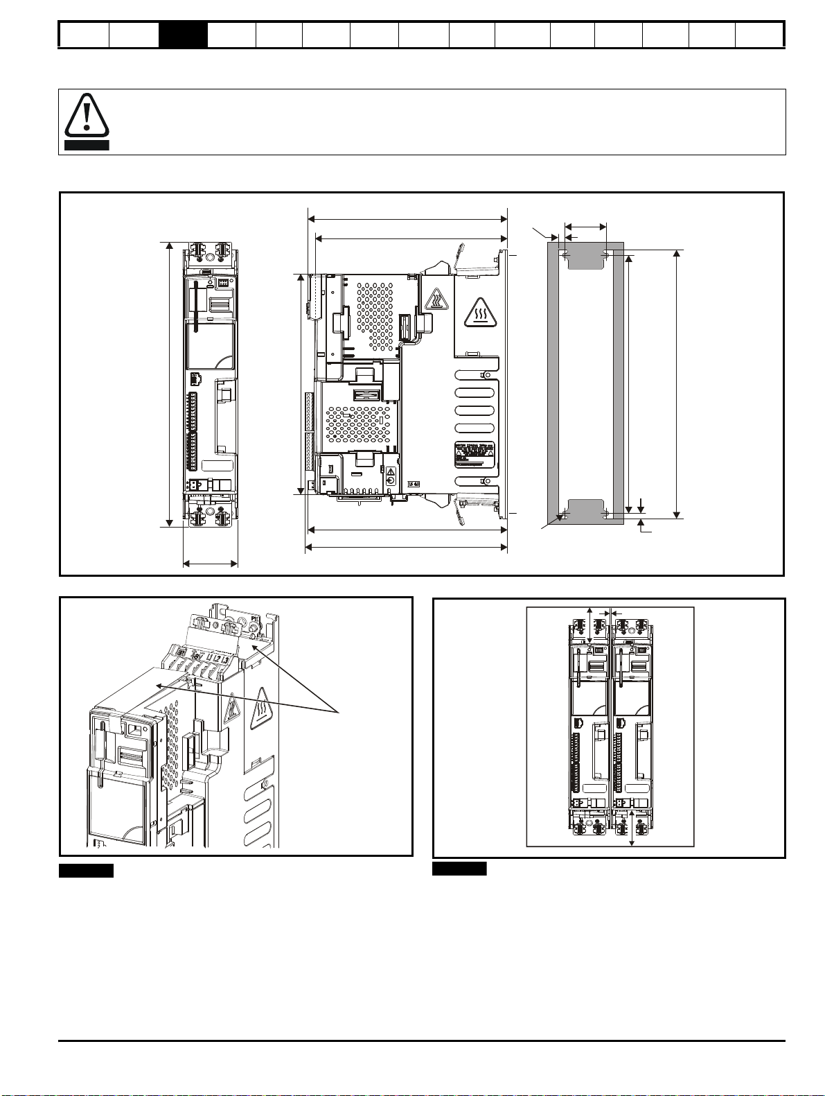
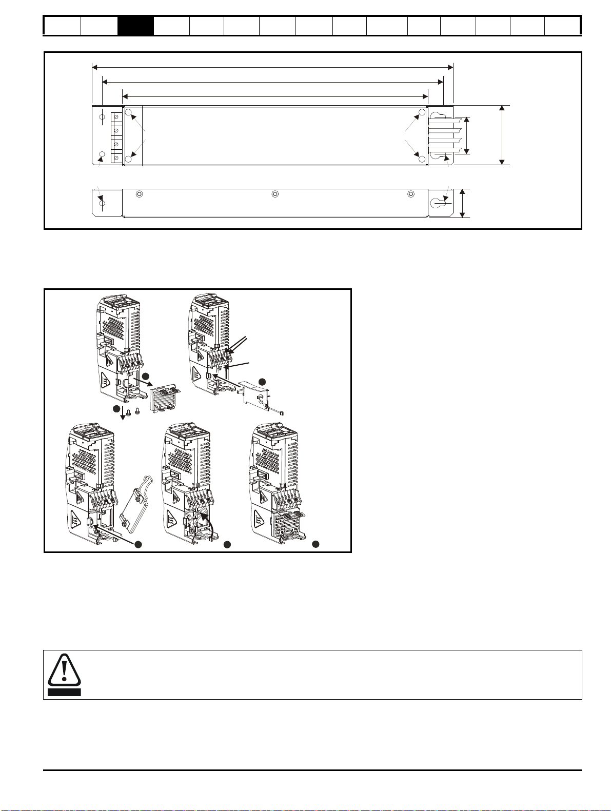
3.4 Drive dimensions
Enclosure
The drive is intended to be mounted in an enclosure which prevents access except by trained and authorized personnel, and which
prevents the ingress of contamination. It is designed for use in an environment classified as pollution degree 2 in accordance with IEC
60664-1. This means that only dry, non-conducting contamination is acceptable.
The drive complies with the requirements of IP20 as standard.
Figure 3-5 Dimensions
Running the
motor
Optimization
EtherCAT
interface
SMARTCARD
Operation
Onboard
PLC
Advanced
parameters
Technical
Data
Diagnostics
UL listing
information
Figure 3-6 Ingress protective label
The ingress protective labels (shown on Figure 3-6 above) should
remain in place while the drive is mounted, and until all the electrical
wires have been connected. The labels should be removed before first
power up.
Figure 3-7 Minimum mounting clearances
*2 mm clearance between drives to allow for mechanical tolerance.
If Solutions Modules are installed, a larger clearance between drives will
be required if access to the modules is needed without removing the
drive.
Digitax ST User Guide 17
Issue: 5
Safety
47mm (1.85in)
312.7mm
(12.31in)
Information
information
Product
Mechanical
installation
Electrical
installation
Getting
started
Basic
parameters
Running the
motor
Optimization
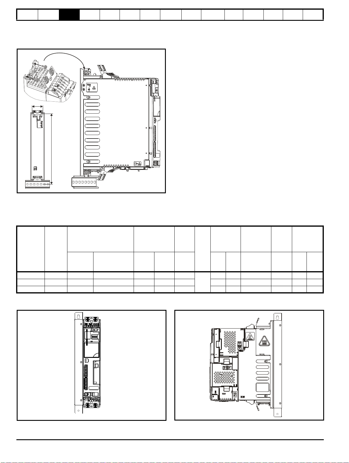
Digitax ST can be mounted using a DIN rail, either fixed at the top or the
bottom of the drive (as illustrated in Figure ). Two screws are required to
fix the drive to the backplate at the opposite end to the DIN rail.
Figure 3-8 DIN rail mounting
EtherCAT
interface
SMARTCARD
Operation
Onboard
PLC
Advanced
parameters
Technical
Data
Diagnostics
UL listing
information
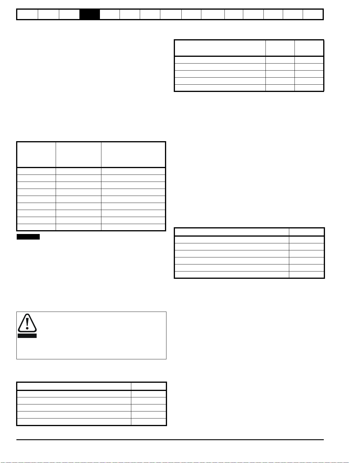
3.5 External EMC filter rating
Filter details for each drive rating are provided in the tables below.
Table 3-1 External EMC filter ratings
Worst
case
leakage
current
Used with
Number
of
phases
Filter part number
CT Schaffner
Maximum
continuous
current
@40°C
(104°F)
@50°C
Power
losses
at rated
current
Weight
IP
rating
Operational
leakage
current
(122°F)AWKglbmAmANmlb ft
A
DST120X 1 4200-6000 FS23072-19-07 19 17.3 11
DST120X 3 4200-6001 FS23073-17-07 17 15.5 13 1.2 2.64 8 50 0.8 0.6
1.2 2.64 29.5 56.9 0.8 0.6
20
DST140X 3 4200-6002 FS23074-11-07 11 10 10 1.2 2.64 16 90 0.8 0.6
The external EMC filters can be footprint or bookcase mounted, see Figure 3-9 and Figure 3-10.
Figure 3-9 Bookcase mounting Figure 3-10 Footprint mounting
Filter
terminal
tightening
torque
18 Digitax ST User Guide
Issue: 5
Safety
29mm (1.14in)
359mm (14.13in)
339mm (13.35in)
304mm (11.97in)
38mm
(1.50in)
61mm
(2.40in)
M5 M5
Torque settings of connector = 0.8 N m
∅
5.3mm (M5)
(0.21in)
∅
5.3mm (M5)
(0.21in)
4
2
1
Brake
connections
Thermistor
connection
3
5
6
WARNING
Information
Product
information
Mechanical
installation
Electrical
installation
Getting
started
Basic
parameters
Running the
motor
Optimization
EtherCAT
interface
SMARTCARD
Operation
Onboard
PLC
Advanced
parameters
Technical
Data
Diagnostics
UL listing
information
Figure 3-11 External EMC filter dimensions
Figure 3-11 shows a 3 phase filter. For a single phase filter, there are only 3 input terminals (L1, N, ground) and 3 output cables (L1, N, ground).
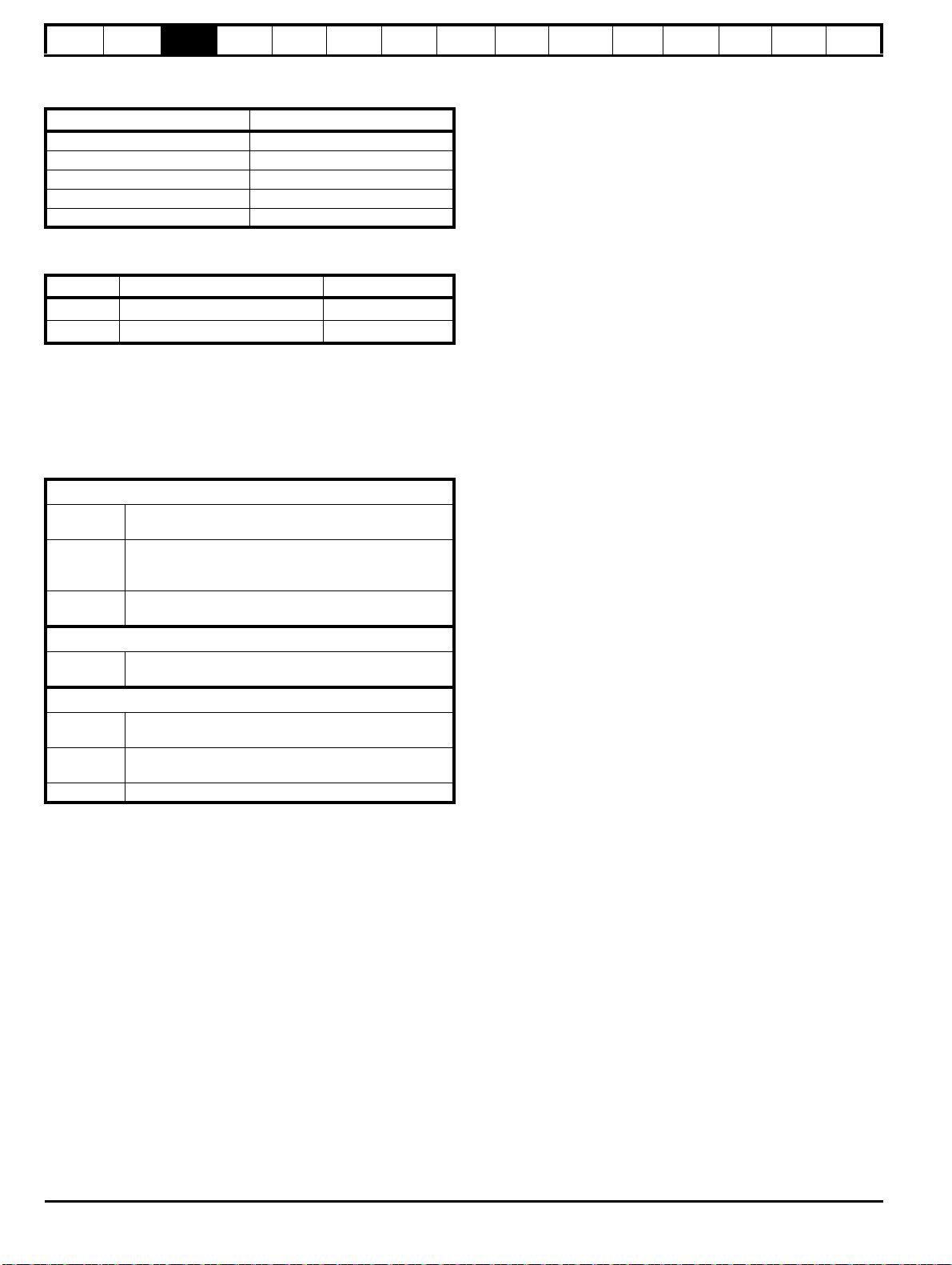
3.6 Optional braking resistor
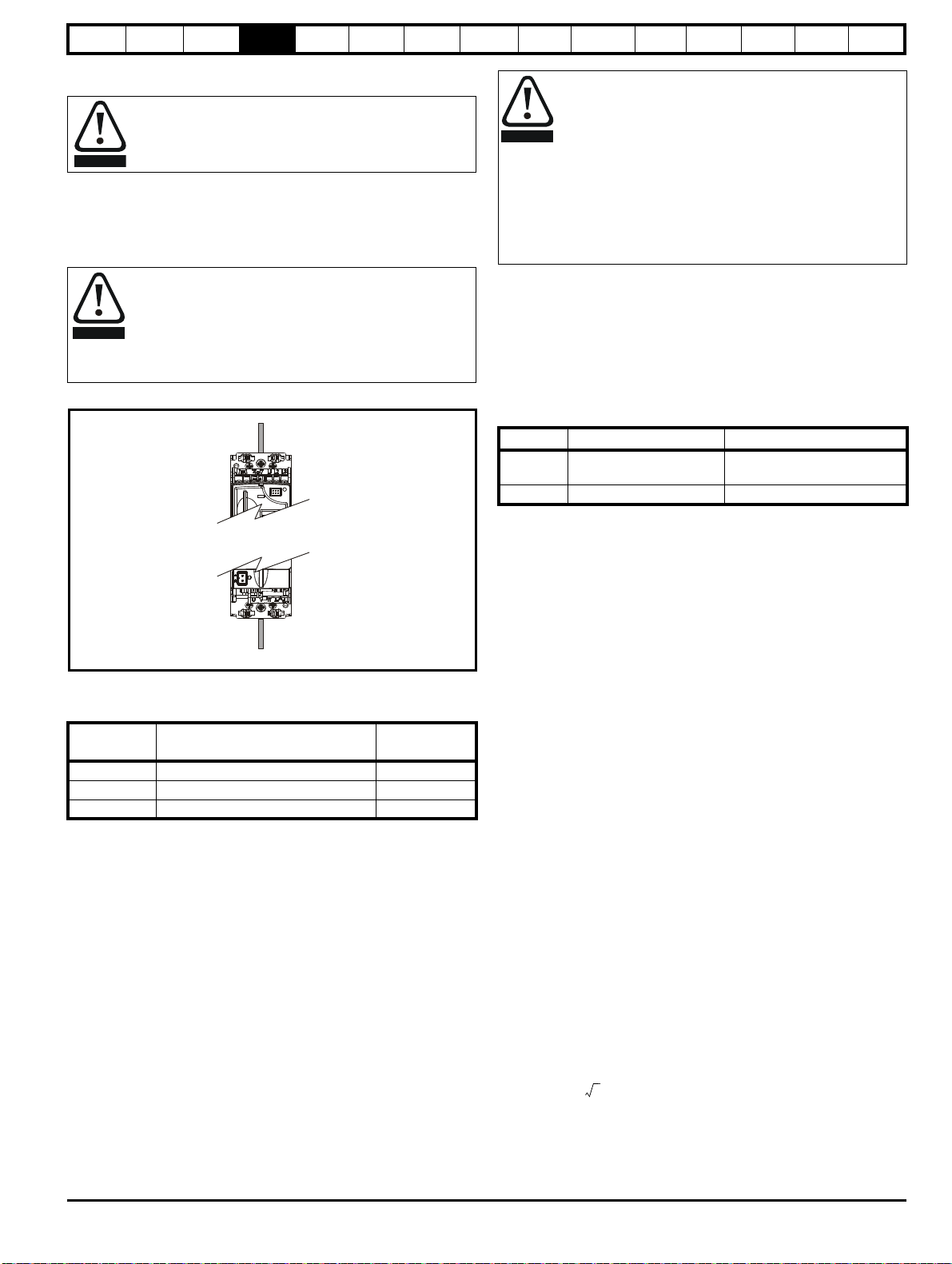
3.6.1 Optional internal braking resistor
Figure 3-12 Installing an optional internal braking resistor (top view of drive)
1. Remove screws.
2. Remove grill.
3. Install the braking resistor shield.
4. Install the optional internal braking resistor in the slot provided (note the angle).
5. Electrically connect the braking resistor and thermistor (connections shown in Figure 4-1 Power terminal connections on page 22).
6. Re-install the grill and mounting screws by reversing the procedure in points 1 and 2.
3.6.2 Optional external braking resistor
If using an external braking resistor, the following Warning must be adhered to:
Digitax ST User Guide 19
Issue: 5
Braking resistor: High temperatures and overload protection
Braking resistors can reach high temperatures. Locate braking resistors so that damage cannot result. Use cable having insulation capable
of withstanding the high temperatures.
Safety
Information
information
Product
Mechanical
installation
Electrical
installation
Getting
started
Basic
parameters
Running the
motor
3.7 Terminal torque settings
Table 3-2 Torque settings
Terminals Torque setting*
Power terminals 1.0 N m (12.1 lb in)
Control terminals 0.2 N m (1.7 lb in)
Status relay terminals 0.5 N m (4.5 lb in)
Ground terminals 4 N m (35 lb in)
Small ground terminal screws 2 N m (17.7 lb in)
*Torque tolerance = 10 %
Table 3-3 Plug-in terminal block maximum cable sizes
Model size Terminal block description Max cable size
All 11 way control connectors
All 2 way relay connector
1.5 mm
2.5 mm
2
(16 AWG)
2
(12 AWG)
3.8 Routine maintenance
The drive should be installed in a cool, clean, well ventilated location.
Contact of moisture and dust with the drive should be prevented.
Regular checks of the following should be carried out to ensure drive /
installation reliability are maximized:
Environment
Ambient
temperature
Dust
Moisture
Enclosure
Enclosure
door filters
Electrical
Screw
connections
Crimp
terminals
Cables Check all cables for signs of damage
Ensure the enclosure temperature remains at or below
maximum specified
Ensure the drive remains dust free – check that the
heatsink and drive fan are not gathering dust. The
lifetime of the fan is reduced in dusty environments.
Ensure the drive enclosure shows no signs of
condensation
Ensure filters are not blocked and that air is free to flow
Ensure all screw terminals remain tight
Ensure all crimp terminals remains tight – check for any
discoloration which could indicate overheating
Optimization
EtherCAT
interface
SMARTCARD
Operation
Onboard
PLC
Advanced
parameters
Technical
Data
Diagnostics
UL listing
information
20 Digitax ST User Guide
Issue: 5
Safety
WARNING
WARNING
WARNING
WARNING
WARNING
WARNING
WARNING
Information
Product
information
Mechanical
installation
Electrical
installation
Getting
started
Basic
parameters
Running the
motor
Optimization
4 Electrical installation
Many cable management features have been incorporated into the
product and accessories, this chapter shows how to optimize them. Key
features include:
• Safe Torque Off function
• Internal EMC filter
• EMC compliance with shielding / grounding accessories
• Product rating, fusing and cabling information
• Brake resistor details (selection / ratings)
Electric shock risk
The voltages present in the following locations can cause
severe electric shock and may be lethal:
• AC supply cables and connections
• DC and brake cables, and connections
• Output cables and connections
• Many internal parts of the drive, and external option units
Unless otherwise indicated, control terminals are single
insulated and must not be touched.
Isolation device
The AC supply must be disconnected from the drive using
an approved isolation device before any cover is removed
from the drive or before any servicing work is performed.
EtherCAT
interface
SMARTCARD
Operation
Onboard
PLC
Advanced
parameters
Technical
Data
Diagnostics
UL listing
information
STOP function
The STOP function does not remove dangerous voltages
from the drive, the motor or any external option units.
Safe Torque Off function
The Safe Torque Off function does not remove dangerous
voltages from the drive, the motor or any external option
units.
Stored charge
The drive contains capacitors that remain charged to a
potentially lethal voltage after the AC supply has been
disconnected. If the drive has been energized, the AC
supply must be isolated at least ten minutes before work
may continue.
Normally, the capacitors are discharged by an internal
resistor. Under certain, unusual fault conditions, it is possible
that the capacitors may fail to discharge, or be prevented
from being discharged by a voltage applied to the output
terminals. If the drive has failed in a manner that causes the
display to go blank immediately, it is possible the capacitors
will not be discharged. In this case, consult Emerson
Industrial Automation or their authorized distributor.
Equipment supplied by plug and socket
Special attention must be given if the drive is installed in
equipment which is connected to the AC supply by a plug
and socket. The AC supply terminals of the drive are
connected to the internal capacitors through rectifier diodes
which are not intended to give safety isolation. If the plug
terminals can be touched when the plug is disconnected
from the socket, a means of automatically isolating the plug
from the drive must be used (e.g. a latching relay).
Permanent magnet motors
Permanent magnet motors generate electrical power if they
are rotated, even when the supply to the drive is
disconnected. If that happens then the drive will become
energized through its motor terminals.
If the motor load is capable of rotating the motor when the
supply is disconnected, then the motor must be isolated from
the drive before gaining access to any live parts.
Digitax ST User Guide 21
Issue: 5
Safety
L1*L2
*
L2L1L3/N
UVW
Optional EMC
filter
Optional
line reactor
Fuses
L3
*
Mains
supply
Supply
ground
AC
connections
_
+
DC
DC
High current
-DC connections
+
_
Low voltage
DC (48V)
DST12XX = 200 to 240V 10%
DST14XX = 380 to 480V 10%
±
±
Connectors specification:
Maximum size of power cable
= 4.0mm (10AWG)
Torque setting = 1 N m
2
PE
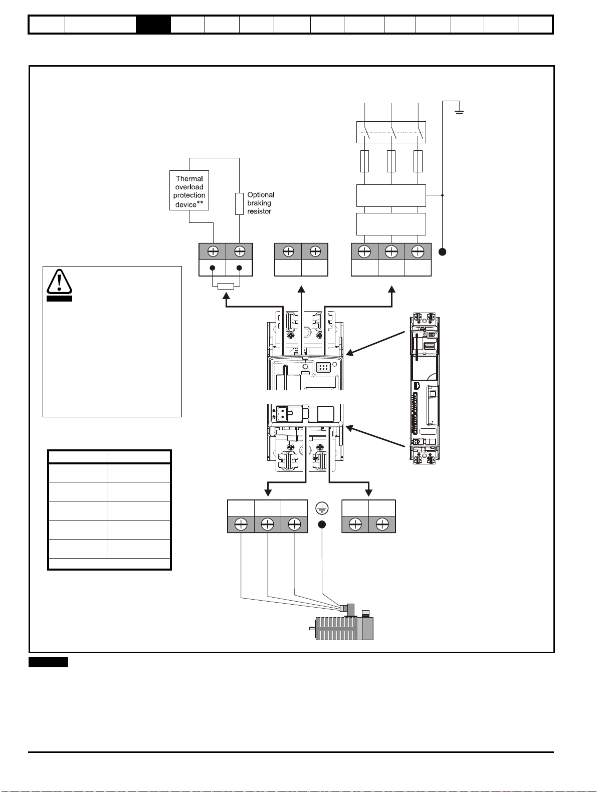
It is essential that the braking
resistor be protected against
overload caused by a failure
of the brake control. Unless
the resistor has in-built
protection, a circuit like those
shown in Figure 4-1 should
be used, where the thermal
protection device
disconnects the AC supply to
the drive. Do not use AC
relay contacts directly in
series with the braking
resistor circuit, because it
carries DC.
WARNING
Terminals Torque setting
Power terminals
1.0 N m
(12.1 lb in)
Control terminals
0.2 N m
(1.7 lb in)
Status relay
terminals
0.5 N m
(4.5 lb in)
Ground terminal
screws
4 N m
(35 lb in)
Small ground
terminal screws
2 Nm
(17.7 Ib in)
* *Torque tolerance = 10%
NOTE
Information
Product
information
Mechanical
installation
Electrical
installation
Getting
started
4.1 Power terminal connections
Figure 4-1 Power terminal connections
Basic
parameters
Running the
motor
Optimization
EtherCAT
interface
SMARTCARD
Operation
Onboard
PLC
Advanced
parameters
Technical
Data
Diagnostics
UL listing
information
* When using a 200 V drive on a single phase supply, the live and neutral conductors can be connected to any of the AC connections on the drive.
** This is not required if the optional internal braking resistor is used.
22 Digitax ST User Guide
Issue: 5
Safety
WARNING
WARNING
Supply
ground
Motor
ground
WARNING
L
Y
100
----------
V
3
-------
×
1
2π f I
------------
×=
Information
Product
information
Mechanical
installation
Electrical
installation
Getting
started
Basic
parameters
Running the
motor
Optimization
EtherCAT
interface
SMARTCARD
Operation
Onboard
PLC
Advanced
parameters
Technical
Data
Diagnostics
UL listing
information
4.2 Ground connections
Electrochemical corrosion of grounding terminals
Ensure that grounding terminals are protected against
corrosion i.e. as could be caused by condensation.
The drive must be connected to the system ground of the AC supply. The
ground wiring must conform to local regulations and codes of practice.
The supply and motor ground connections are made using the M6
threaded hole in the metal back plate of the drive located at the top and
bottom of the drive. See Figure 4-2 for details.
The ground loop impedance must conform to the
requirements of local safety regulations.
The drive must be grounded by a connection capable of
carrying the prospective fault current until the protective
device (fuse, etc.) disconnects the AC supply.
The ground connections must be inspected and tested at
appropriate intervals.
Figure 4-2 Ground connection
4.3 AC supply requirements
Table 4-1 Supply requirements
Model Voltage
DST120X 200 V to 240 V ±10 % single phase 48 Hz to 65 Hz
DST120X 200 V to 240 V ±10 % three phase* 48 Hz to 65 Hz
DST140X 380 V to 480 V ±10 % three phase* 48 Hz to 65 Hz
*Maximum supply in-balance: 2 % negative phase sequence (equivalent
to 3 % voltage in-balance between phases).
For UL compliance only, the maximum supply symmetrical fault current
must be limited to 100 kA.
4.3.1 Supply types
All drives are suitable for use on any supply type i.e TN-S, TN-C-S, TT
and IT.
• Supplies with voltage up to 600 V may have grounding at any
potential, i.e. neutral, centre or corner (“grounded delta”)
• Supplies with voltage above 600 V may not have corner grounding
Drives are suitable for use on supplies of installation category III and
lower, according to IEC60664-1. This means they may be connected
permanently to the supply at its origin in a building, but for outdoor
installation additional over-voltage suppression (transient voltage surge
suppression) must be provided to reduce category IV to category III.
Frequency
range
Operation with IT (ungrounded) supplies:
Special attention is required when using internal or external
EMC filters with ungrounded supplies, because in the event
of a ground (earth) fault in the motor circuit the drive may not
trip and the filter could be over-stressed. In this case, either
the filter must not be used (removed) or additional
independent motor ground fault protection must be provided.
Refer to Table 4-2.
For instructions on removal, refer to Figure 4-4 Removing
the internal EMC filter and line to ground varistors on
page 28. For details of ground fault protection contact the
supplier of the drive.
A ground fault in the supply has no effect in any case. If the motor must
continue to run with a ground fault in its own circuit then an input
isolating transformer must be provided and if an EMC filter is required it
must be located in the primary circuit.
Unusual hazards can occur on ungrounded supplies with more than one
source, for example on ships. Contact the supplier of the drive for more
information.
Table 4-2 Behavior of the drive in the event of a motor circuit
ground (earth) fault with an IT supply
Drive size Internal filter only External filter (with internal)
0 (200 V)
May not trip – precautions
required
Drive trips on fault
0 (400 V) Drive trips on fault Drive trips on fault
4.3.2 Line reactors
Input line reactors reduce the risk of damage to the drive resulting from
poor phase balance or severe disturbances on the supply network.
Where line reactors are to be used, reactance values of approximately 2
% are recommended. Higher values may be used if necessary, but may
result in a loss of drive output (reduced torque at high speed) because of
the voltage drop.
For all drive ratings, 2 % line reactors permit drives to be used with a
supply imbalance of up to 3.5 % negative phase sequence (equivalent to
5 % voltage imbalance between phases).
Severe disturbances may be caused by the following factors, for
example:
• Power factor correction equipment connected close to the drive
• Large DC drives having no or inadequate line reactors connected to
the supply
• Direct-on-line started motor(s) connected to the supply such that
when any of these motors are started, the voltage dip exceeds 20 %
Such disturbances may cause excessive peak currents to flow in the
input power circuit of the drive. This may cause nuisance tripping, or in
extreme cases, failure of the drive.
Drives of low power rating may also be susceptible to disturbance when
connected to supplies with a high rated capacity.
When required, each drive must have its own reactor(s). Three individual
reactors or a single three-phase reactor should be used.
Reactor current ratings
Continuous current:
Not less than the continuous input current rating of the drive.
Repetitive peak current:
Not less than three times the continuous input current rating of the drive.
4.3.3 Input inductor calculation
To calculate the inductance required (at Y%), use the following equation:
Where:
I = drive rated input current (A)
L = inductance (H)
f = supply frequency (Hz)
V = voltage between lines
Digitax ST User Guide 23
Issue: 5
Safety
NOTE
WARNING
Information
Product
information
Mechanical
installation
Electrical
installation
Getting
started
Basic
parameters
Running the
motor
Optimization
EtherCAT
interface
SMARTCARD
Operation
Onboard
PLC
Advanced
parameters
Technical
Data
Diagnostics
UL listing
information
4.4 DC bus design
4.4.1 DC bus design
Parallel connections
The power limit of the rectifier must be adhered to for all combinations of
drives in parallel. In addition to this If the total rated bus power required
exceeds the capability of 1 x Digitax ST rectifier then two or more Digitax
ST's can be connected with the AC & DC in parallel. If the AC supply is
connected to more than one drive in a parallel DC bus application,
balancing of the current in the input stage of each drive must be
considered.
Using DC bus chokes makes the current in the rectifier diodes of each
drive the same, so providing a solution to sharing.
There are many possible combinations for paralleling drives through the
DC bus connections. Table 4-3 gives details of the internal capacitance
for each drive and the additional capacitance which can be powered
from the drive. The capacitance must incorporate its own soft-start
circuit. All Digitax ST drives incorporate this feature.
Table 4-3 DC bus data
Internal DC bus
Drive
capacitance
(μF)
DST1201 440 1760
DST1202 880 1320
DST1203 880 1320
DST1204 1320 880
DST1401 220 660
DST1402 220 660
DST1403 220 660
DST1404 220 660
DST1405 220 660
For additional details regarding DC bus paralleling please contact the
supplier of the drive.
Maximum additional DC
bus capacitance which can
be connected
(μF)
4.5 DC drive voltage levels
4.5.1 Low voltage DC operation
The drive can be operated from low voltage DC supplies, nominally 24
Vdc (control) and 48 Vdc (power). The low voltage DC power operating
mode is designed either, to allow for motor operation in an emergency
back-up situation following failure of the AC supply, for example in
robotic arm applications; or to limit the speed of a servo motor during
set-up of equipment, for example a robot cell.
With low voltage DC operation there is a reduction in the
level of safety of the Safe Torque Off function. There
exist certain unlikely faults which might permit the drive to
produce some limited motor torque, if the DC supply has its
negative terminal connected to ground.
See section 4.17 Safe Torque Off on page 42 for methods
on preventing a loss of the safety function under these
conditions.
The working voltage range of the low voltage DC power supply is shown
in Table 4-4.
Table 4-4 Low voltage DC levels
Condition Value
Minimum continuous operating voltage 36 V
Minimum start up voltage 40 V
Nominal continuous operating voltage 48 V to 72 V
Maximum braking IGBT turn on voltage 63 V to 95 V
Maximum over voltage trip threshold 69 V to 104 V
4.5.2 High voltage DC levels
Table 4-5 High voltage DC levels
Condition
DST120X DST140X
VV
Undervoltage trip level 175 330
Undervoltage reset level* 215 425
Overvoltage trip level 415 830
Braking level 390 780
Maximum continuous voltage level for 15 s 400 800
* These are the absolute minimum DC voltages that the drive is capable
of operating from. If the drive is not supplied with the minimum voltage, it
will not reset following a UV trip at power-up.
4.5.3 Control 24 Vdc supply
The 24 Vdc input has three main functions:
• It can be used as a back-up power supply to keep the control circuits
of the drive powered up when the line power supply is removed. This
allows any fieldbus modules or serial communications to continue to
operate.
• It can be used to supplement the drive’s own internal 24 V when
multiple SM-I/O Plus modules are being used and the current drawn
by these modules is greater than the drive can supply. (If too much
current is drawn from the drive, the drive will initiate a 'PS.24V' trip)
• It can be used to commission the drive when line power supply
voltages are not available, as the display operates correctly.
However, the drive will be in the UV trip state unless either line
power supply is reapplied or low voltage DC operation is enabled,
therefore diagnostics may not be possible. (Power down save
parameters are not saved when using the 24 V back-up power
supply input.)
The working voltage range of the 24 V power supply is shown in Table 4-6.
Table 4-6 Control supply voltage levels
Condition Value
Maximum continuous operating voltage 30.0 V
Minimum continuous operating voltage 19.2 V
Nominal operating voltage 24.0 V
Minimum start up voltage 21.6 V
Maximum power supply requirement at 24 V 60 W
Recommended fuse 3 A, 50 Vdc
Minimum and maximum voltage values include ripple and noise. Ripple
and noise values must not exceed 5 %.
24 Digitax ST User Guide
Issue: 5
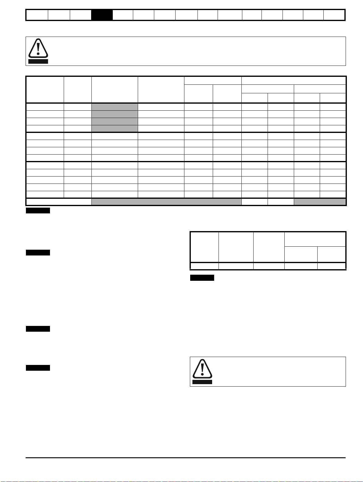
Safety
WARNING
NOTE
NOTE
NOTE
NOTE
NOTE
WARNING
Information
Product
information
Mechanical
installation
Electrical
installation
Getting
started
Basic
parameters
Running the
motor
Optimization
EtherCAT
interface
SMARTCARD
Operation
Onboard
PLC
Advanced
parameters
Technical
Data
Diagnostics
4.6 Ratings
Fuses
The AC supply to the drive must be installed with suitable protection against overload and short-circuits. The following section shows
recommended fuse ratings. Failure to observe this requirement will cause risk of fire.
Table 4-7 Fuse ratings and cable sizes
No of
Model
input
phases
DST1201 1
DST1202 1
DST1203 1
DST1204 1
Typical input
current
A
Maximum
continuous input
current
A
4.0 6 10 0.75 16 0.75 24
7.6 10 10 1 16 0.75 22
9.0 16 15 2.5 14 0.75 20
13.4 16 20 2.5 12 0.75 18
DST1201 3 3.1 3.5 6 10 0.75 16 0.75 24
DST1202 3 6.4 7.3 10 10 1 16 0.75 22
DST1203 3 8.6 9.4 16 15 2.5 14 0.75 20
DST1204 3 11.8 13.4 16 20 2.5 12 0.75 18
DST1401 3 2.6 2.8 4 10 0.75 16 0.75 24
DST1402 3 4.2 4.3 6 10 0.75 16 0.75 24
DST1403 3 5.9 6.0 8 10 0.75 16 0.75 22
DST1404 3 7.9 8.0 10 10 1 16 0.75 20
DST1405 3 9.9 9.9 12 15 1.5 14 0.75 18
Control cable
Fuse rating Cable size
IEC class
gG
Class CC
Input Output
2
mm
AWG
≥0.5 20
mm
2
UL listing
information
AWG
PVC insulated cable should be used.
Installation class (ref: IEC60364-5-52:2001)
B1 - Separate cables in conduit.
B2 - Multicore cable in conduit
C - Multicore cable in free air.
Cable sizes are from IEC60364-5-52:2001 table A.52.C with correction
factor for 40°C ambient of 0.87 (from table A52.14) for cable installation
method B2 (multicore cable in conduit).
Cable size may be reduced if a different installation method is used, or if
the ambient temperature is lower.
The recommended cable sizes above are only a guide. The mounting
and grouping of cables affects their current-carrying capacity, in some
cases smaller cables may be acceptable but in other cases a larger
cable is required to avoid excessive temperature or voltage drop. Refer
to local wiring regulations for the correct size of cables.
N
The recommended output cable sizes assume that the motor maximum
current matches that of the drive. Where a motor of reduced rating is
used the cable rating may be chosen to match that of the motor. To
ensure that the motor and cable are protected against overload, the
drive must be programmed with the correct motor rated current.
N
UL listing is dependent on the use of the correct type of UL-listed fuse,
and applies when symmetrical short-circuit current does not exceed
100kA. See Chapter 15 UL listing information on page 204 for sizing
information.
An MCB (miniature circuit breaker) may be used in place of fuses under
the following conditions:
• The fault-clearing capacity must be sufficient for the installation
• The I2T rating of the MCB must be less than or equal to that of the fuse
rating listed above.
A fuse or other protection must be included in all live connections to the
AC supply.
For a parallel DC bus system the maximum AC input fusing is shown in
Table 4-8 below.
Table 4-8 Maximum AC input fusing
Fuse rating
IEC class gG
Fuse rating
class CC
Input cable size
Model
AA
mm
2
AWG
All 20 20 4.0 12
Refer to the supplier of your drive for further information regarding DC
bus paralleling.
4.7 Output circuit and motor protection
The output circuit has fast-acting electronic short-circuit protection which
limits the fault current to typically no more than five times the rated
output current, and interrupts the current in approximately 20 µs. No
additional short-circuit protection devices are required.
The drive provides overload protection for the motor and its cable. For
this to be effective, Pr 0.46 Motor rated current must be set to suit the
motor.
Pr 0.46 Motor rated current must be set correctly to avoid a
risk of fire in the event of motor overload.
There is also provision for the use of a motor thermistor to prevent overheating of the motor, e.g. due to loss of cooling.
4.7.1 Motor cable size and maximum lengths
Since capacitance in the motor cable causes loading on the output of the
drive, ensure the cable length does not exceed the values given in Table
4-9.
Use 105 °C (221 °F) (UL 60/75 °C temp rise) PVC-insulated cable with
copper conductors having a suitable voltage rating, for the following
power connections:
Digitax ST User Guide 25
Issue: 5
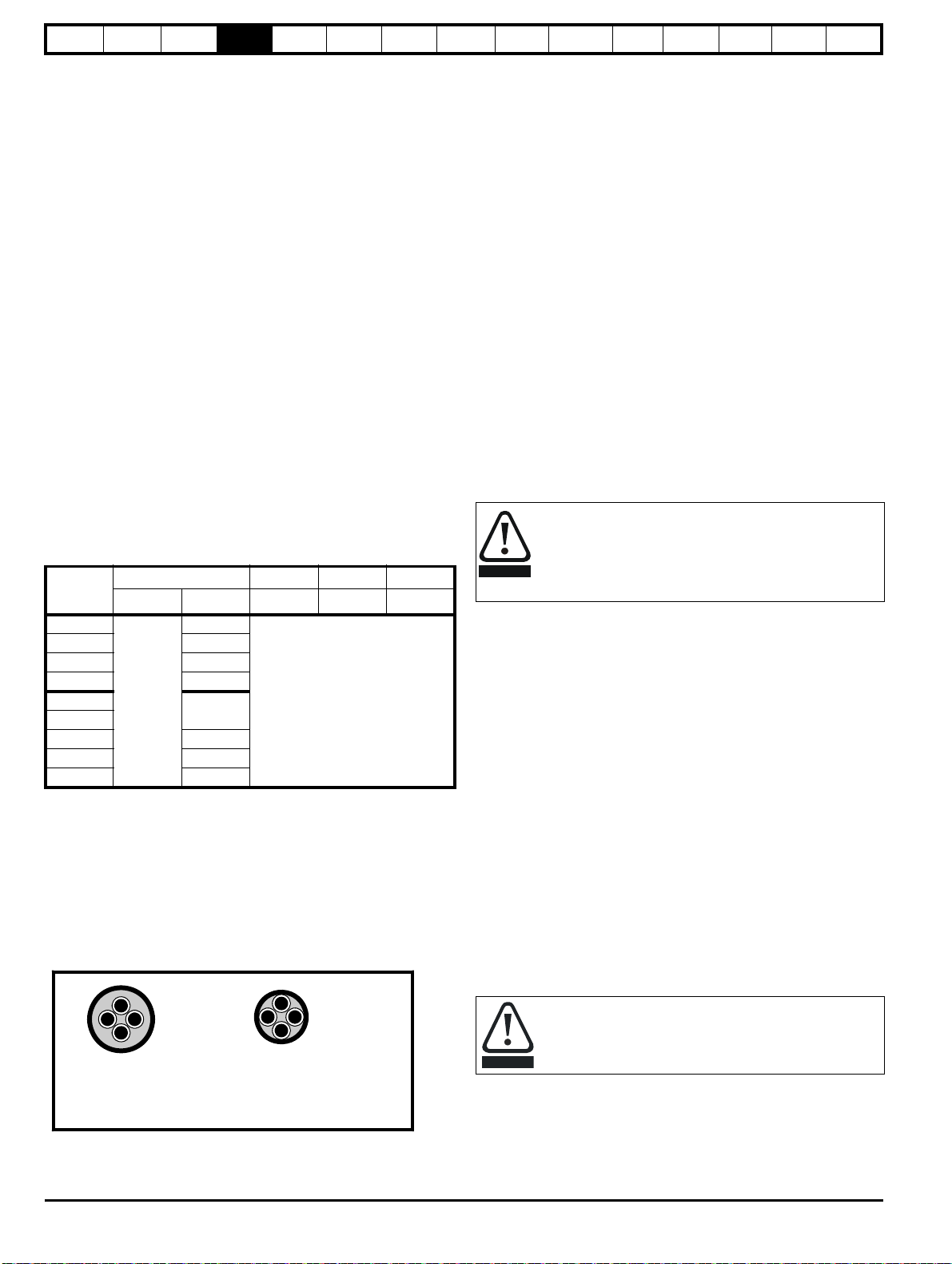
Safety
Normal capacitance
Shield or armour
separated from the cores
High capacitance
Shield or armour close
to the cores
WARNING
CAUTION
Information
Product
information
Mechanical
installation
Electrical
installation
Getting
started
Basic
parameters
Running the
motor
Optimization
EtherCAT
interface
SMARTCARD
Operation
Onboard
PLC
Advanced
parameters
Technical
Data
Diagnostics
UL listing
information
• AC supply to external EMC filter (when used)
• AC supply (or external EMC filter) to drive
• Drive to motor
• Drive to braking resistor
•
When operating in ambient >45 °C UL 75 °C cable should be used.
Cable sizes are given for guidance only and may be changed depending
on the application and the method of installation of the cables.
The mounting and grouping of cables affect their current capacity, in
some cases a larger cable is required to avoid excessive temperature or
voltage drop.
Input cable sizes should generally be regarded as a minimum, since
they have been selected for co-ordination with the recommended fuses.
Output cable sizes assume that the maximum motor current matches
that of the drive.
Where a motor of reduced rating is used the cable rating may be chosen
to match that of the motor.
To ensure that the motor and cable are protected against overload, the
drive must be programmed with the correct motor rated current.
• Cable lengths in excess of the specified values may be used only
when special techniques are adopted; refer to the supplier of the
drive.
• The default switching frequency is 6 kHz.
The drive power terminals are designed for a maximum cable size of 4.0
2
mm
(minimum 0.2 mm / 24 AWG).
Where more than one cable per terminal is used the combined
diameters should not exceed the maximum.
The terminals are suitable for both solid and stranded wires.
Table 4-9 Motor cable size and maximum lengths
Output cable 6kHz 8kHz 12kHz
Model
DST1201
mm
2
AWG m m m
24
DST1202 22
DST1203 20
DST1204 18
DST1401
DST1402
0.75
24
50
DST1403 22
DST1404 20
DST1405 18
High-capacitance cables
The maximum cable length is reduced from that shown in Table 4-9 if
high capacitance motor cables are used.
Most cables have an insulating jacket between the cores and the armor
or shield; these cables have a low capacitance and are recommended.
Cables that do not have an insulating jacket tend to have high
capacitance; if a cable of this type is used, the maximum cable length is
half that quoted in the tables. (Figure 4-3 shows how to identify the two
types).
Figure 4-3 Cable construction influencing the capacitance
4.7.2 Motor winding voltage
The PWM output voltage can adversely affect the inter-turn insulation in
the motor. This is because of the high rate of change of voltage, in
conjunction with the impedance of the motor cable and the distributed
nature of the motor winding.
For normal operation with AC supplies up to 500 Vac and a standard
motor with a good quality insulation system, there is no need for any
special precautions. In case of doubt the motor supplier should be
consulted.
Special precautions are recommended under the following conditions,
but only if the motor cable length exceeds 10 m:
• AC supply voltage exceeds 500 V
• DC supply voltage exceeds 670 V
• Operation of 400 V drive with continuous or very frequent sustained
braking
For the other cases listed, it is recommended that an inverter-rated
motor be used. This has a reinforced insulation system intended by the
manufacturer for repetitive fast-rising pulsed voltage operation.
If it is not practical to use an inverter-rated motor, an output choke
(inductor) should be used. The recommended type is a simple iron-cored
component with a reactance of about 2 %. The exact value is not critical.
This operates in conjunction with the capacitance of the motor cable to
increase the rise-time of the motor terminal voltage and prevent
excessive electrical stress.
4.7.3 Output contactor
If the cable between the drive and the motor is to be
interrupted by a contactor or circuit breaker, ensure that the
drive is disabled before the contactor or circuit breaker is
opened or closed. Severe arcing may occur if this circuit is
interrupted with the motor running at high current and low
speed.
A contactor is sometimes required to be installed between the drive and
motor for safety purposes.
The recommended motor contactor is the AC3 type.
Switching of an output contactor should only occur when the output of
the drive is disabled.
Opening or closing of the contactor with the drive enabled will lead to:
1. OI.AC trips (which cannot be reset for 10 seconds)
2. High levels of radio frequency noise emission
3. Increased contactor wear and tear
The Drive Enable terminal (T31) when opened provides a Safe Torque
Off function. This can in many cases replace output contactors.
For further information see section 4.17 Safe Torque Off on page 42.
4.8 Braking
The internal braking resistor can be used with the drive even though its
resistance is lower than the minimum resistance values given in
Table 4-11, because of the following reasons.
• The braking resistor overload protection function in the drive is set
up to limit the power dissipated in the resistor.
• The braking resistor is installed with a thermistor which will trip the
drive if the resistor is too hot.
• The power rating of the resistor is only 50 W
The internal braking resistor for Digitax ST is installed with a
thermistor which must be connected to the drive whenever
the internal braking resistor in installed.
If an external resistor is used with the drive, its resistance must be equal
to or greater than the value given in Table 4-11.
The cable used for Table 4-9 is shielded and contains four cores. Typical
capacitance for this type of cable is 130 pF/m (i.e. from one core to all
others and the shield connected together).
26 Digitax ST User Guide
Issue: 5
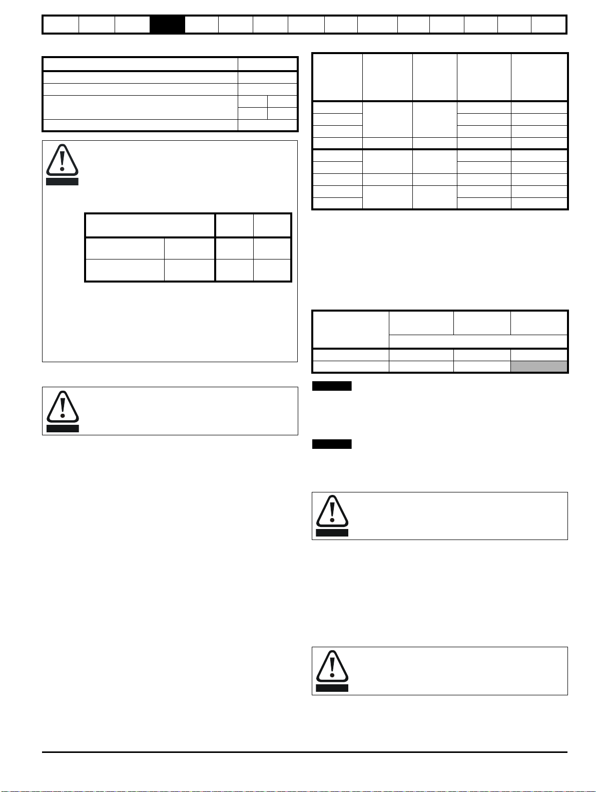
Safety
CAUTION
Parameter
200 V
drive
400 V
drive
Full power braking
time
Pr 10.30 0.06 0.01
Full power braking
period
Pr 10.31 2.6 1.7
WARNING
NOTE
NOTE
WARNING
WARNING
Information
Product
information
Mechanical
installation
Electrical
installation
Getting
started
Basic
parameters
Running the
motor
Optimization
EtherCAT
interface
SMARTCARD
Operation
Onboard
PLC
Advanced
parameters
Technical
Data
Diagnostics
UL listing
information
Table 4-10 Internal braking resistor data
Parameter
Part number 1299-0001
DC resistance at 25 °C 70 Ω
Peak instantaneous power over 1ms at nominal
resistance
200 V 400 V
2.2 kW 8.7 kW
Average power over 60 s 50 W
Braking resistor overload protection parameter settings
Failure to observe the following information may
damage the resistor.
The drive’s software contains an overload protection
function for a braking resistor. On Digitax ST this function is
enabled at default to protect the internally mounted resistor.
Below are the parameter settings.
For more information on the braking resistor software
overload protection, see Pr 10.30 and Pr 10.31 full
descriptions in the Advanced User Guide.
If the internally mounted braking resistor is to be used at
more than half of its average power rating then the drive's
cooling fan must be at full speed, controlled by setting
Pr 6.45 to On (1).
4.8.1 External braking resistor
Overload protection
When an external braking resistor is used, it is essential that
an overload protection device is incorporated in the braking
resistor circuit.
When a braking resistor is to be mounted outside the enclosure, ensure
that it is mounted in a ventilated metal housing that will perform the
following functions:
• Prevent inadvertent contact with the resistor
• Allow adequate ventilation for the resistor
When compliance with EMC emission standards is required, external
connection requires the cable to be armored or shielded, since it is not
fully contained in a metal enclosure. See section 4.10 EMC
(Electromagnetic compatibility) on page 28 for further details.
Internal connection does not require the cable to be armored or
shielded.
Table 4-11 Minimum resistance and power ratings
Average
power for
0.25s
Model
Minimum
resistance*
Peak
power
rating
Continuous
power rating
Ω kW kW kW
DST1201
DST1202 1.2 3.5
23 6.6
0.5 1.6
DST1203 1.6 4.9
DST1204 16 9.3 2.3 7.0
DST1401
DST1402 1.4 4.1
111 5.5
0.8 2.3
DST1403 75 8.1 2.0 6.1
DST1404
DST1405 4.1 12.2
28 21.7
3.0 9.0
* Resistor tolerance: ±10 %
4.9 Ground leakage
The ground leakage current depends upon whether the internal EMC
filter is installed. The drive is supplied with the filter installed. Instructions
for removing the internal filter are given in Figure 4-4.
With the internal EMC filter installed the ground leakage current is as
follows:
Table 4-12 Ground leakage current with internal EMC filter installed
3 phase Star
Model
ground
DST120X at 220 V 4 10 3
DST140X at 400 V 12 40
The above leakage current is just the leakage current of the drive with the
internal EMC filter connected and does not take into account any leakage
currents of the motor or motor cable.
With internal EMC filter removed the ground leakage current = <1 mA.
In both cases, there is an internal voltage surge suppression device
connected to ground. Under normal circumstances, this carries
negligible current.
When the internal EMC filter is installed, the leakage current
is high. In this case, a permanent fixed ground connection
must be provided with a cross sectional area equal to 10mm
4.9.1 Use of residual current device (RCD)
There are three common types of ELCB / RCD:
1. AC - detects AC fault currents
2. A - detects AC and pulsating DC fault currents (provided the DC
current reaches zero at least once every half cycle)
3. B - detects AC, pulsating DC and smooth DC fault currents
• Type AC should never be used with drives
• Type A can only be used with single phase drives
• Type B must be used with three phase drives
3 phase Delta
ground
mA
1 phase
2
.
Digitax ST User Guide 27
Issue: 5
Only type B ELCB / RCD are suitable for use with 3 phase
inverter drives.
If an external EMC filter is used, a delay of at least 50ms should be
incorporated to ensure spurious trips are not seen. The leakage current
is likely to exceed the trip level if all of the phases are not energized
simultaneously.
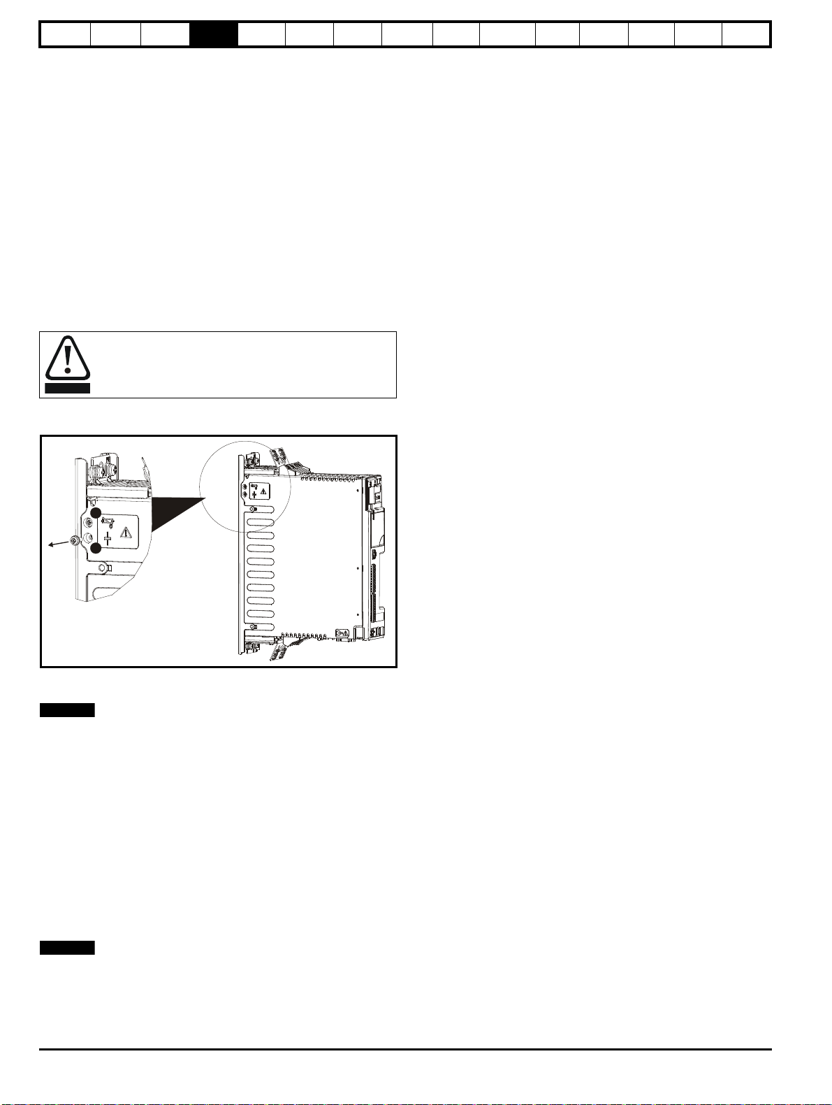
Safety
WARNING
1
2
NOTE
NOTE
Information
Product
information
Mechanical
installation
Electrical
installation
Getting
started
Basic
parameters
Running the
motor
Optimization
4.10 EMC (Electromagnetic compatibility)
4.10.1 Internal EMC filter
It is recommended that the internal EMC filter is kept in place unless
there is a specific reason for removing it.
Special attention is required when using a DST120X model on an
ungrounded supply (IT supply). In the event of a ground fault in the
motor circuit the drive may not trip and the filter could be overstressed.
In this case, either the filter must be removed or additional independent
motor ground fault protection must be provided.
The internal EMC filter reduces radio-frequency emissions into the line
power supply. Where the motor cable is short, it permits the
requirements of EN 61800-3:2004 to be met for the second environment.
For longer motor cables, the filter continues to provide a useful reduction
in emission level, and when used with any length of shielded cable up to
the limit for the drive, it is unlikely that nearby industrial equipment will be
disturbed. It is recommended that the filter be used in all applications
unless the ground leakage current is unacceptable or the above
conditions are true.
The supply must be disconnected before removing the
internal EMC filter or line to ground varistor screws.
EtherCAT
interface
SMARTCARD
Operation
Onboard
PLC
Advanced
parameters
Technical
Data
Diagnostics
UL listing
information
Figure 4-4 Removing the internal EMC filter and line to ground
varistors
1. Internal EMC filter. Remove the bottom screw as shown.
2. Line to ground varistors. Remove the top screw as shown.
The line to ground varistors should only be removed in special
circumstances.
4.10.2 Further EMC precautions
Further EMC precautions are required if more stringent EMC emission
requirements apply:
• Operation in the first environment of EN 61800-3:2004
• Conformity to the generic emission standards
• Equipment which is sensitive to electrical interference operating
nearby
In this case it is necessary to use:
• The optional external EMC filter
• A shielded motor cable, with shield clamped to the grounded metal
panel
• A shielded control cable, with shield clamped to the grounded metal
panel via the grounding bracket.
It is not necessary to remove the external EMC filter when using an IT
supply.
28 Digitax ST User Guide
Issue: 5

Safety
Metal back
plate
External
controller
Signal cables
Plan for all signal cables
to be routed at least
300mm (12in) from the
drive and any power cable
Optional
braking resistor
Locate optional braking
resistor and overload
external to cubicle
(preferably near to or
on top of the cubicle).
Note
For EMC compliance:
1) When using an external EMC
filter, one filter is required for
each drive
2) Ensure direct metal contact
at drive and filter mounting
points (any paint must be
removed)
The external EMC filter can be
bookcase mounted (next to the
drive) or footprint mounted (with
the drive mounted onto the filter).
Thermal
overload
protection
device
AC supply
contactor and
fuses or MCB
Information
Product
information
Mechanical
installation
Electrical
installation
Getting
started
Basic
parameters
4.10.3 Recommended cable management
Figure 4-5 Drive cable clearances
Running the
motor
Optimization
EtherCAT
interface
SMARTCARD
Operation
Onboard
PLC
Advanced
parameters
Technical
Data
Diagnostics
UL listing
information
Digitax ST User Guide 29
Issue: 5
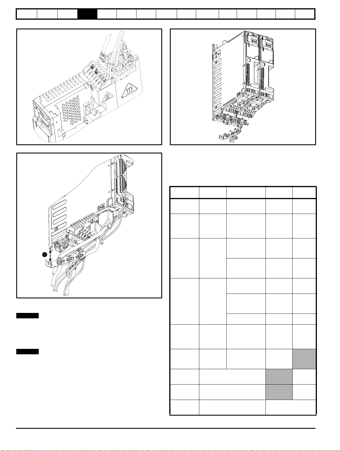
Safety
1
NOTE
NOTE
Information
Product
information
Mechanical
installation
Electrical
installation
Getting
started
Basic
parameters
Running the
motor
Optimization
EtherCAT
interface
SMARTCARD
Operation
Onboard
PLC
Advanced
parameters
Technical
Data
Diagnostics
UL listing
information
Figure 4-6 Grounding bracket at the top of the drive
Figure 4-7 Grounding bracket at the bottom of the drive
Grounding bracket and drive to be directly connected to a grounded
backplate.
1. The distance for EMC (shown in Figure 4-7 above) from the drive is as
follows:
200 V drive - Allowance up to 65 mm (2.56 in)
400 V drive - Allowance up to 100 mm (3.94 in)
The grounding bracket can remain mounted when the drive is removed.
as follows.
Figure 4-8 Multiple drives with single grounding bracket
If installing multiple drives, one grounding bracket can be used for two
drives.
4.11 Internal and external conducted emissions conformity
Table 4-13 Immunity compliance
Standard
IEC61000-4-2
EN61000-4-2
IEC61000-4-3
EN61000-4-3
IEC61000-4-4
EN61000-4-4
IEC61000-4-5
EN61000-4-5
IEC61000-4-6
EN61000-4-6
IEC61000-4-11
EN61000-4-11
IEC61000-6-1
EN61000-61:2007
IEC61000-6-2
EN61000-62:2005
EN 618003:2004
IEC61800-3
Type of
immunity
Electrostatic
discharge
Radio
frequency
radiated field
Test specification Application Level
6 kV contact
discharge
8 kV air discharge
10V/m prior to
modulation
80 - 1000 MHz
80 % AM (1 kHz)
modulation
5/50 ns 2 kV
transient at 5 kHz
repetition frequency
Fast transient
burst
via coupling clamp
5/50 ns 2 kV
transient at 5 kHz
repetition frequency
by direct injection
Common mode 4 kV
1.2/50 μs
waveshape
Surges
Differential mode 2
kV
1.2/50 μs
waveshape
Lines to ground
Conducted
radio
frequency
Voltage dips
and
interruptions
10V prior to
modulation
0.15 - 80 MHz
80 % AM (1 kHz)
modulation
-30 % 10 ms
+60 % 100 ms
-60 % 1 s
<-95 % 5 s
Generic immunity standard for the
residential, commercial and light industrial environment
Generic immunity standard for the
industrial environment
Product standard for adjustable
speed power drive systems
(immunity requirements)
Module
enclosure
Module
enclosure
Control lines
Level 3
(industrial)
Level 3
(industrial)
Level 4
(industrial
harsh)
Power lines
AC supply
lines:
Level 3
(industrial)
Level 4
line to ground
AC supply
lines:
line to line
Signal ports
to ground
Control and
power lines
AC power
ports
Level 3
Level 2
Level 3
(industrial)
Complies
Complies
Meets immunity
requirements for first and
second environments
30 Digitax ST User Guide
Issue: 5
 Loading...