

Page 1
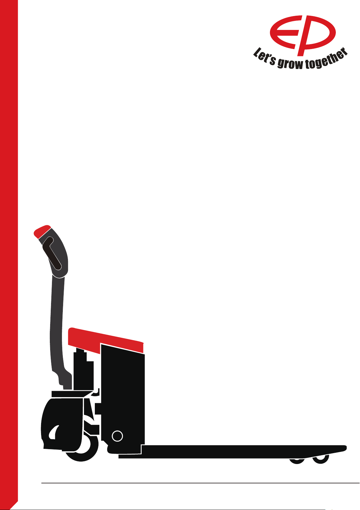
Operation Manual
EPL151
HPL152
WPL201
RPL201/RPL201H
Original Instruction Part No.508000003010
V2 12/2019
Page 2

EP EQUIPMENT CO.,LTD. is one of the world’s
leading companies manufacture, design
material handling equipment and provide related
service. With over 100,000 square metres plant
it produces over 100,000 trucks per year, and
provides professional, eective and optimized
material handling solutions worldwide, until now
it has developed three major kinds of business:
Material handling equipment: Focus
•
on electric forklift and warehouse
equipment
OEM parts: Global parts supply
•
Imow industry,online: One-stop
•
industrial products supply
Guided by our customer-oriented concept, EP
has developed service centers in more than
30 countries around the world, from which
customers are able to receive timely local
service. Moreover, 95% of warranty parts can be
shipped out within 24 hours after been ordered.
Through our online after-sales service system,
customers can process their warranty claims,
order spare parts and consult the operation
manuals, maintenance materials and spare
parts catalogs.
With business all over the world, EP has
thousands of employees and hundreds
of agents worldwide to provide our global
customers with prompt local service.
Based on the concept of sharing economy ,
EP also oer rental service for various logistics
equipment. Adhering to the idea “Making the
leasing of logistic equipment more simple”,
EP is devoted to providing customized one-
stop leasing solutions for our customers with
our high quality, reasonable price and prompt
rental service.
EP’s mission&vision is “ Let more people apply
the electrical material handling equipment to
relieve the intensity of labour” and “Let’s grow
together”.
EP EQUIPMENT CO., LTD
Address: XIAQUAN, DIPU, ANJI,
ZHEJIANG, CHINA
Tel: + 86-0571-28023920
Website: www.ep-ep.com
Email: [email protected]
Page 3
Preface
i
Thank you for buying our products.
The manual will show you the way of correctly using the truck as well as relevant preventive
maintenance and safety operation. The truck should be operated only by well-trained professionals
and by no means by non-working personnel. Operators are supposed to read through the manual
before actually operating the truck.
Explanations on the manual
With the continuous upgradation and improvement of our company’s products, you may find a
slight dierence existing between your carrier and some introductions in the manual.
All the information, specications and illustrations in the manual are eective in times of printing
and our company maintains the right to modify the specication (s) or design (s) of our products at
any time without any beforehand notication.
Safety signs and corresponding esplations
DANGER
Means that failure to comply can cause risk to life and/or major damage to property.
WARNING
Please strictly adhere to these safety instructions to avoid personal injury or major damage to
equipment.
CAUTION
Please pay attention to the important safety instructions.
NOTE
Pay attention to Instruction.
Internet address and QR code of
Parts manual
By entering the address http://www.epcare.com in a web browser or by
scanning the QR code, Login after
registration, Select “Parts purchase"
function and input part number or model
name to nd the truck.
Note:
After registration, please send email
to info@ ep-care.com to activate your
account
Page 4

Use provisions
The kind of carrier introduced in the manual belongs to ground delivery equipment applicable to
goods uplifting and delivery, and it must be used, operated and maintained in strict accordance with
the provisions in the operation instruction. All the other uses of the equipment beyond the operation
instruction shall be regarded as operation behaviors violating the provisions of the operation
instruction that may result in personnel injury or losses on the carrier or other properties. The most
important thing (for operators) is to keep the carrier away from excessive or unbalanced loading
while strictly abiding by the maximum loading capacity specied in corresponding nameplate or
loading diagram. The carrier should not be used in the areas with such dangers as re disaster and
explosion or likely to result in corrosion, rusting or large dusts.
Obligations and responsibilities of equipment user
In the manual, “equipment user” refers to any natural person or legal person directly using or
appointing or authorizing others to use the carrier. In such special situations as renting or sales,
the “equipment user” represents the interested parties supposed to bear operation obligations
as specied by the contractual terms concluded between equipment owner and corresponding
users. Equipment users must ensure the use of the carrier only for purposes specied and timely
eliminate all the dangers that may threaten the life and health of the users themselves or any other
third party, in addition to which they must also strictly abide by accident prevention provisions,
other safety technology provisions and equipment operation, maintenance and repair guidelines,
and ensure that all the operators seriously read and completely understand the contents of the
operation instruction.
Should any violation of the operation instruction occur, the quality guarantee of our company will be
invalid automatically, and our company will assume none of the responsibilities for losses resulting
from any nonstandard operation of the equipment implemented by any client, equipment user or
any third party without the authorization of the client service department of our company.
Equipment ret
Any installation or retrotting of any additional device that may inuence or enhance the functions
of the carrier must be approved by our company in writing beforehand.
Company name: Zhejiang EP Equipment Co., Ltd
Address: Zhongli Industrial Park, Xiquan Village, Dipu Town,
Anjij County, Huzhou City, Zhejiang Province
Website: www.ep-ep.com
Telephone: 86-571-28035656/28878695
E-mail:[email protected]
Page 5

Legal requirements for marketing
Declaration
EP EQUIPMENT CO., LTD.
Address: XIAQUAN, DIPU, ANJI, ZHEJIANG, CHINA
We declare that the machine
Industrial truck: according to this operation manual
Type: according to this operation manual
complies with the most recent version of Machinery Directive 2006/42/EC.
Personnel authorised to compile the technical documents:
See EC/EU Declaration of Conformity
EP EQUIPMENT CO., LTD.
EC/EU Declaration of Conformity
The manufacturer declares that this industrial truck complies with the EC Machinery Directive
and the provisions of other applicable EC/EU directives eective at the time of sale. This can be
veried by means of the EC/EU Declaration of Conformity and the relevant certication label on the
nameplate.
The industrial truck is supplied with the EC/EU Declaration of Conformity document. This
declaration proves that this truck complies with the requirements of the EC Machinery Directive.
Unauthorised modication or additional installation of equipment to the structure of the industrial
truck may aect its safety, and will therefore invalidate the EC/EU Declaration of Conformity.
The EC/EU Declaration of Conformity must be carefully stored and made available to be presented
to the relevant authorities when necessary. If this industrial truck is sold, this declaration document
must be handed over to the new owner.
Page 6

Table of contents
A Nameplates and alarming labels ..........................................................................................A1
B Operation .............................................................................................................................B1
2.1Utilization safety specication..............................................................................................B1
2.1.1 EN standards ...................................................................................................................B2
2.1.2 Conditions for application ...............................................................................................B2
2.1.3 Stability ...........................................................................................................................B2
2.2 Display and manipulation ...................................................................................................B3
2.2.1 Control handle .................................................................................................................B3
2.2.2 Key switch ......................................................................................................................B4
2.2.3 Display instrument ...........................................................................................................B5
2.3 Truck use and operation .....................................................................................................B8
2.3.1 Preparation for use ..........................................................................................................B8
2.3.2 Truck starting .................................................................................................................B10
2.3.3 Running, swerving and braking .....................................................................................B11
2.3.4 Goods picking ................................................................................................................B14
2.3.5 Parking the truck securely .............................................................................................B15
2.3.6 Drive directions ..............................................................................................................B16
2.3.7 Loading ..........................................................................................................................B17
2.3.8 Using the truck on a slope .............................................................................................B18
2.3.9 Truck transport...............................................................................................................B19
2.3.10 Operating the truck without its own drive system ........................................................B20
C Storage battery use and maintenance .................................................................................C1
3.1 Safety and warning .............................................................................................................C1
3.2 Storage battery charging ....................................................................................................C2
3.2.1 Precautions......................................................................................................................C2
3.2.2 Charging the battery with internal charger.......................................................................C2
3.2.3 Charging the battery with external charger......................................................................C3
3.2.4 Battery type & dimensions&Charging time ......................................................................C4
3.3 Handling of the lithium-ion battery .....................................................................................C5
3.3.1 Information on the conformity of lithium-ion batteries .....................................................C5
3.3.2 Special lithium-ion safety rules .......................................................................................C5
3.3.3 Transportation .................................................................................................................C6
3.3.4 Scrapping lithium-ion batteries .......................................................................................C6
3.3.5 Storage ...........................................................................................................................C7
3.3.6 Scrapping lithium-ion batteries .......................................................................................C7
3.3.7 Disposal of Used Battery Packs .....................................................................................C7
3.4 Battery removal and installation .........................................................................................C6
D Maintenance ........................................................................................................................D1
4.1 Truck maintenance .............................................................................................................D1
4.2 Maintenance table ..............................................................................................................D2
E Technical data .......................................................................................................................E1
Pg.
Page 7
Nameplates and alarming labels
A
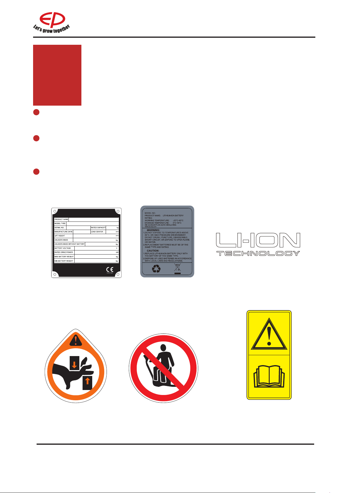
Have the nameplates of a truck xed its main body and alarming labels pasted on its
outer cover.
Should any nameplate or alarming label lose or be damaged, please conduct
replacement immediately or contact with the sales department or corresponding agent
of our company when necessary.
Such truck-related information as product model, serial number, manufacturing date,
rated load lifting capacity, lifting height, load centre distance and dead weight are all
shown in the nameplates.
Nameplate
Anti-pinch label
Battery nameplate
Do not rest on the pallet label
Lithium label
Instructions label
1A
REV. 12/2019
Page 8
Hoisting
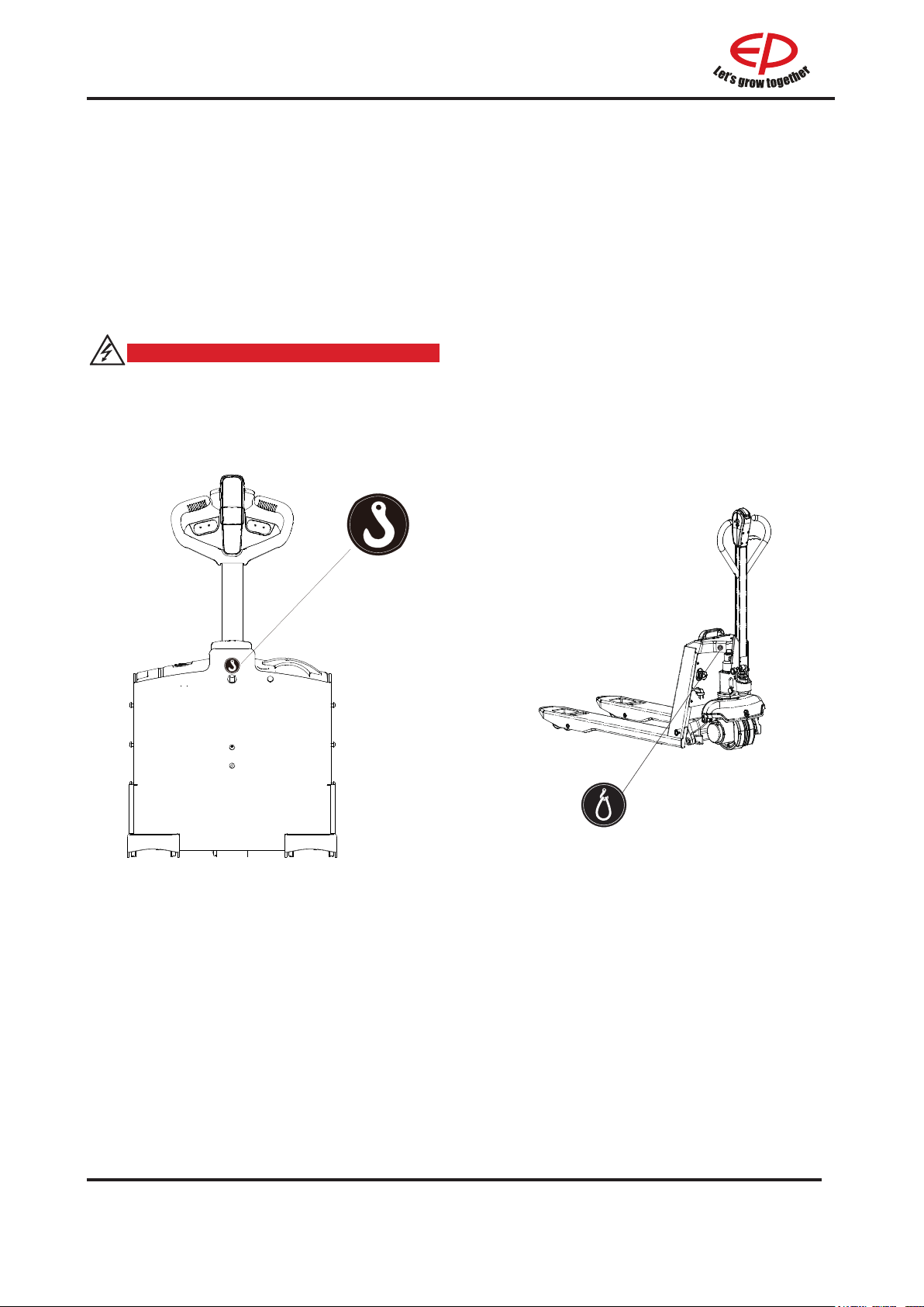
Remove the load before hoisting the pallet
truck.
Disconnect the power supply.
Attach slings in the positions identied by
the hook symbol.
DANGER
Personnel must not stand below or near
the truck when the pallet truck is being
lifted.
WPL201
REV. 12/2019
HPL152
2A
Page 9
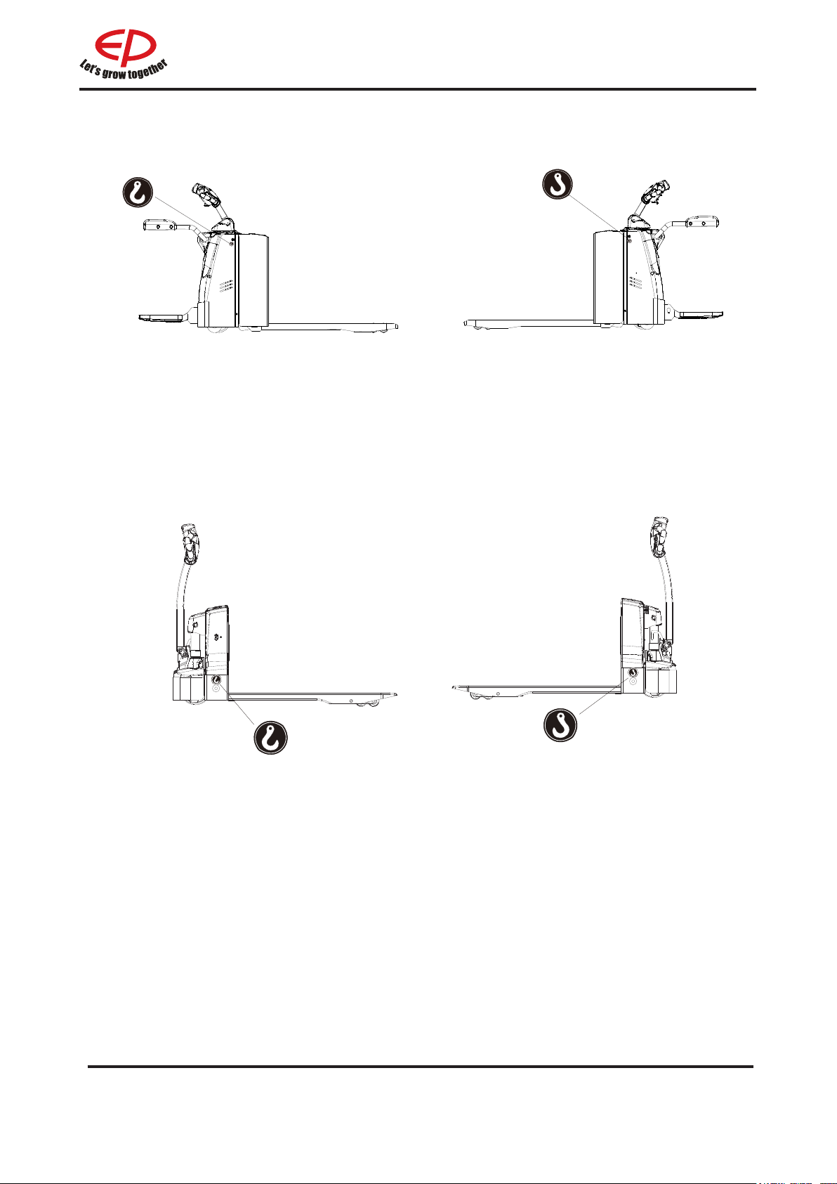
RPL201/ RPL201H
EPL151
3A
REV. 12/2019
Page 10

Operation
i
i
B
Applicable environment
temperature: -10 °C - 40 °C
NOTE
The carrier can by no means be used under the temperature lower than 5 °C for a long time,
or in refrigeratory or under the condition that such environmental factor as temperature or
humidity changes extremely before special equipment is additionally installed and the permit
of the manufacturer is acquired.
2.1Utilization safety specication
Don’t use the truck in
rainwater.
Don’t use the truck in nonposition.
Avoid the use of the truck by
non-working personnel.
Don’t ride on the truck.
Don’t carry or lift people by the
truck.
NOTE
Conditions of operation road surface: the truck should run on solid, at, level and paved road
surfaces (including both running and lifting)
Don’t use the truck on
slippery road surfaces.
(such as road surfaces with
oil stain or residual snow or
those frozen ones )
1
B
Don’t carry goods on
steep slope to prevent
goods from sliding o.
REV. 12/2019
Page 11

Don’t leave the truck before
it is parked as regulated.
2.1.1 EN standards
Don’t use the truck when any
non-working personnel is in the
dangerous area.
Don’t be distracted when using
the truck.
Don’t be distracted when using
the truck.
Don’t place any part
of your body in any
moving part of the truck
to avoid being clamped.
Continuous sound level:
<
74 dB(A)
according to EN 12053 as stipulated in ISO 4871
The continuous sound level is a value averaged according to standard regulations, taking
the sound pressure level into account when driving, lifting and idling. The sound pressure
level is measured at the ear.
Electromagnetic compatibility (EMC)
The manufacturer conrms compliance with the limit values for electromagnetic emission
and interference immunity as well as testing of static electricity discharge according to EN
12895 and the references to other standards contained therein.
Electrical or electronic components and their arrangement may only be modied after
written approval by the manufacturer has been obtained.
REV. 12/2019
2B
Page 12

2.1.2 Conditions for application
Working condition requirements:
- Indoor use and outdoor use.
- The walking, lifting and lowering devices, harness and components are IP55 dust and waterresistant
- The truck's maximum operation altitude is up to 2000m.
- Trucks can only be operated in adequately illuminated working areas to avoid injuries. In case
of insucient light, an additional lighting equipment is needed to ensure that the driver can see
properly.
If you must travel on an incline, the gradients should be below A% at full load, or below B%
without a load.(For the value of A and B, refer to the Gradability in technical data)
2.1.3 Stability
Stability is guaranteed if your truck is used properly in accordance with its intended
purpose. Common reasons for a loss of truck stability include:
• Emergency stops or sharp turns
• Driving with a raised load or a load handling device
• Turning the vehicle around on or driving across a slope
• Driving up or down a slope with the load pointing downhill
• Driving with a wide load
• Carrying a swinging load
• Driving near the edge of a ramp or up steps
• Tilting the mast forward while carrying a
raised load
• Driving on uneven surfaces
• Overloading the truck
• Carrying bulky loads in strong winds
• When carrying liquid, its centre of mass inside the container may shift due to
inertial force (such as when pulling away, braking or turning)
3
B
REV. 12/2019
Page 13
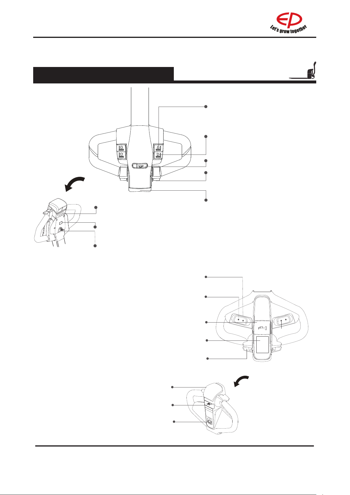
2.2.1 Control handle
1.Control handle A
EPL151/RPL201/
RPL201H
2.2Display and manipulation
Lowering button
Lower loading parts
Lifting button
Lift loading parts
Horn button
Send out sound warning signals
Driving switch
Controls travel direction and speed
Tortoise speed button
(Not for RPL201/RPL201H)
Display instrument
Display the electric quantity of the truck
(Not for
RPL201/RPL201H
Key switch
Connect and interrupt control current
Lowering button
Lower loading parts
Lifting button
Lift loading parts
Horn button
Send out sound warning signals
Display instrument
Display the electric quantity of the truck
Driving switch
Controls travel direction and speed
Emergency reverse button
Through touching the button, truck
drives away from operator.
)
WPL201
Emergency reverse button
Through touching the button, truck drives
away from operator.
REV. 12/2019
Tortoise speed button
Key switch
Connect and interrupt control current
4B
Page 14
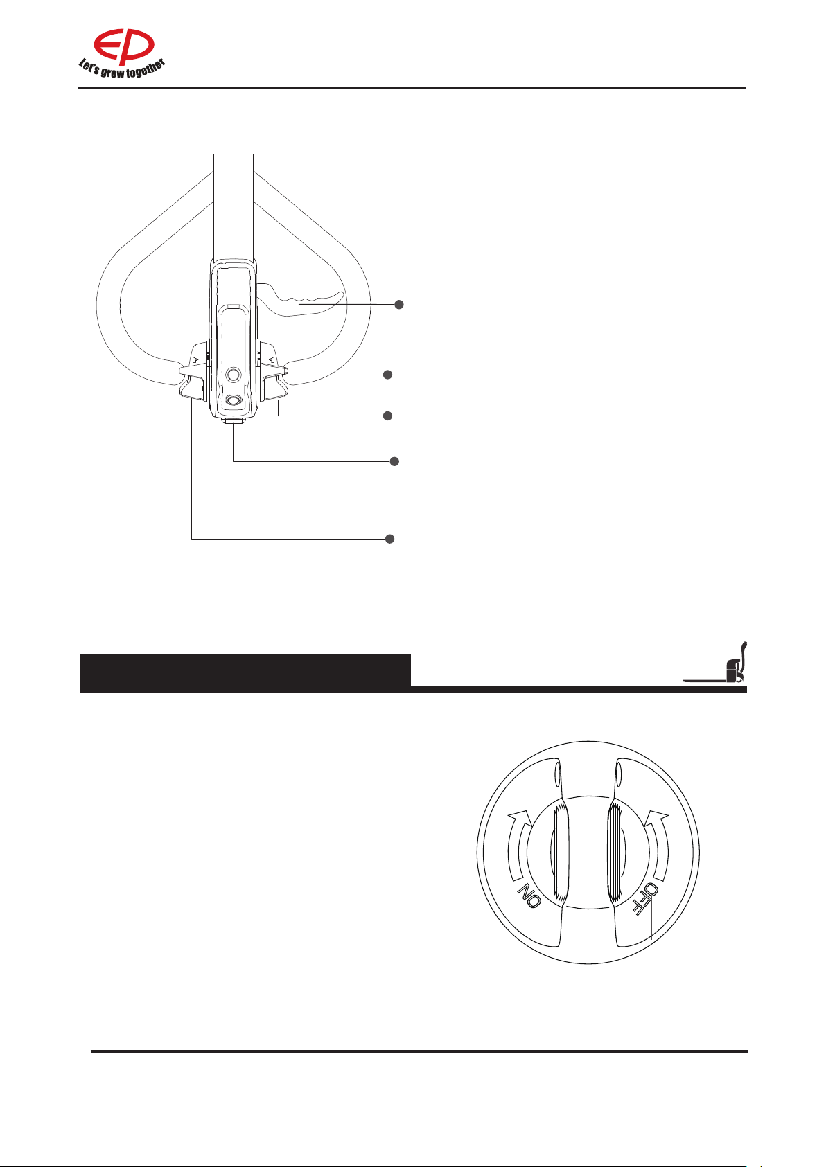
HPL152
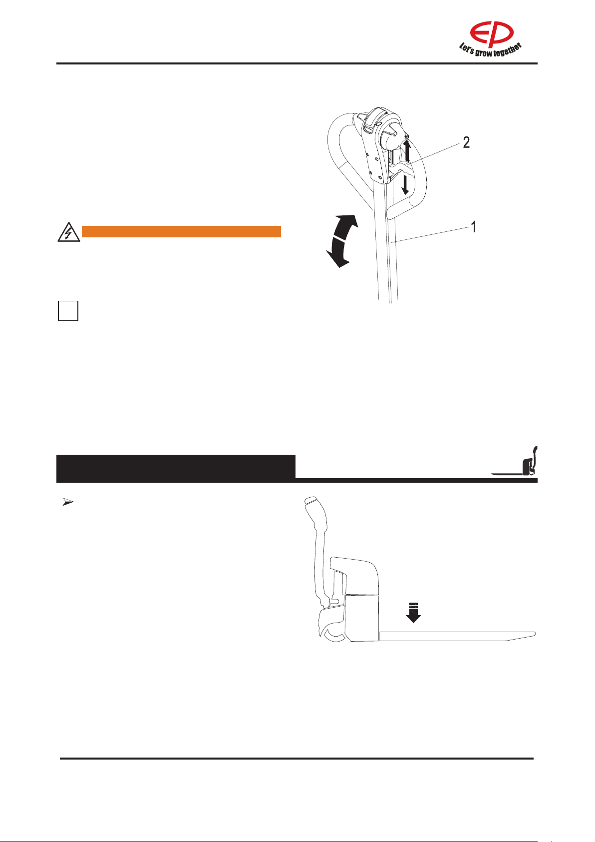
Lowering lever
Pull and hold the manual lower switch (2).The
forks will lower to the minimum height until they
stop by themselves.
Power switch button
Start the truck
"Horn" button
Activates the horn.
Emergency reverse switch
Press the emergency reverse switch. The
vehicle will begin to travel in the opposite
direction.
Drive switch
Select the required driving direction and speed.
2.2.2 Key switch
1.Key switch A
Connect and interrupt control current.
• When the key rotates to gear “OFF”, the
control current of the truck will be interrupted;
• When the key rotates to gear “ON”, the
control current of the truck will be connected.
RPL201/RPL201H/EPL151
5
B
REV. 12/2019
Page 15
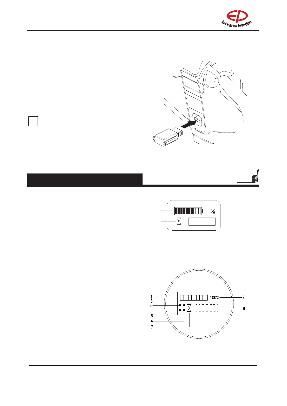
2.Key switch B
1
2
3
4
70%
i
Connect and interrupt the control
current.
When pulling out the induction key, the
•
control current of the truck will be interrupted;
• When inserting the induction key, the control
current of the truck will be connected.
NOTE
Pulling out the key switch of a forklift
before leaving can prevent the forklift
from starting accidentally.
2.2.3 Display instrument
WPL201
• LED (1) displays the remaining charge;
• LED (2) displays remaining charge
percentage;
• LED (3) displays Interlock switch status
indication;
• LED (4) displays the total running time
normally. If fault, display the fault code.
• LED (1) displays the remaining charge.when
1st block and 2nd block blinks alternatively,
it indicates low power needs to be charged
• LED (2) displays remaining charge
percentage;
• LED (3) ashing, it indicates travel forward
properly;
• LED (4) ashing, it indicates travel backward
properly;
• LED (5) ashing, it indicates lifting properly;
• LED (6) ashing, it indicates lowering
properly;
• LED (7) always on, it indicates interlock
switch opened, LED(7) ashing, it indicates
interlock switch closed, the display start
timing.
• LED (8) displays the total running time
normally. If fault, display the fault code.
EPL151
RPL201/RPL201H
REV. 12/2019
6B
Page 16
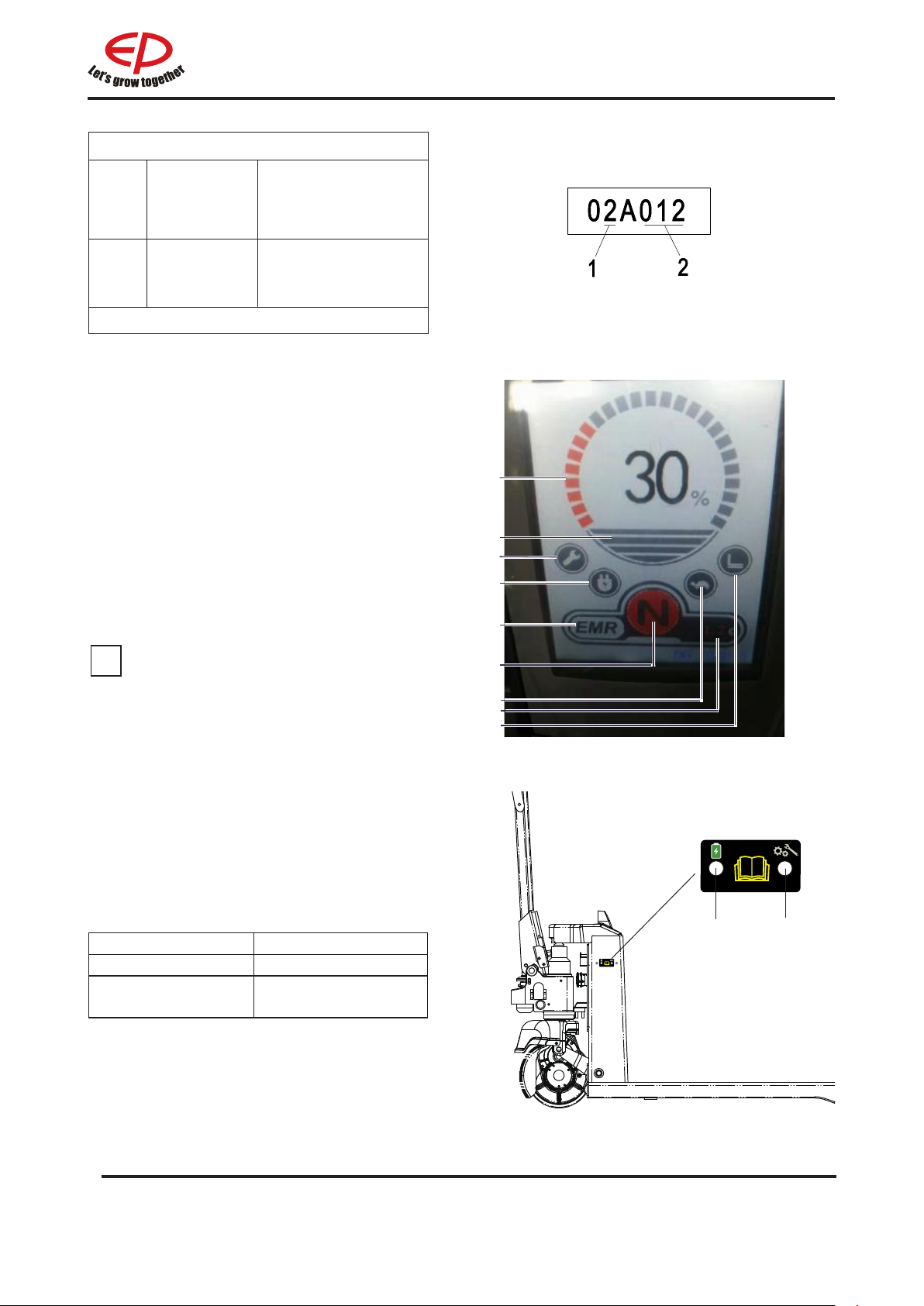
Error Code
i
2 = Traction
1
Controller
number
controller
6 = Steering
controller
2
• LED (1) displays the remaining charge;
• LED (2) indicate the speed of truck.
• LED (3) indicate fault warning;
• LED (4) indicate charging status,when
charging, it turns into a battery;
• LED (5) indicate emergency reverse switch
status;
• LED (6) indicate truck stop or walk, if the
truck stop display"P", if the truck travel
display"N";
• LED (7) indicate turtle speed status;
• LED (8) indicate rise and fall indication.
• LED (9) indicate the operating hours.
Error code note
Note: Consult the service manual
NOTE
Low Voltage Protection
The car has low voltage protection
function.
When the battery power of forklift truck is
7%-15%, the display screen shows L1.
At this time, the forklift truck can not lift
goods, but it can run normally. When the
battery power is less than 7%, the display
screen shows L2. At this time, the forklift
can not be lifted and the driving speed
becomes slower.
1
9
2
3
4
5
6
8
7
WPL201
LCD (1) displays the state of charge;
DISPLAY DESCRIPTION
Continuous red Charge is charging
Continuous green Battery charging is
complete
The LCD (2) remain green light lit under
normal, ashing show the failure state of
truck.
1
7
B
2
REV. 12/2019
Page 17
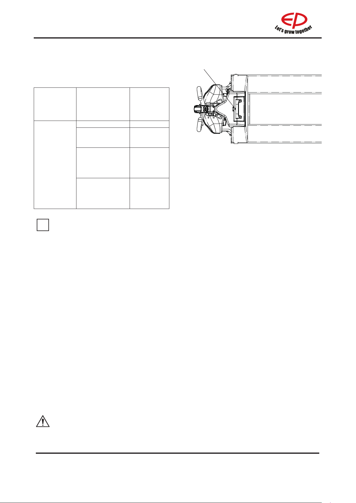
The LCD display (3) show battery residual
i
capacity.
The color of the LCD (3) represent the
following conditions:
Residual
Component LCD color
Green 30-100%
Continuous
Yellow
Standard
battery
residual
capacity
After the red light starts flashing, the battery will enter the low-voltage protection state.
According to the battery state, The truck will appear accidental power-o protection. Please
charge the battery after restarting to avoid damage to the battery.
Slow
ashing red
light(Flashing
period 2s)
Quick ashing
red light
(Flashing period
1s)
capacity
15-30%
7-15%
0-7%
3
HPL152
If the controller detects a battery failure, ashes of LCD(3) represent battery failure information
until the failure is remedied. Details of failure information are shown as below:
Under-voltage of single cell battery: The green light repeats in a cycle of flashing once in 1
•
second, pausing for 2 seconds and then ashing twice, pausing for 3 seconds.
Over-voltage of single cell battery: The green light repeats in a cycle of flashing once in 1
•
second, pausing for 2 seconds and then ashing three times, pausing for 3 seconds.
Short circuit protection: The green light repeats in a cycle of ashing once in 1 second, pausing
•
for 2 seconds and then ashing four times, pausing for 3 seconds.
Over-current protection: The green light repeats in a cycle of ashing once in 1 second, pausing
•
for 2 seconds and then ashing ve times, pausing for 3 seconds.
Battery temperature is too high: The green light repeats in a cycle of ashing twice in 1 second,
•
pausing for 2 seconds and then ashing three times, pausing for 3 seconds.
Battery temperature is too low: The green light repeats in a cycle of ashing twice in 1 second,
•
pausing for 2 seconds and then ashing four times, pausing for 3 seconds.
Contactor-related failures: The green light repeats in a cycle of ashing three times in 1 second,
•
pausing for 2 seconds and then ashing four times, pausing for 3 seconds.
•
The yellow light ashes rapidly in 1 second when other failures happen.
When powered o, if the green light of power indicator is always on, it means that the battery
is in a balanced state, which is a normal phenomenon.
REV. 12/2019
8B
Page 18
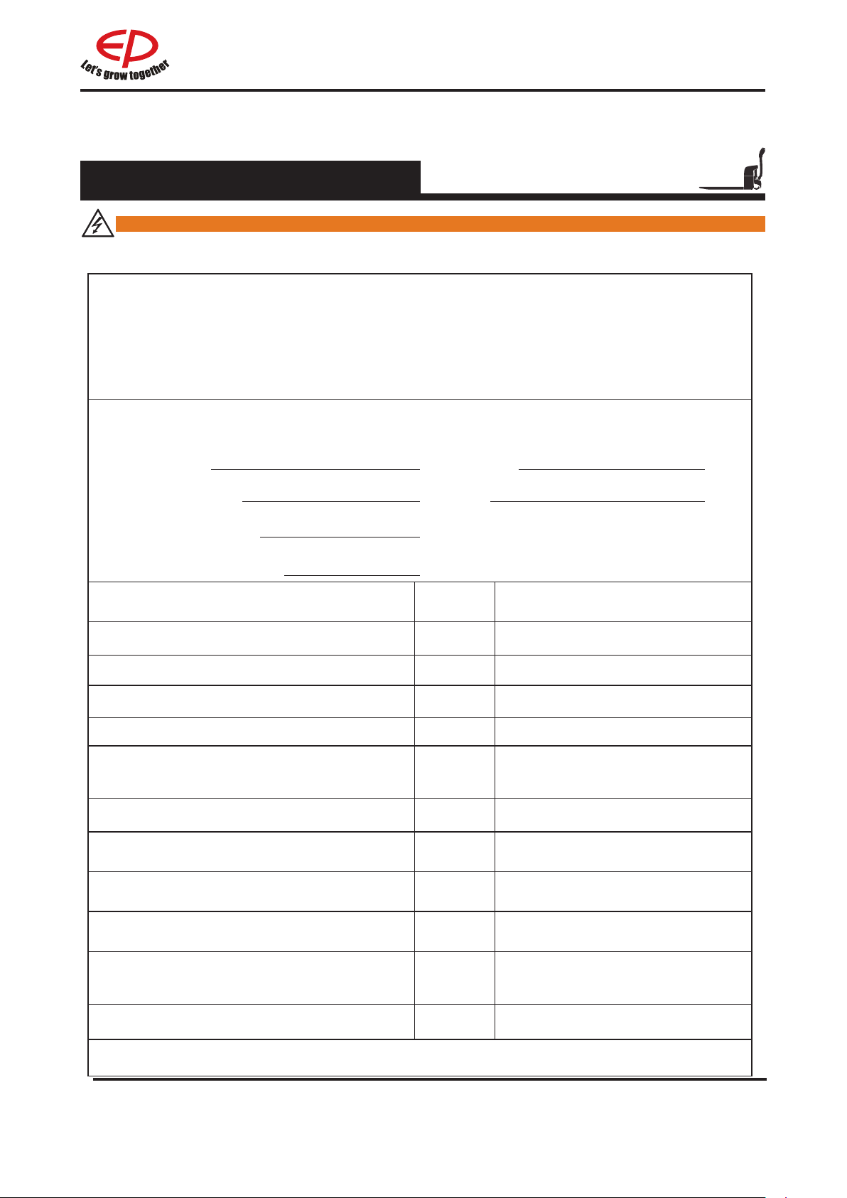
2.3 Truck use and operation
2.3.1 Preparation for use
WARNING
The following are inspection and preparation operations that must be implemented before the
truck is put into daily use.
Table 1. Table of daily inspections by operators
Operator's Daily Checklist
Date
Truck No.
Department
Runtime
Meter Reading
Daily Check Items O.K.(√) Remark
Check for Fluid Leakage
Check for scratches, deformation or cracks.
Check Decal Condition
Check the smooth movement of the wheels.
Check the function of the emergency brake
by activating the emergency stop switch.
Check, the tiller arm- switch braking function
Check the lifting and lowering functions by
operating the buttons.
Check if all bolts and nuts are tightened
rmly.
Check the vertical creep of the truck.(if
equipped)
Operator
No.
Check the
sure not to damage the battery cables.
Recharge the lithium-ion battery
lithium-ion
installation,
making
9
B
REV. 12/2019
Page 19

Table 1:
i
operators, and it can be adjusted according to specic requirements.
Table of Daily Inspections by Operators is only a sample table for the daily inspections of
WARNING
The truck should be regularly maintained by qualied maintenance engineers or technicians
that have passed the training of and also been authorized by the manufacturer.
NOTE
Precautions in the run-in period
After being put into use, the truck should operate under a low load at the initial stage and
satisfy the following requirements, especially before its operation time reaches 100h:
•Prevent the new storage battery from discharging excessively during its initial use.
•Implement complete preventive maintenance as specied.
•Avoid emergency braking, starting or swerving during the use of the truck.
•Implement oil uid replacement and lubrication before the time specied.
•Limit the loading weight at 70%-80% of the rated loading.
WARNING
Should it be necessary to repair the truck for any fault or the truck be found with any unsafe
condition, please immediately report to designated competent department, and please don’t
use the truck before potential faults or hazards are eliminated. All the repairs or adjustments
should be implemented under authorization, and all the services must be executed by
qualied maintenance technicians.
REV. 12/2019
10B
Page 20
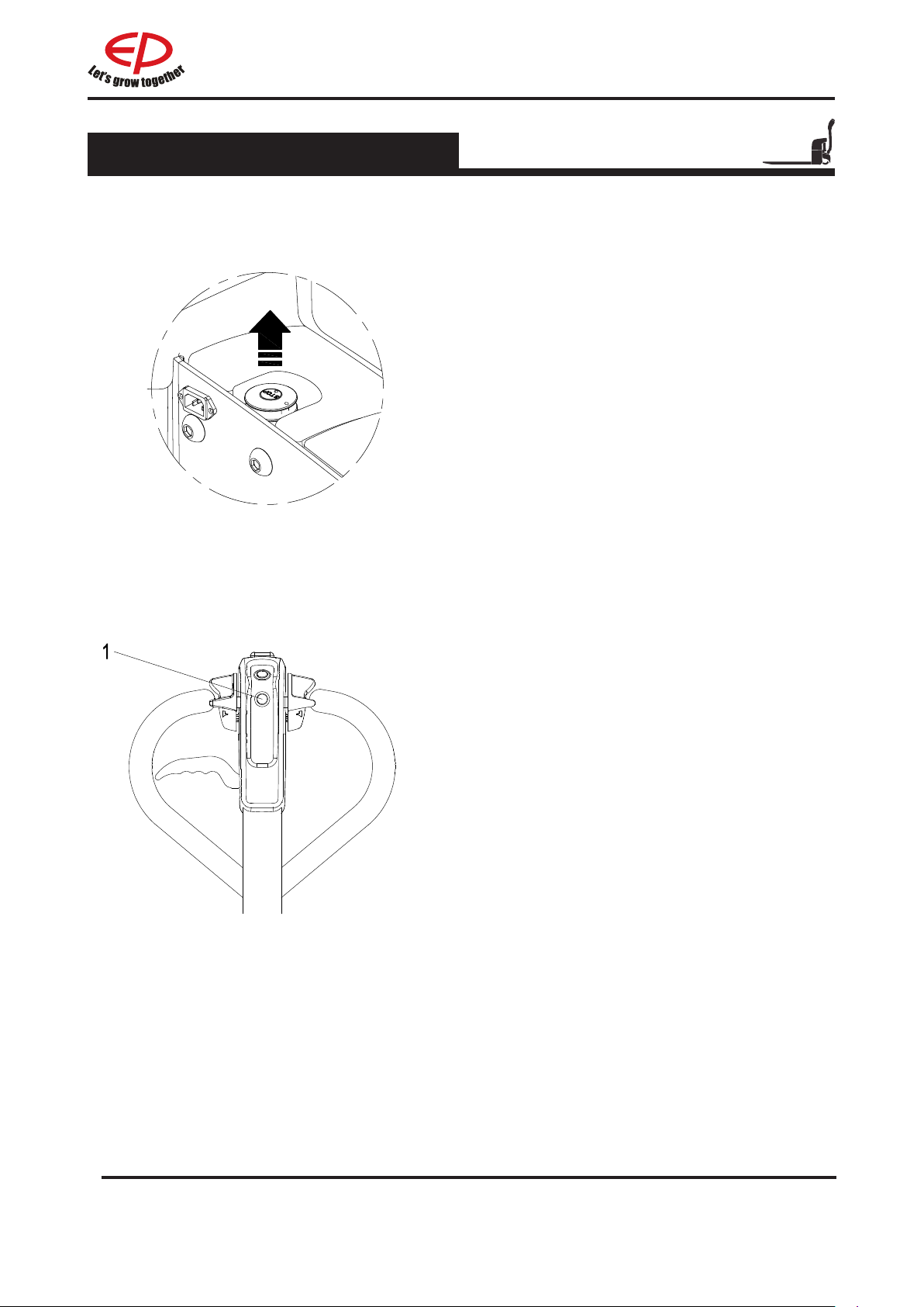
2.3.2 Truck starting
1. Release the emergency stop switch
2.Press the button to start the truck
HPL152
11
B
REV. 12/2019
Page 21
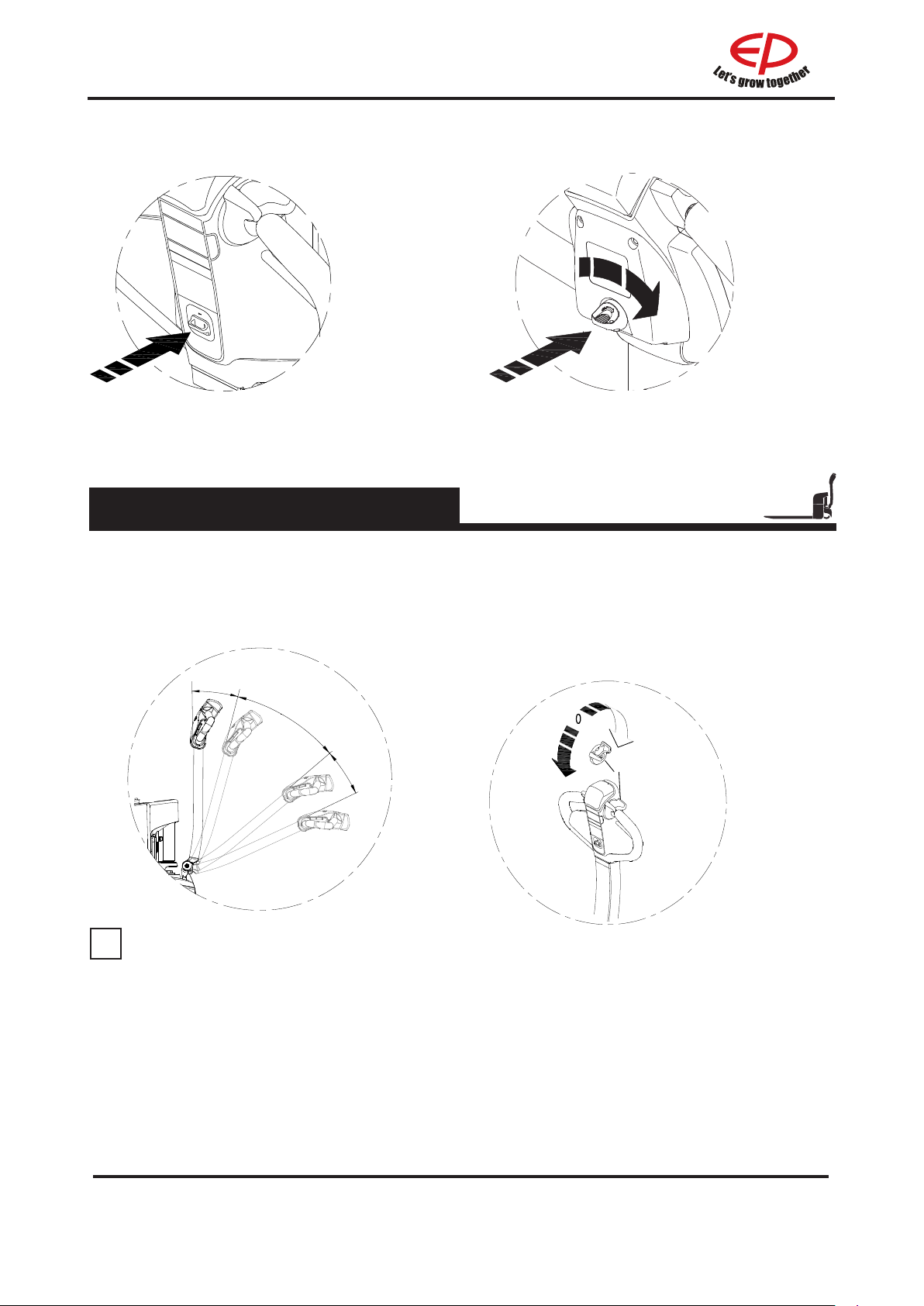
2.Open the key switch to start the truck
i
WPL201
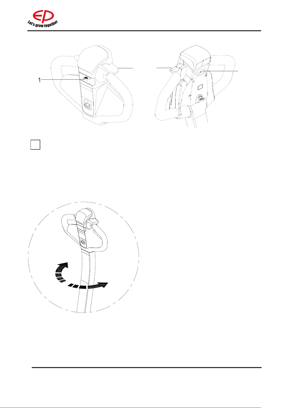
2.3.3 Running, swerving and braking
1.Running
Running area
Running area
RPL201/RPL201H/EPL151
Rotary button
Control the running direction and
speed of the truck using the drive
switch (1). (the large the rotary angle,
the faster corresponding speed)
Backward
1
Forward
NOTE
When using the truck on a ramp or a uneven road, please lift the leg of the forklift to prevent
its bottom from colliding with the road surface.
REV. 12/2019
12B
Page 22
1
2
i
WPL201 EPL151
2
NOTE
Keep the handle in the vertical state, and press tortoise speed button (1) and drive switch(2)
at the same time, then the vehicle will move at a low speed.
2.Swerving
Rotate the operation hand shank leftward or
rightward as required.
Rightward swerving
Leftward swerving
13
B
REV. 12/2019
Page 23
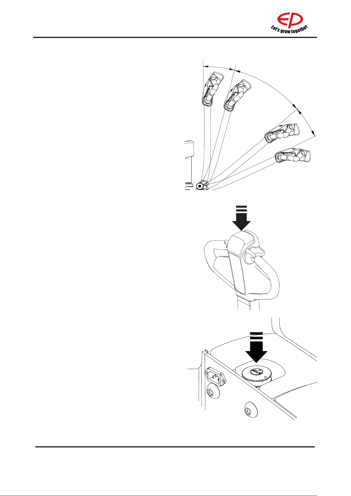
3.Braking
Mechanical operating brake
The truck is braked when the operating handle
is released.
The mechanical brake engages when the tiller
is positioned in Braking area.
Emegency reverse switch
Braking can be accomplished by changing
the direction of travel.
Press the reverse switch in the opposite
direction until the truck comes to a stop,
then release the drive switch.
Braking area
Braking area
Emergency stop switch
Press the emergency stop switch, and then
all the electrically propelled functions will be
interrupted.
REV. 12/2019
14B
Page 24
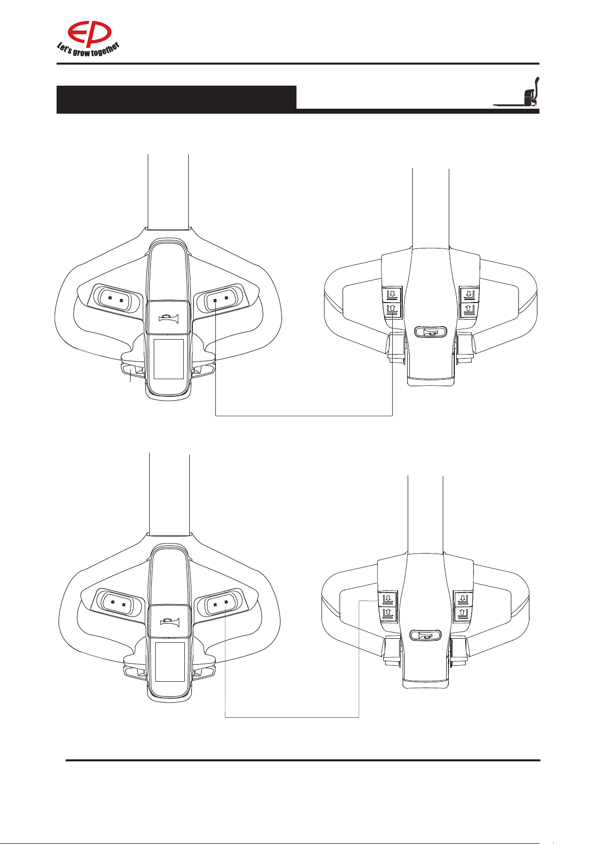
2.3.4 Goods picking
1.Lifting
2.Lowering
WPL201
RPL201/
RPL201H/
Keep pressing the lifting button until
reaching the required lifting height
EPL151
Lower the pallet forks to the bottom
through pressing the lowering button.
15
B
REV. 12/2019
Page 25
i
Lifting
Press lowering lever(2) to the bottom. Lift
the forks by moving the control shaft (1) up
and down until the desired lifting height is
achieved.Reset the lowering lever(2).
Lowering
Set forks to the lowest position by pulling
lowering lever(2) upward.
WARNING
Goods failing to be arranged and fixed
may result in accidents.
NOTE
To avoid shortening the service life of
the oil cylinder, try not to lift the pallet
forks to the highest state for every lifting
operation.
2.3.5
Parking the truck securely
Lower the forks to the bottom;
HPL152
REV. 12/2019
16B
Page 26
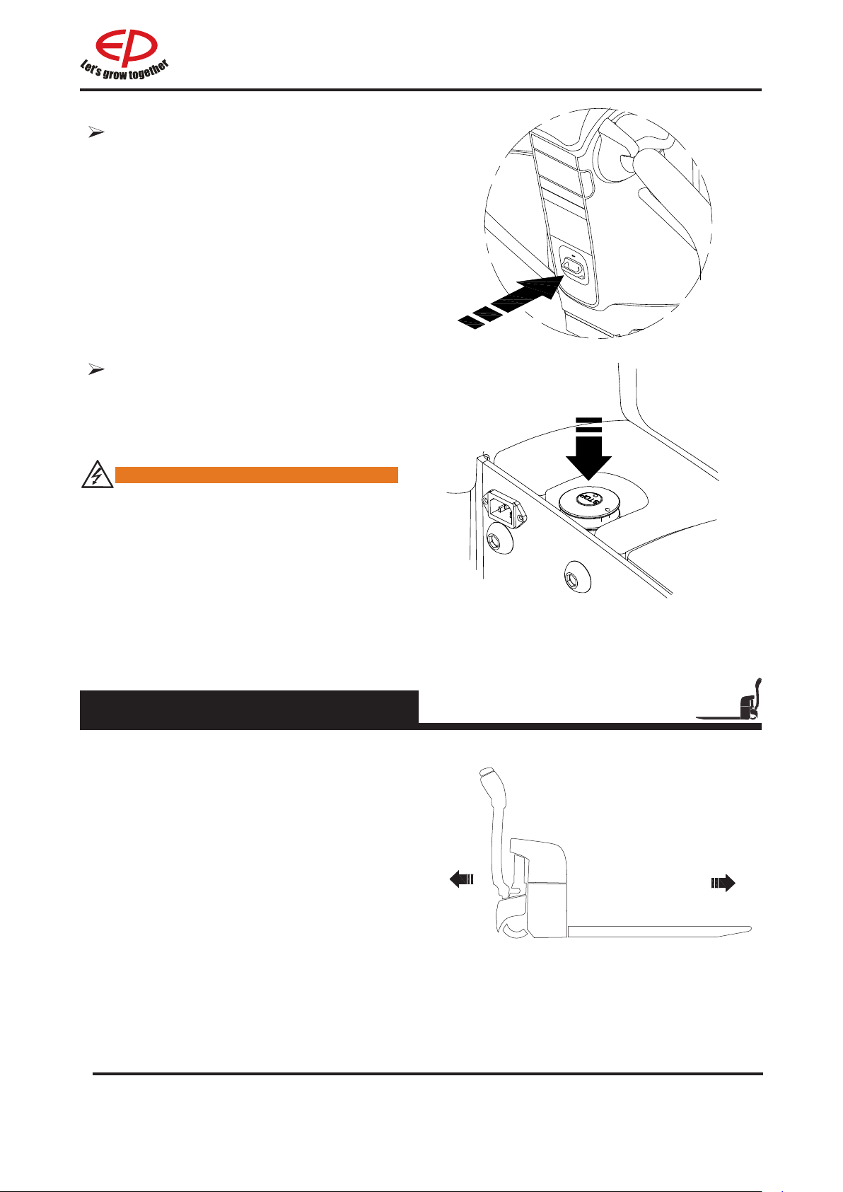
Turn o the key switch or pull out the
key;
Press the emergency stop switch to
cut o storage battery connection;
WARNING
•Should it be necessary for operators to
leave the truck, even for just a moment,
the truck should also be well parked as
specied.
•Never park the truck on a slope
•The forks must be lowered to the bott om.
;
2.3.6
The drive directions of the truck are forward (1)
and reverse (2).
Drive directions
1
17
B
2
REV. 12/2019
Page 27
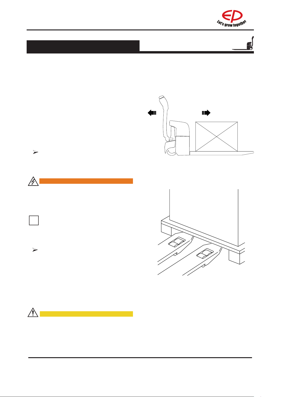
2.3.7 Loading
i
•
Approach the load carefully.
•
Adjust the height of the forks until they
can be easily inserted into the pallet.
•
Insert the forks under the load.
•
If the load is shorter than the forks,
position the forks so that the front of
the load overhangs them by a few
centimeters, to avoid interference with
the load immediately ahead.
•
Raise the load a few centimeters above
its support.
•
Back the truck away from the stack or
any neighbouring loads, gently and in a
straight line.
Transporting loads
Always carry loads in the forward
direction of travel (R) in order to have
the best visibility.
F
R
WARNING
When carrying a load on a slope, always
ascend or descend with the load uphill.
Never drive sideways across a slope or
perform a U-turn.
NOTE
Since visibility is reduced when travelling
in this direction, drive only at very slow
speed.
Unloading
Carefully drive the truck to the desired
location.
Carefully drive the truck to the unloading
area.
Lower the load until the fork arms are
free from the pallet.
Back the truck away in a straight line.
Raise the forks to proper height.
CAUTION
•If the eld of vision is poor, ask a guide
for assistance.
REV. 12/2019
18B
Page 28
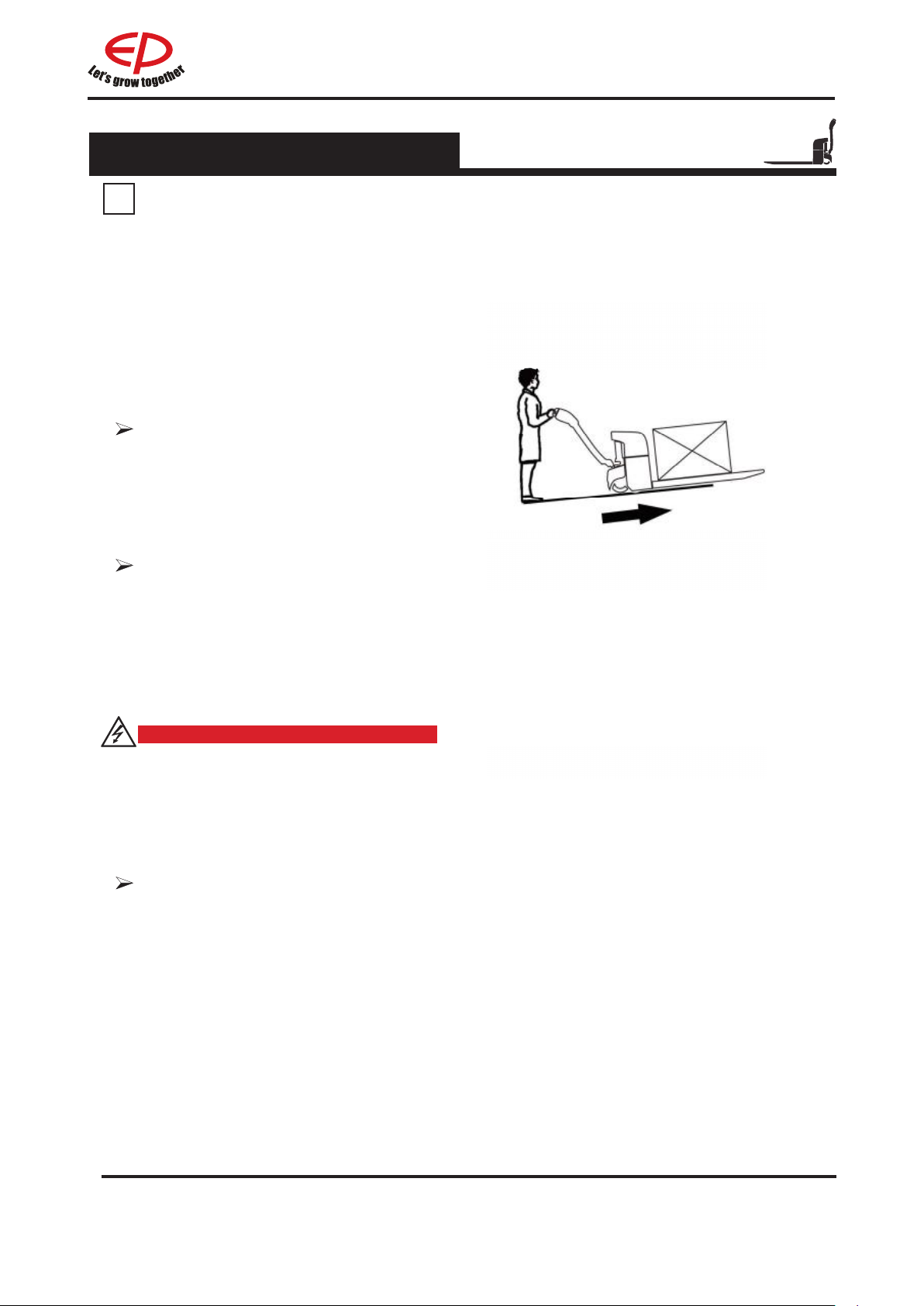
2.3.8 Using the truck on a slope
i
NOTE
Incorrect use of the truck on slopes
places stress on the traction motor,
brakes and battery.
Be particularly careful near slopes:
Never attempt a slope with a gradient
greater than that specied in the truck’s
data sheet. Make sure that the ground
is dry with a non-slip surface and that
the route is clear.
Ascending slopes
Always ascend slopes travelling in the
reverse direction, with the load facing
uphill. Without a load, it is recommend
to ascend slopes forwards.
Descending slopes
Travel down slopes must always be
forwards, with the load uphill. Without
a load, it is recommended to descend
slopes forwards. In all cases, travel at a
very low speed and brake very gradua-
lly.
DANGER
Risk to life and/or risk of major
equipment damage.
Never park the truck on a slope.
Never make a U-turn or take shortcuts
on a slope. On a slope, the operator
must drive very slowly.
Starting on a slope
If you have to stop and then start on
slope, proceed as follows:
•
Stop on the slope by pressing the
accelerator in the opposite direction
until the machine comes to a standstill.
•
Return the accelerator to the neutral
position, then release the accelerator
control button to apply the parking
brake.
•
To restart, press the accelerator button
for the desired direction.
•
The truck will move.
19
B
REV. 12/2019
Page 29
i
NOTE
i
Incorrect use of the truck on slopes
places stress on the traction motor,
brakes and battery.
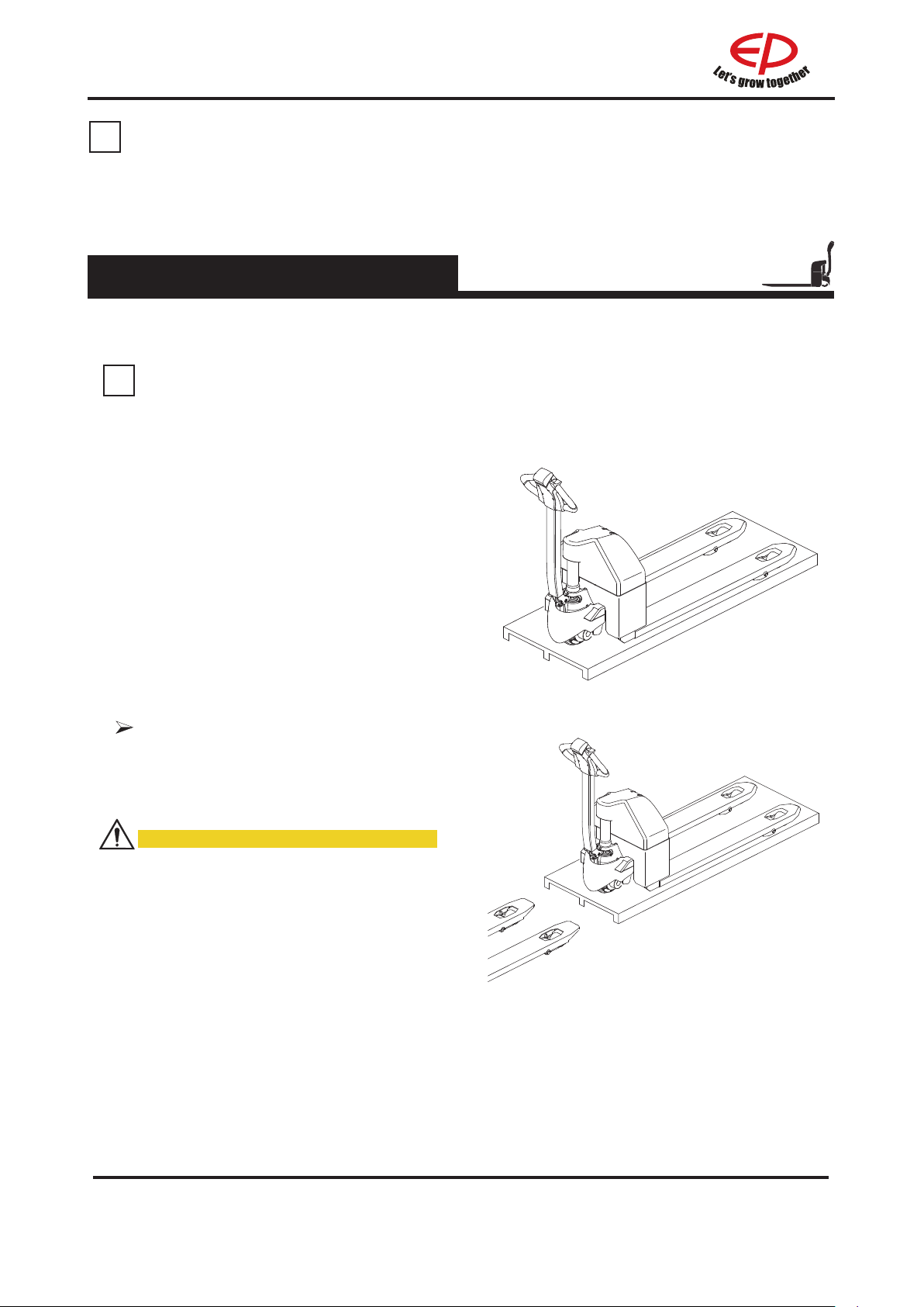
2.3.9 Truck transport
Place the truck on a wooden pallet.
NOTE
Only use haulage equipment with
sufcient load capacity.
•The load weight includes the net
weight of the truck(including battery
weight) and the wooden pallet.
•The pallet or wooden box should be
large and strong enough to withstand
the weightof the truck.
• Pay attention to the fork blades
when lifting the truck onto the pallet, to
prevent injuries caused by the forks.
Follow the prescribed steps and park
the vehicle correctly.
Make sure the forks are aligned with
the pallet, move slowly and stop after
inserting the forks as far into the
pallet as possible.
CAUTION
Operate on open, level ground and pay
attention to ground conditions when
lifting and lowering the pallet to prevent
the truck from tipping.
When transporting the truck, make
sure it is fully secured and take
precautionary measures against bad
weather.
REV. 12/2019
20B
Page 30
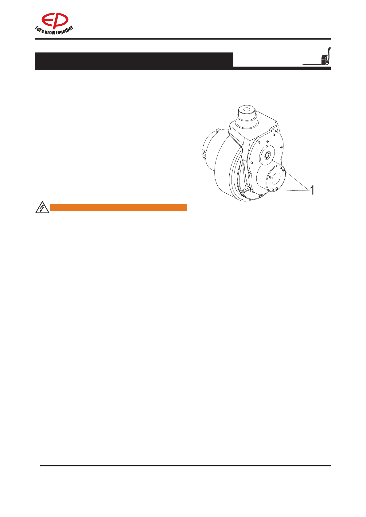
2.3.10 Operating the truck without its own drive system
If the truck has to be moved after a failure has
rendered it immobile, proceed as follows:
Set the emergency stop switch “OFF”.
Set the key switch “OFF” and remove the key.
•
Prevent the truck from rolling away.
•
Remove the cover.
•
Screw in two screws(1), M4*35mm)until the truck
can be moved (no braking action).
After setting down the truck at the destination,
unscrew two screws(1)
Braking action is restored.
.
WARNING
This operating mode is not permitted
when negotiating inclines and gradients.
21
B
REV. 12/2019
Page 31

C
Battery use and maintenance
3.1 Safety and warning
•Abide by the operation
manual!
•All the operations related
to the storage battery must
be implemented under the
instruction of professionals!
•Protective gloves must be
worn for storage battery
operation!
•No smoke and re!
•Avoid the existence of open
re, ery metal wire or sparks
around the storage battery,
otherwise explosion or re
disaster may occur!
•Don’t trample on the
storage battery to prevent
it from erce shaking or
shacking!
•Explosion or re disaster is
likely to occur; avoid short
circuit!
•Don’t knock over the storage
battery!
•Using lifting and delivery
devices as specied. Prevent
the storage battery cell,
interface and connection cable
from being damaged by the
lifting hook!
•Dangerous voltage!
•Avoid hot plugging!
•Notice: the metal part of
the storage battery cell is
electried, so don’t place any
external object or tool on the
battery cell!
Keep the battery away from all
re sources, heat sources and
ammable or explosive
materials.
Do not place the battery on
top of conductive objects.
WARNING
Should such issues as failing to abide
by the operation manual, failing to use
the original parts for maintenance or
damaging caused by users themselves
occur, the quality guarantee will be
invalid automatically!
Avoid the battery becoming
corroded by water or corrosive
liquid.
The charging environment
°C °C
5 - 40
1C
temperature should be 5°C to
40°C.
REV. 12/2019
Page 32
3.2 Battery charging
i
3.2.1 Precautions
•The truck must be parked within a shady and ventilated room;
•Avoid the existence of any metal object in the surface of the storage battery;
•All the cable and plug connection parts should be inspected in terms of obvious damages
before charging;
•The charger to be connected or disconnected must be under the state of not connecting
to the circuit;
•The safety provisions related to the storage battery and the manufacturer of charging
station must be strictly abode by.
Charging environment:
WARNING
Lithium battery must be charged above 0°C, as excessively low charging temperature is likely
to result in the short circuit of battery cell.
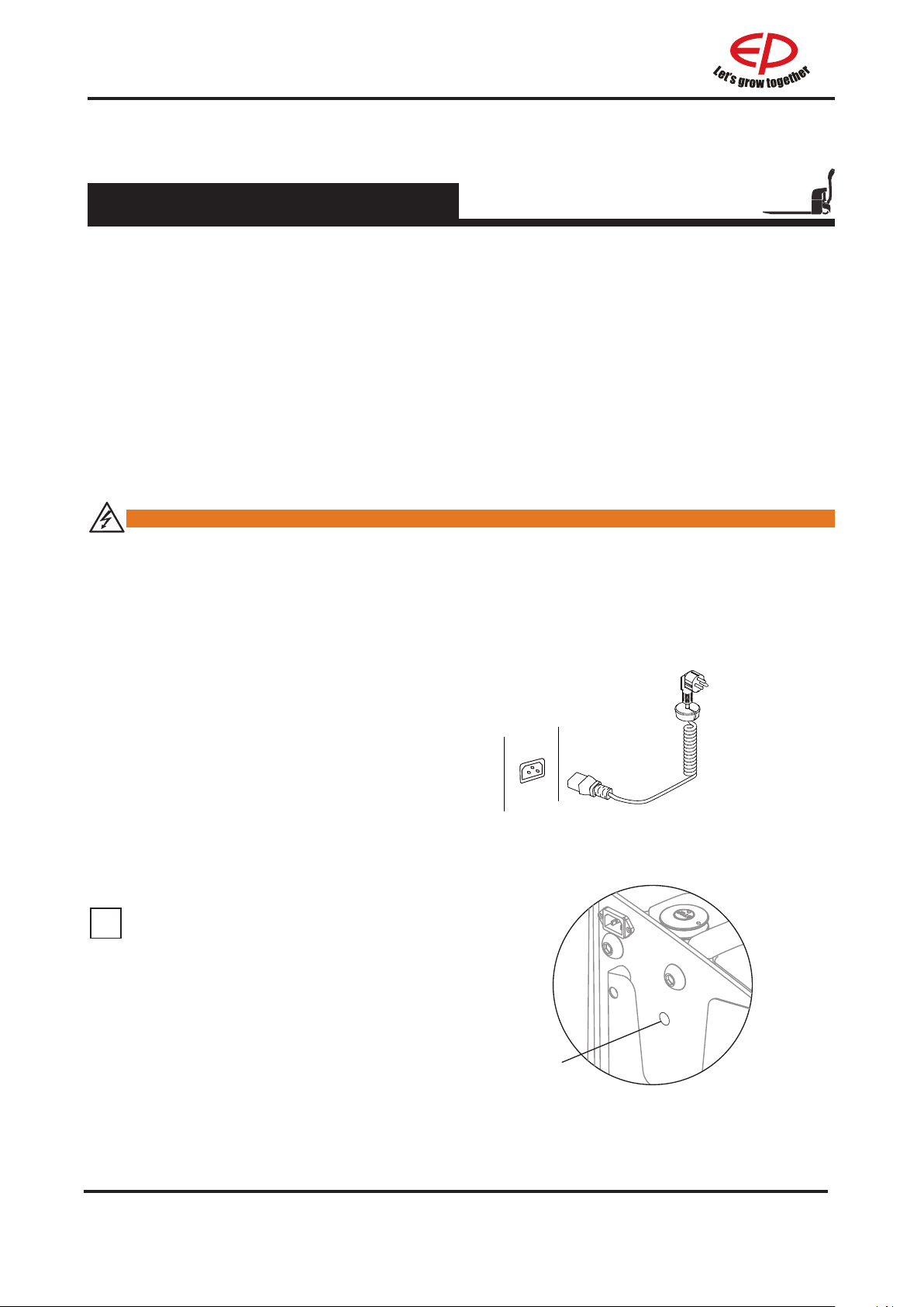
3.2.2 Charging the battery with internal charger
Charge maintenance-free or lithium battery
through a built-in charger
•Inspect whether relevant charging
requirements are satised according to
“3.2.1 precautions”;
Park the truck securely as described 2.3.5
•
Connect the specialized connector(1) to a
•
proper power supply outlet, then plug it into
the socket on the truck to start charging.
;
NOTE
The charging voltage is single-phase,
ranging from 100V to 240V, please don’t
exceed the voltage range mentioned
above.
power plug
WPL201/EPL151/HPL152
1
WPL201
REV. 12/2019
2C
Page 33
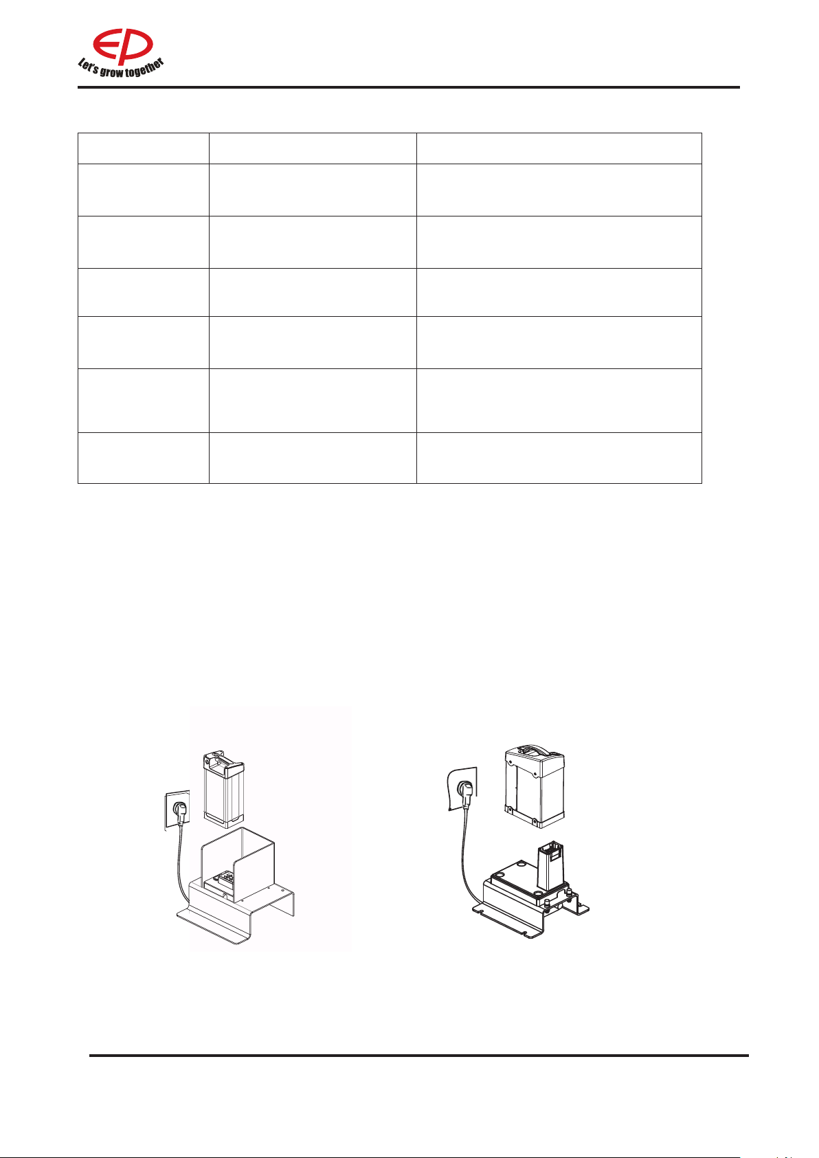
Charging indicator(1)
DISPLAY DESCRIPTION TROUBLESHOOTING
Continuous red
Continuous green
Continuous yellow
Flashing yellow
Flashing red
NO Lighting Charger failure
Battery is charging Normal status
Battery charging is complete Normal status
Battery failure
Charger failure
Charger without output
current
The battery voltage is less than 13V(26V)
or greater than 32.5V(65V). (for WPL201)
a. Output overcurrent or overvoltage
b. The temperature of charger is too high.
a. Charger failure.
b. The battery is not connected ;
c. battery failure.
a. Charger failure.
b. The input of charger is not connected.
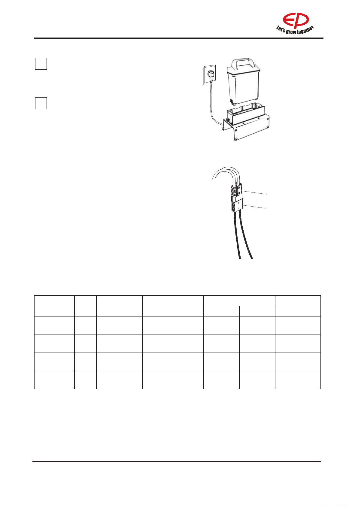
3.2.3 Charging the battery with external charger
•Inspect whether relevant charging requirements are satised according to “3.2.1
precautions”;
Park the truck securely as described 2.3.5;
•
Remove the battery;(see section 3.4)
•
Plug into charging stand and charge;
•
The LED light on the charging stand comes on.
•
A fully charging time see described in paragraph 3.2.4.
EPL151 WPL201
3C
REV. 12/2019
Page 34
i
i
NOTE
Correctly plug the battery into the charging
stand.
NOTE
LED light mode on the charging stand
• Charging:red LED light
• Fully charged:green LED light
• Charging fault:ashing yellow LED light
• Battery fault:steady yellow LED light
Charge the storage battery through an
external charger
•Inspect whether relevant charging
requirements are satised according to
“3.2.1 precautions”;
Park the truck securely as described 2.3.5
•
;
•Pull out the storage battery plug (1) and
have it connected with the charger joint
(2), so as to facilitate charging through
connecting to the charger.
HPL201
1
2
3.2.4 Battery type & dimensions&
All the batteries are maintenance free.
Battery types & dimensions are as follows:
Tuck type
WPL201
RPL201/
RPL201H
EPL151
HPL152 Li-ion 24/20AH 193x81x300
battery
type
Li-ion
Li-ion
Li-ion
Voltage/ Rated
capacity
48V/30Ah
24V/160Ah
24V/55Ah
Charging time
Dimensions
245×160×380 15A 15A 2h
550×190×500 / 50A/100A 3h/1.6h
175×124×407 10A 20A 5.5h/2.5h
RPL201/RPL201H
Charger
Charging time
Internal External
10A 10A 2h
REV. 12/2019
4C
Page 35

3.3 Handling of the lithium-ion battery
3.3.1 Information on the conformity of lithium-ion batteries
The manufacturer of the lithium-ion battery declares that: the lithium-ion battery
conforms with the provisions of the following EU directive 2014/30/EU
in accordance with EN12895.
This declaration of conformity with EU directives applies only to battery use that conforms to the
recommendations described in the operating instructions.
3.3.2 Special lithium-ion safety rules
DANGER
Have class D re extinguishers or inert gas, carbon dioxide, powder or foam re extinguishers
near the zone in which the lithium-ion batteries are used.
DANGER
Do not open the battery. Electrical risk. Only the After-Sales Service Centre technicians can
open the battery.
It is necessary to respect the following guidelines:
Read the documents provided with the battery carefully.
Only persons who have been trained to work with lithium-ion technology are permitted to work on
the batteries (for example After-Sales Service Centre technicians).
Do not place lithium-ion batteries on or near ames or hot heat sources (> 65°C). This may cause
the batteries to overheat or burst into ames. This type of use also impairs the performance of the
batteries and reduces their service life.
Improper use may cause overheating or serious injury. Respect the following safety rules:
• Never short circuit the battery terminals
• Do not reverse the battery polarity
• Do not open the battery
• Do not submit the battery to excessive mechanical constraints
• Do not expose the battery unit to humidity or water (> 80%)
5C
REV. 12/2019
Page 36

3.3.3
i
i
Transportation
Before transporting any lithium-ion battery, check the current
regulations on the transport of dangerous goods. Comply
with these when preparing the packaging and transport. Train
authorised sta to dispatch lithium-ion batteries.
NOTE
It is recommended that the original packaging is kept for
any subsequent dispatch.
A lithium-ion battery is a special product.
Special precautions should be taken when:
•
Transporting a truck equipped with a
lithium-ion battery
•
Transporting only the lithium battery
A class 9 danger label must be axed to the packaging for
transport.
It is dierent if the battery is transported on its own or in a
truck. An example of a label appears in this supplement.
Refer to the latest current regulations before dispatch as
the information might have changed since this supplement
was written.
Special documents must be sent with the battery. Refer to
the applicable standards or regulations.
NOTE
Recharge the lithium-ion battery before transporting it taking account of the transport mode
(plane, boat, road). Excessive discharge on arrival could damage the performance of the
battery.
3.3.4
Scrapping lithium-ion batteries
ENVIRONMENT NOTE
Comply with current regulations for scrapping batteries. Take care to minimise, as far as
possible, any impact on the environment.
Lithium-ion batteries must be sent to the collection centre to be recycled. Contact the
After-Sales Service Centre to agree how to send them.
Apply the following main rules for transport
Make sure that the battery is discharged
•
Ax the Class
•
Use packaging that complies with international regulations
•
•
Use the original packaging, if possible. Use sturdy packaging capable of bearing the weight
of the batteries. Store it in a dry place.
Wedge the battery well in the packaging to prevent it moving during transport
•
Pack batteries individually in plastic bags. Package them to prevent any risk of shortcircuit
•
between terminals.
Identify the type and number of batteries on the outside of the packaging
•
Do not store near to a heat source.
•
:
.
REV. 12/2019
6C
Page 37

3.3.5
Storage
We recommend that batteries are stored at a height between 60 and 120 cm.
•Store the battery in a dry place at a temperature between 0 and 40° to preserve its
service life. This area must not be hermetically sealed to allow air renewal;
•Check the battery charge level regularly. Do this at least every three months to
maintainthe charge level above 30%. Recharge the battery if necessary.
3.3.6
Common Problems and Solutions
During the use and maintenance of the lithium-ion battery, the battery or battery system may
have one or more of the following abnormal conditions, please organize the professional
engineers and technicians to perform the necessary processing according to the instructions
in this manual; if you have any questions about the status or solutions, please contact ep
dealer or after-sales service department of the company to obtain professional technical
support.
•
If the battery is found to have abnormal mechanical characteristics such as swelling, cracked
casing, melted casing, and distortion of the casing before and during installation, stop using
the battery immediately, place it in open and well-ventilated space, and contact the aftersales service.
•
If abnormalities such as looseness, cracks, cracks in the insulation layer, burn marks, etc.
of the battery's pole pressing bolts, conductive strips, main circuit wires and connectors are
found before and during the installation, stop using the battery immediately, check the reason
for analysis and give it a x;
•
If the polarity of the positive and negative terminals of the battery is found not match the
polarity identification before installation, please stop using the battery immediately and
contact the after-sales service department to replace the battery or obtain other solutions;
•
If there is re or smoke happens to the battery, move it to the open air immediately, evacuate
people in time, and pour a large amount of cold water onto the battery to cool it down and put
out the re.
•
If the battery is found to emit smoke before and during installation, immediately stop using
the battery and bury it with sand, and notify the after-sales service department of the
company for record and obtain technical support;
Disposal of Used Battery Packs
3.3.7
To prevent environmental pollution, the battery should be sent to a local recycling center or
special organization.
7C
REV. 12/2019
Page 38
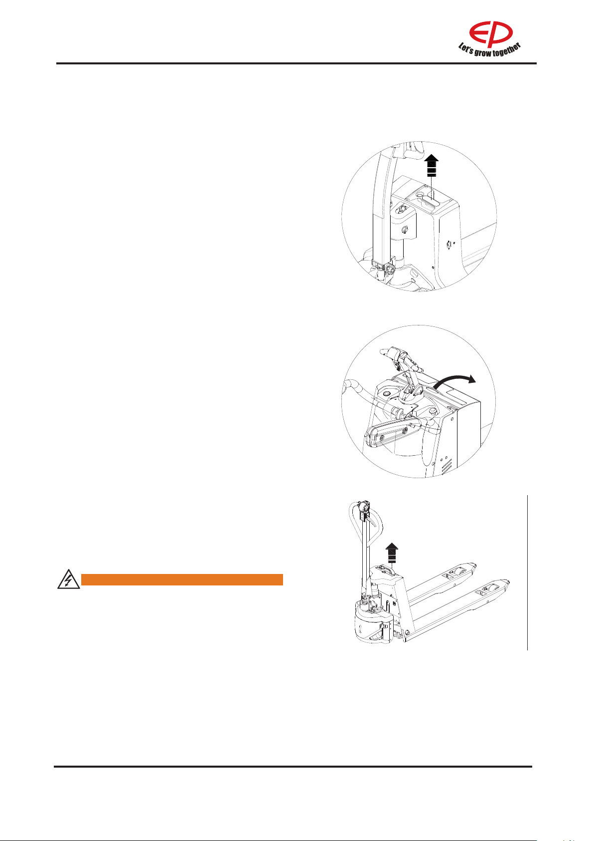
3.4 Battery removal and installation
Park the truck securely as descirbed in
paragraph 2.3.5 and turn o the power before
removal and installation of the battery.
Battery removal and installation steps:
Just hold the handle and pull the battery out.
•
Install in reverse order.
•
Open the battery cover;
•
Unplug the battery;
•
Attach the hooks to the battery handle or
•
strap;
Carefully lift the battery out of the truck;
•
Install the battery in reverse order.
•
WPL201, EPL151
Just hold the handle and pull the battery out.
•
Install in reverse order.
•
WARNING
Before removing the battery, make sure
the vehicle is completely powered o.
RPL201/RPL201H
HPL152
REV. 12/2019
8C
Page 39

Maintenance
D
Only through regularly implementing truck maintenance work can the sustainable and reliable use
of the forklift be ensured.
Only those receiving professional training and approved as qualied can be competent in various
equipment care maintenance operations. If you intend to independently implement maintenance,
you are recommended to have your maintenance personnel receive on-site training from the
service representative of the equipment supplier.
Safety announcement:
• Tyre replacement: please implement tire replacement using the tires designated by the
manufacturer, as unqualied tires may inuence the properties and stability of the products.
• It is improper to clean the truck using inammable liquid.
• Ensure that the power supply has been completely disconnected before actual maintenance
operation.
Long-term parking:
• If required to be parked for over one month, the truck must be placed in a dry and frost-free
environment.
• Clean the truck carefully.
• Coat any unpainted metal parts with a thin layer of oil or grease.
• In case that the truck is out of use for a long time, the storage battery should better be taken out.
• Recharge the lithium-ion battery every 2 months. Please observe the above instructions.
• Raise and chock the truck: the wheels must not touch the ground in order to prevent irreversible
deformation of the tyres.
4.1 Truck maintenance
Scrap treatment:
The nal scrap treatment of the forklift must be implemented according to the current laws and
•
regulations of China, especially the provisions related to such aspects as storage battery, fuels,
fuel oil and electric equipment
be recycled. Contact the After-Sales Service Centre to agree how to send them.
. Lithium-ion batteries must be sent to the collection centre to
REV. 12/2019
1D
Page 40

4.2 Maintenance table
Daily maintenance
1 Inspect and manipulate the functions of the Control handle’s manipulation
switches and the display instruments
2 Inspect the emergency outage function of the emergency stop switch or
the storage battery puller.
3 Inspect the swerving function.
4 Inspect the braking function
5 Inspect whether there is any abrasion or damage in the driving wheel/
load wheel/caster
6 Inspect whether there is any damage or abnormality in the truck.
7 Inspect whether the optional functions are under normal operation.
250-hour/2-month maintenance
8 Inspect where there is any damage in the cables and whether the
terminals are reliable
9 Inspect whether there is any screw losing or slipping out
10 Inspect whether there is any abrasion or damage in the oil pipes
11 Inspect where is any leakage in the hydraulic oil
500-hour/3-month maintenance
After operating for 500 hours in total, the truck should also be maintained according to the
following procedures in addition to the 250-hour maintenance mentioned above
12L
13L Inspect and lubricate using the lithium-based lubrication grease the
14 Inspect and lubricate using the lithium-based lubrication grease the
After operating for 1000 hours in total, the truck should also be maintained according to the
following procedures in addition to the 250-hour maintenance and 500-hour maintenance
mentioned above
15 Inspect and fasten the controller and other electrical apparatus elements
16 Inspect whether there is any abnormal sound or disclosure of the gear
17 Inspect the abrasion situations of the driving wheel/bearing wheel/
18 Inspect whether all the oil pipes, pipelines and joints are reliably
19L Inspect the level of the oil liquid, and if the level fails to reach the
20 Inspect the air gap of the electromagnetic brake, and if the air gap is
21 Inspect where is any abrasion or damage in the link mechanism
Inspect
lubrication mouths in moving parts
bearing between the driving engine and the gear box
box
universal wheel and please timely replace seriously abraded ones
connected and whether all the sealing elements are reliable
minimum one as required, please timely add hydraulic oil with the same
specications
larger than 0.4mm, please replace the friction plates.
or add the gear grease(for WPL201 and EPL151)
REV. 12/2019
D
2
Page 41
After operating for 1000 hours in total, the truck should also be maintained according to the
following procedures in addition to the 250-hour maintenance, 500-hour maintenance and 1000hour maintenance mentioned above
22
23L
24
25L
26
27
28 Inspect whether all the labels are clear and intact
Inspect the running, lifting and lowering speed, braking distance and other
operation performances of the truck Inspect and add gearbox lubrication grease
Inspect and replace gearbox gear oil (for RPL201/
Inspect where there is any damage in the oil cylinders and whether
corresponding installations are reliable
Clean the oil tank and replace the hydraulic oil
Inspect and replace the hydraulic lter
Inspect whether the bearing capacity reaches the rated load and implement
corresponding adjustment through the ood valve adopted in the hydraulic
station
HPL152
RPL201H、WPL201
)
WPL201
RPL201/RPL201H EPL151
EPL151/HPL152/WPL201
D
RPL201/RPL201H
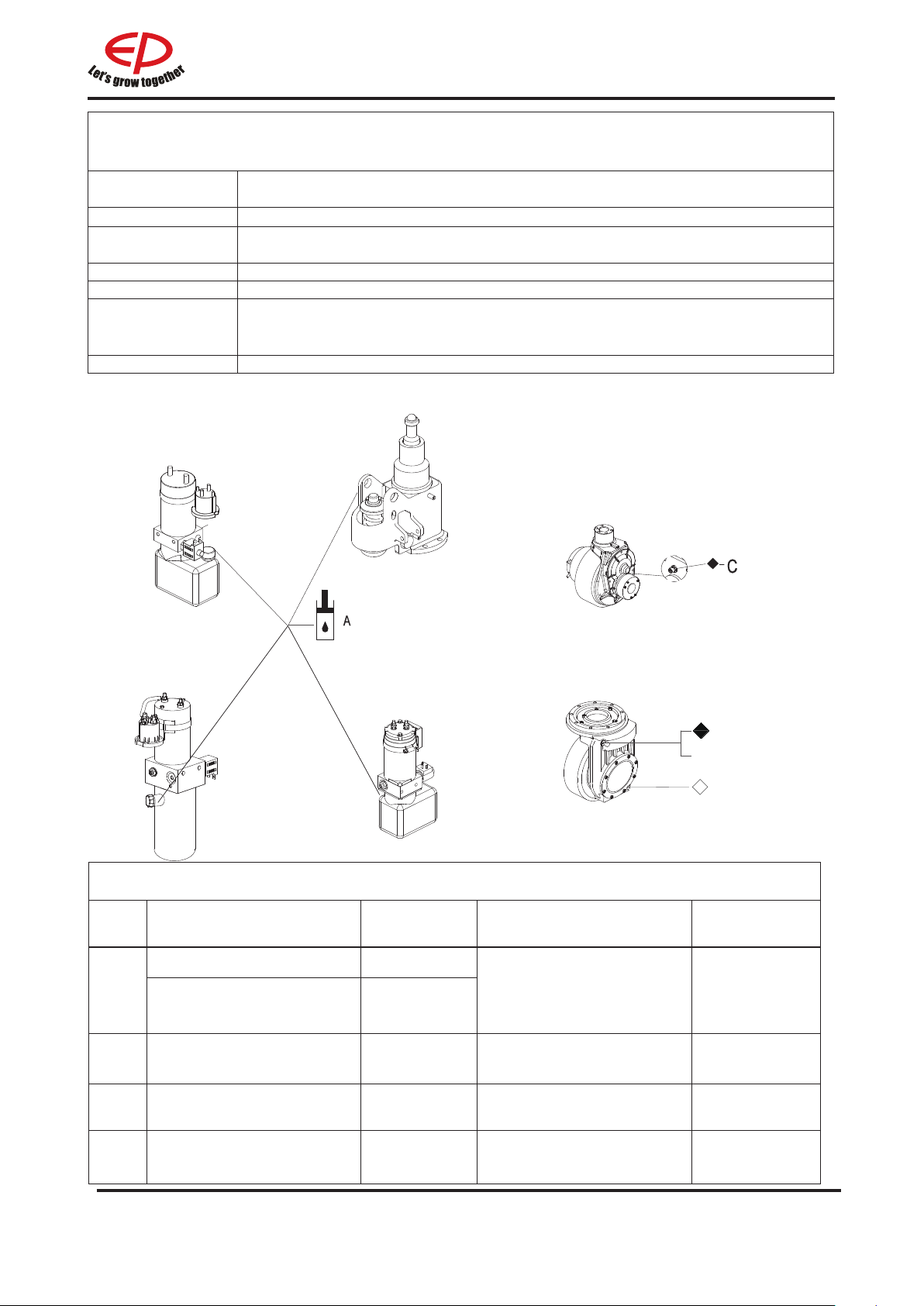
Table 1 Lubricants
Code Type Specication Amount Position
Anti-wear hydraulic oil L-HM32
A
Low temperature anti-wear
hydraulic oil (cold storage)
Multi-purpose grease
B
L-HV32
Polylub
GA352P
0.48 L((WPL201/EPL151
HPL152)1.25(RPL201
RPL201H)
Appropriate amount
/
/
Hydraulic
System
Sliding surface
(See Table 2)
Grease 3#(MoS2) -
C
Heavy duty gear oil 85W-90 GL-5 1500ml(RPL201/RPL201H) Gearbox
D
110 grams(EPL151/
HPL152/WPL201)
3D
Gearbox
REV. 12/2019
Page 42
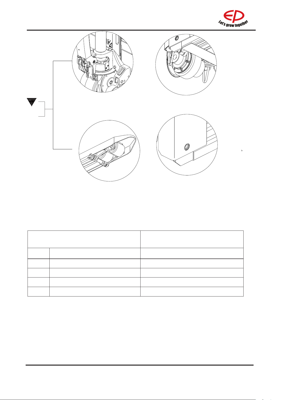
B
L1
L2
L3
Table 2 Sliding Surface
Lubrication Table
Code Position Model
L1 Steering Bearing
L2 Drive Wheel
L3 Load Wheel
L4 Long Shaft
L4
REV. 12/2019
D
4
Page 43

Technical data
E
Standard Version Specications
Technical specication details in accordance with VDI 2198. Technical modications and
additions reserved.
Performance data for standard trucks
Distinguishing mark
1.1 Manufacturer EP EP
1.2 Model
designation
1.3 Drive unit Electrics Electrics
1.4 Operator type Pedestrian Pedestrian
1.5 rated capacity Q kg 2000 2000
1.6 Load center
distance
1.8 Load distance x mm 1000 916/982 937/1003
1.9 Wheelbase y mm 1268 1418 1438
Weight
2.1 Service weight
(include battery)
2.2 Axle loading,
laden driving side/
loading side
2.3 Axle loading,
unladen driving
side/loading side
Types,Chassis
c mm 600 600
kg 250 630
kg 685/1565 1020/1610
kg 185/65 500/130
WPL201 RPL201
3.1 "Tyre type driving
wheels/loading
wheels"
Polyurethane Polyurethane
1
E
REV. 12/2019
Page 44

3.2 Tyre size, driving
wheels(diameter×width)
mm Ф250x102 Ф230x75
3.3 Tyre size, loading
wheels(diameter×width)
3.4 Tyre size, caster
mm 2×Ф82x85/
Ф82×115
Ф85x70 /
Ф83x115
mm Ф74x48 Ф130x60
wheels(diameter×width)
3.5 Wheels, number driving,
caster/loading (x=drive
mm 1×,2/4(1×
2/2)
1x,2/4(1x,2/2)
wheels)
3.6 Track width, front,driving
b10 mm 441 510
side
3.7 Track width,rear,loading
b11 mm 370/(515) 370/430/515
side
Dimensions
4.4 Lift height h3 mm 140 120
4.9 Height drawbar in driving
h14 mm 716 / 1240 1150 / 1470
position min./max.
4.15 Lowered height h13 mm 82.5 85
4.19 Overall length l1 mm 1592 1860 1930
4.20 Length to face of forks l2 mm 423 710
4.21 Overall width b1/ b2 mm 645 / 625 730
4.22 Fork dimensions s/ e/ l mm 55×170×1170 55x170x1150
55x170x1220
4.25 Distance between fork-
b5 mm 540(685) 540/600/685
arms
4.32 Ground clearance, center
m2 mm 27 30
of wheelbase
4.34.1 Aisle width for pallets 1000
Ast mm 1850 1984
× 1200 crossways
4.34.2 Aisle width for pallets 800
Ast mm 2050 2184
× 1200 lengthways
4.35 Turning radius Wa mm 1428 1700
Performance data
5.1 Travel speed, laden/
km/ h km/h 5 / 5.5 5.5 / 6
unladen
5.2 Lifting speed, laden/
m/ s 0.028/0.04 0.050 / 0.054
unladen
REV. 12/2019
E
2
Page 45

5.3 Lowering speed, laden/
unladen
fpm m / s0.04 / 0.022 0.067 / 0.054
5.8 Max. gradeability, laden/
% 8 / 16 8 / 16
unladen
5.10 Service brake type Electromagnetic Electromagnetic
Electric-engine
6.1 Drive motor rating S2 60
hp kW 0.75 1.5
min
6.2 Lift motor rating at S3 15% hp kW 0.84 2.2
6.3 The maximum allowed size
in. mm 245×160×380 550*190*500
battery
6.4 Battery voltage/nominal
V/ Ah 48/30(Li-ion) 24 / 160
capacity K5
6.5 Battery weight lb. kg 14 70
Addition data
8.1 Type of drive control DC AC
10.5 Steering type mechanical electronic
10.7 Sound pressure level at
the driver’s ear
dB (A) <74 <74
3
E
REV. 12/2019
Page 46
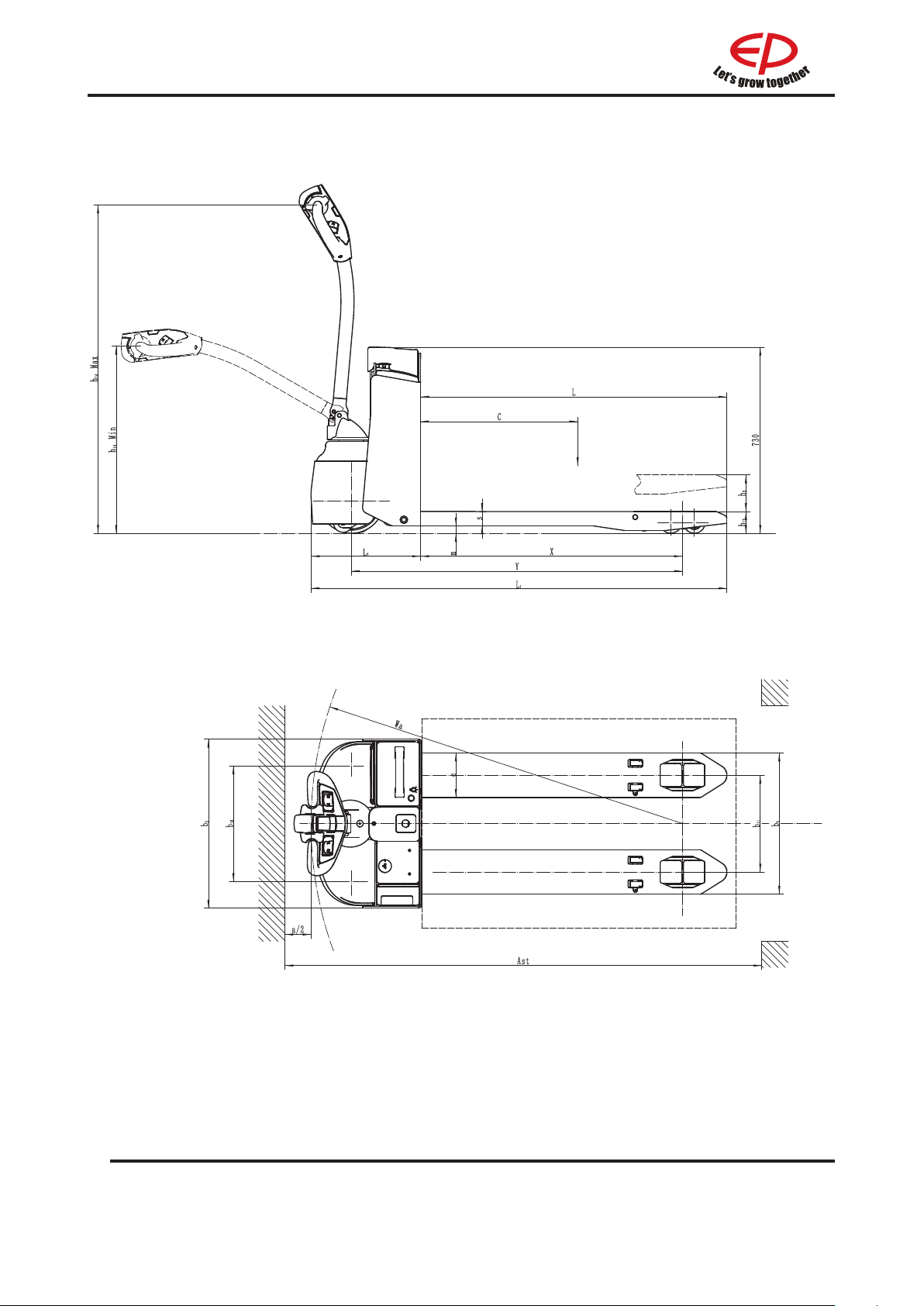
WPL201
REV. 12/2019
E
4
Page 47
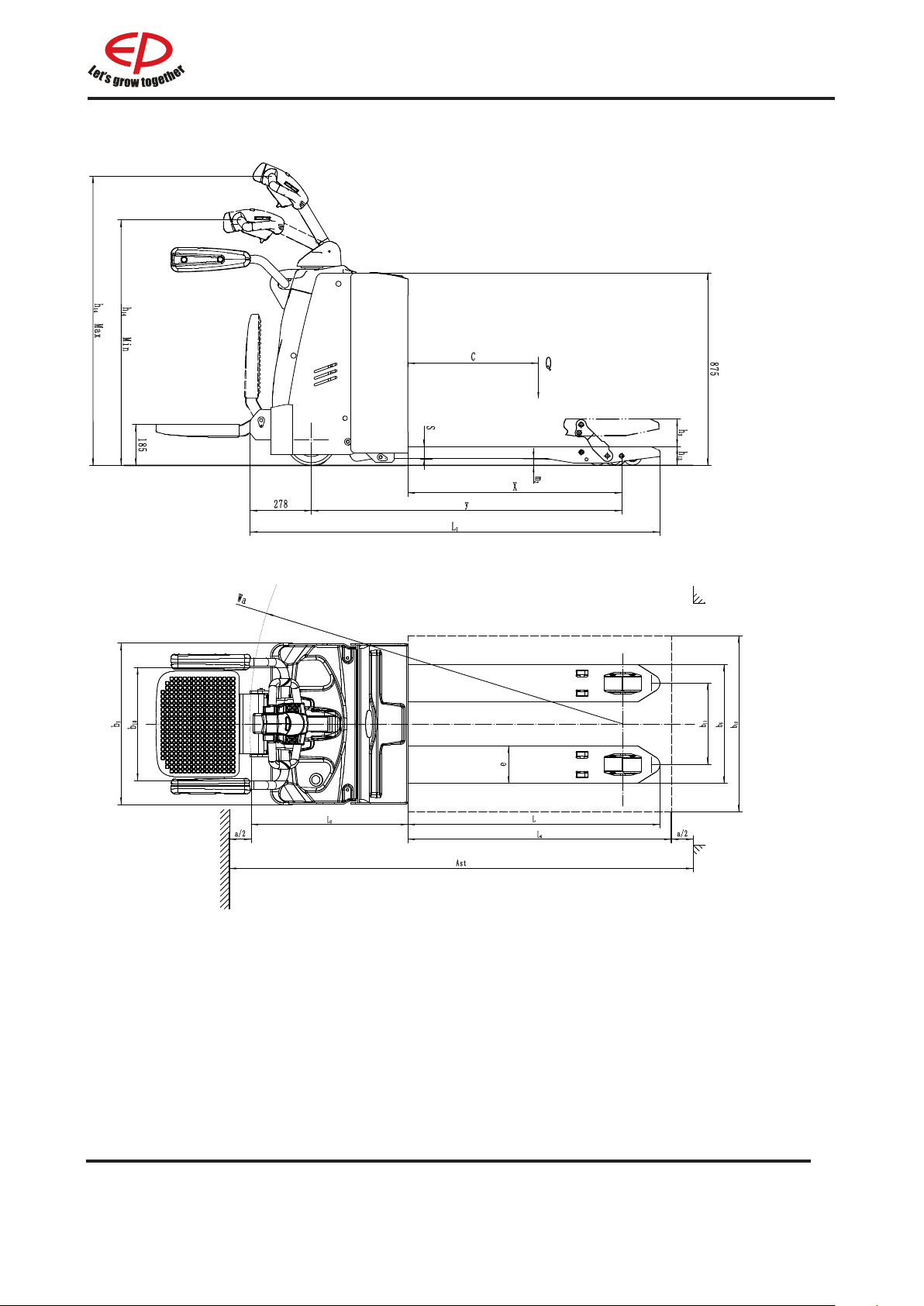
RPL201/RPL201H
5
E
REV. 12/2019
Page 48

Distinguishing mark
1.1 Manufacturer EP EP
1.2 Model
EPL151 HPL152
designation
1.3 Drive unit Electrics Electrics
1.4 Operator type Pedestrian Pedestrian
1.5 rated capacity Q kg 1500 1500
1.6 Load center
c mm 600 600
distance
1.8 Load distance x mm 883/946 883/946
1.9 Wheelbase y mm 1105/1168 1105/1168
Weight
2.1 Service weight
kg 165 130
(include battery)
2.2 Axle loading,
kg 574/1091 558/1172
laden driving side/
loading side
2.3 Axle loading,
kg 130/35 84/46
unladen driving
side/loading side
Types,Chassis
3.1 "Tyre type driving
wheels/loading
wheels"
REV. 12/2019
PU/ PU PU/ PU
E
6
Page 49

3.2 Tyre size, driving
wheels(diameter×width)
mm Ф210x70 Ф210x70
3.3 Tyre size, loading
wheels(diameter×width)
3.4 Tyre size, caster
mm 2x Ф78x60
(Ф78x88)
mm Ф74x48 /
2x Ф78x60
(Ф78x88)
wheels(diameter×width)
3.5 Wheels, number driving,
mm 1×,2/4(1× 2/2) 1x,4(1x,2)
caster/loading (x=drive
wheels)
3.6 Track width, front,driving
b10 mm 438 /
side
3.7 Track width,rear,loading
b11 mm 390 390
side
Dimensions
4.4 Lift height h3 mm 115 115
4.9 Height drawbar in driving
h14 mm 700 / 1170 638/ 1275
position min./max.
4.15 Lowered height h13 mm 80 80
4.19 Overall length l1 mm 1523 1518
4.20 Length to face of forks l2 mm 375 381
4.21 Overall width b1/ b2 mm 600 548
4.22 Fork dimensions s/ e/ l mm 50/150/1150 50/150/1150
4.25 Distance between fork-
b5 mm 540 540
arms
4.32 Ground clearance, center
m2 mm 30 30
of wheelbase
4.34.1 Aisle width for pallets 1000
Ast mm 1584 1612
× 1200 crossways
4.34.2 Aisle width for pallets 800
Ast mm 1784 1812
× 1200 lengthways
4.35 Turning radius Wa mm 1330 1358
Performance data
5.1 Travel speed, laden/
km/ h km/h 4/4.5 3.5/4
unladen
5.2 Lifting speed, laden/
unladen
m/ s 0.022/0.025 100mm/per
time
7
E
REV. 12/2019
Page 50

5.3 Lowering speed, laden/
unladen
fpm m / s0.034/0.023 Hand down
5.8 Max. gradeability, laden/
% 5/16 5 / 10
unladen
5.10 Service brake type Electromagnetic Electromagnetic
Electric-engine
6.1 Drive motor rating S2 60
hp kW 0.65 0.75
min
6.2 Lift motor rating at S3 15% hp kW 0.8 man-up
6.3 The maximum allowed size
in. mm 175*124*407 193*81*300
battery
6.4 Battery voltage/nominal
V/ Ah 24V*1/40Ah 24 / 20AH
capacity K5
6.5 Battery weight lb. kg 13*1 5*1
Addition data
8.1 Type of drive control DC DC
10.5 Steering type mechanical mechanical
10.7 Sound pressure level at
dB (A) <74 <74
the driver’s ear
REV. 12/2019
E
8
Page 51
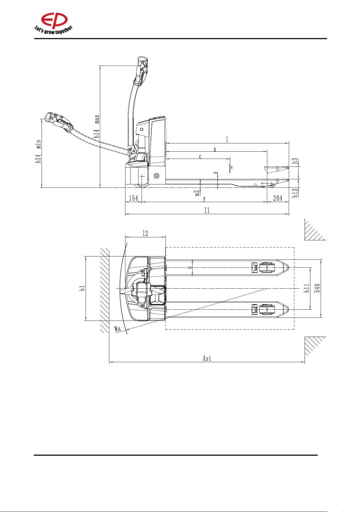
EPL151
9
E
REV. 12/2019
Page 52
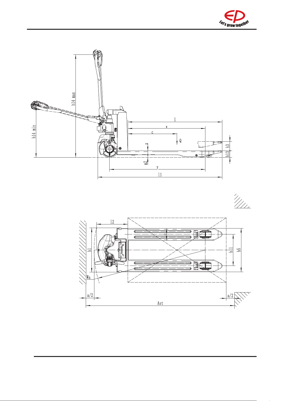
HPL152
REV. 12/2019
E
10
 Loading...