

Page 1
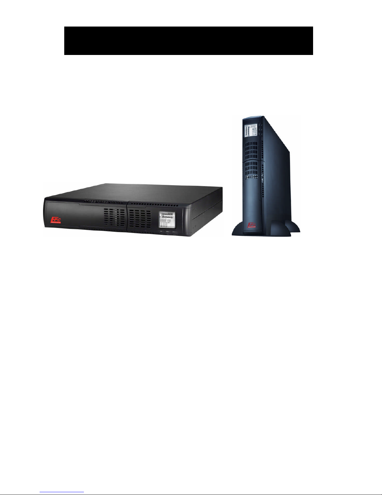
Model EOTL
800/1.1K/1.5K/2K/2.5K/3K VA
Interactive UPS Pure Sine Wave
Uninterruptible Power Supply System
User Manual
Page 2

1
Table of Contents
1. Important Safety Warning……………………………………………… 2
1-1. Transportation 2
1-2. Preparation 2
1-3. Installation 2
1-4. Operation 2
1-5. Maintenance, Service And Faults 3
2. Installation And Setup…………………………………………………… 4
2-1. Rear Panel View 4
2-2. Install The UPS 5
2-3. Setup The UPS 6
2-4. Battery Replacement 7
3. Operations………………………………………………………………….. 8
3-1. Button Operation 8
3-2. LCD Panel 8
3-3. Audible Alarm 9
3-4. LCD Display Wordings Index 10
3-5. UPS Setting 10
3-6. Operating Mode Description 12
3-7. Faults Reference Code 12
3-8. Warning Indicator 13
4. Troubleshooting…………………………………………………………... 14
5. Storage And Maintenance………………………………………………. 16
6. Specifications……………………………………………………………… 17
Page 3

2
1. Important Safety Warning
Please comply with all warnings and operating instructions in this manual strictly. Save this
manual properly and read carefully the following instructions before installing the unit. Do not
operate this unit before reading through all safety information and operating instructions
carefully
1-1. Transportation
Please transport the UPS system only in the original package to protect against shock
and impact.
1-2. Preparation
Condensation may occur if the UPS system is moved directly from cold to warm
environment. The UPS system must be absolutely dry before being installed. Please
allow at least two hours for the UPS system to acclimate the environment.
Do not install the UPS system near water or in moist environments.
Do not install the UPS system where it would be exposed to direct sunlight or near
heater.
Do not block ventilation holes in the UPS housing.
1-3. Installation
Do not connect appliances or devices which would overload the UPS system (e.g.
laser printers) to the UPS output sockets.
Place cables in such a way that no one can step on or trip over them.
Do not connect domestic appliances such as hair dryers to UPS output sockets.
The UPS can be operated by any individuals with no previous experience.
Connect the UPS system only to an earthed shockproof outlet which must be easily
accessible and close to the UPS system.
Please use only VDE-tested, CE-marked mains cable (e.g. the mains cable of your
computer) to connect the UPS system to the building wiring outlet (shockproof
outlet).
Please use only VDE-tested, CE-marked power cables to connect the loads to the UPS
system.
When installing the equipment, it should ensure that the sum of the leakage current
of the UPS and the connected devices does not exceed 3.5mA.
1-4. Operation
Do not disconnect the mains cable on the UPS system or the building wiring outlet
(shockproof socket outlet) during operations since this would cancel the protective
earthing of the UPS system and of all connected loads.
The UPS system features its own, internal current source (batteries). The UPS output
sockets or output terminals block may be electrically live even if the UPS system is not
connected to the building wiring outlet.
In order to fully disconnect the UPS system, first press the OFF/Enter button to
disconnect the mains.
Prevent no fluids or other foreign objects from inside of the UPS system.
Page 4

3
1-5. Maintenance, Service And Faults
The UPS system operates with hazardous voltages. Repairs may be carried out only
by qualified maintenance personnel.
Caution - risk of electric shock. Even after the unit is disconnected from the mains
(building wiring outlet), components inside the UPS system are still connected to the
battery and electrically live and dangerous.
Before carrying out any kind of service and/or maintenance, disconnect the batteries
and verify that no current is present and no hazardous voltage exists in the terminals
of high capability capacitor such as BUS-capacitors.
Only persons are adequately familiar with batteries and with the required
precautionary measures may replace batteries and supervise operations.
Unauthorized persons must be kept well away from the batteries.
Caution - risk of electric shock. The battery circuit is not isolated from the input
voltage. Hazardous voltages may occur between the battery terminals and the
ground. Before touching, please verify that no voltage is present!
Batteries may cause electric shock and have a high short-circuit current. Please take
the precautionary measures specified below and any other measures necessary when
working with batteries:
-remove wristwatches, rings and other metal objects
-use only tools with insulated grips and handles.
When changing batteries, install the same number and same type of batteries.
Do not attempt to dispose of batteries by burning them. This could cause battery
explosion.
Do not open or destroy batteries. Escaping electrolyte can cause injury to the skin
and eyes. It may be toxic.
Please replace the fuse only with the same type and amperage in order to avoid fire
hazards.
Do not dismantle the UPS system.
Page 5
4
2. Installation And Setup
NOTE: Before installation, please inspect the unit. Be sure that nothing inside the package is
damaged. Please keep the original package in a safe place for future use.
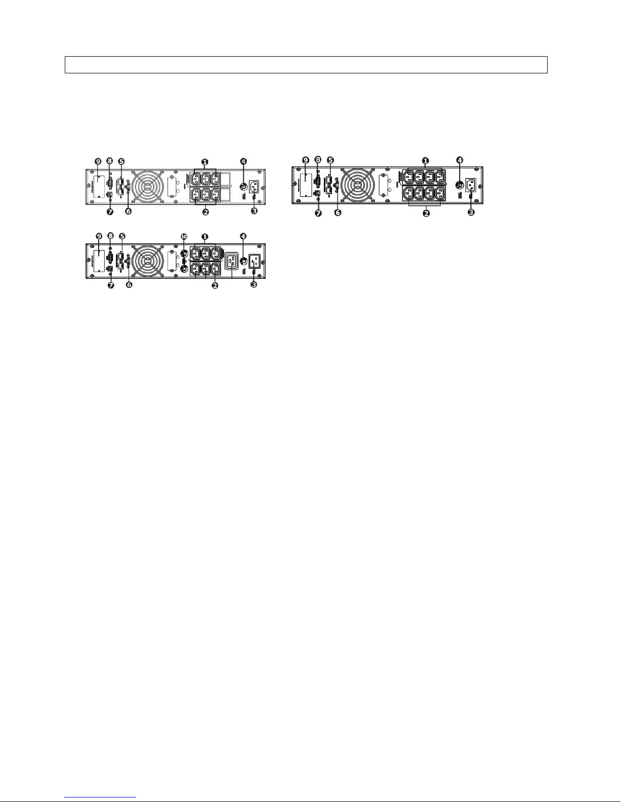
2-1. Rear Panel View
800/1.1K 1.5K/2K
2.5K/3K
1. Programmable outlets: connect to non-critical loads.
2. Output receptacles: connect to mission-critical loads.
3. AC input
4. Input circuit breaker
5. Network/Fax/Modem surge protection
6. Emergency power off function connector (EPO)
7. USB communication port
8. RS-232 communication port
9. SNMP intelligent slot
10.Output circuit breaker
Page 6
5
2-2. Install The UPS
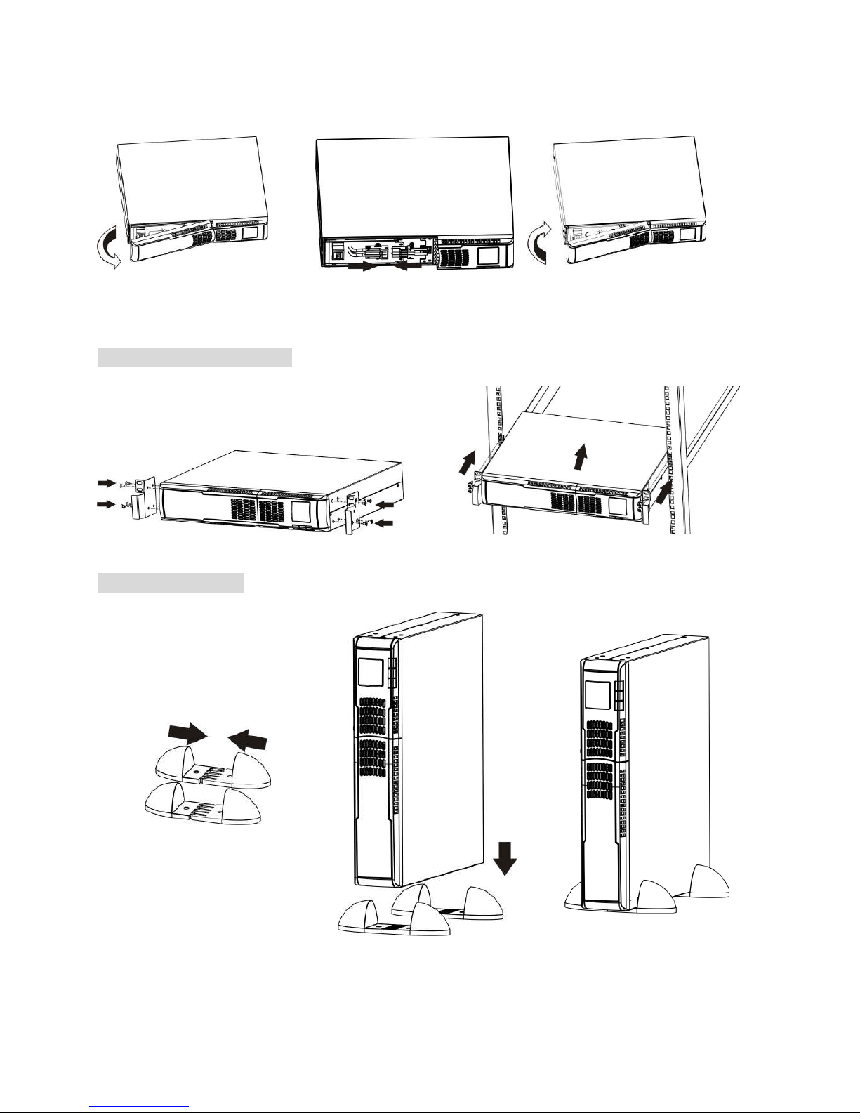
For safety consideration, the UPS is shipped out from factory without connecting battery wires.
Before install the UPS, please follow below steps to re-connect battery wires first.
Step 1 Step 2 Step 3
Remove front panel. Re-connect battery wires. Put the front panel back to the
unit.
Rack-mount Installation
Step 1 Step 2
Tower Installation
Step 1 Step 2 Step 3
Page 7
6
2-3. Setup The UPS
Step 1: UPS input connection
Plug the UPS into a two-pole, three-wire, grounded receptacle only. Avoid using extension
cords.
Step 2: UPS output connection
For socket-type outputs, there two kinds of outputs: programmable outlets and general
outlets. Please connect non-critical devices to the programmable outlets and critical
devices to the general outlets. During power failure, you may extend the backup time to
critical devices by setting shorter backup time for non-critical devices.
Step 3: Communication connection
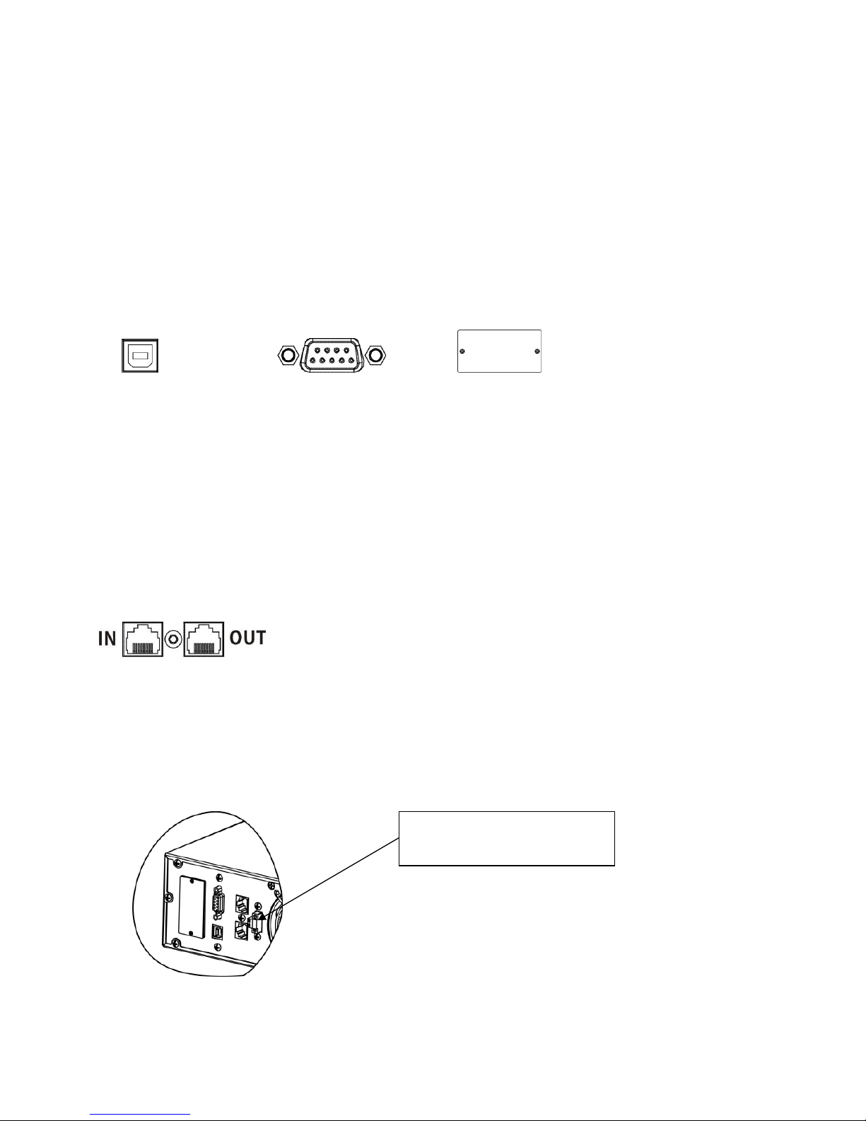
Communication port:
USB port RS-232 port Intelligent slot
To allow for unattended UPS shutdown/start-up and status monitoring, connect the
communication cable one end to the USB/RS-232 port and the other to the communication
port of your PC. With the monitoring software installed, you can schedule UPS
shutdown/start-up and monitor UPS status through PC.
The UPS is equipped with intelligent slot perfect for either SNMP or AS400 card. When
installing either SNMP or AS400 card in the UPS, it will provide advanced communication and
monitoring options.
PS. USB port and RS-232 port can’t work at the same time.
Step 4: Network connection
Network/Fax/Phone surge port
Connect a single modem/phone/fax line into surge-protected “IN” outlet on the back panel of
the UPS unit. Connect from “OUT” outlet to the equipment with another modem/fax/phone line
cable.
Step 5: Disable and enable EPO function
Keep the pin 1 and pin 2 closed for UPS normal operation. To activate EPO function, cut the
wire between pin 1 and pin 2.
It’s in closed status for UPS
normal operation.
Page 8
7
Step 6: Turn on the UPS
Press the ON/Mute button on the front panel for two seconds to power on the UPS.
Note: The battery charges fully during the first five hours of normal operation. Do not
expect full battery run capability during this initial charge period.
Step 7: Install software
For optimal computer system protection, install UPS monitoring software to fully configure UPS
shutdown. Please follow steps below to download and install monitoring software:
1. Go to the website http://www.power-software-download.com
2. Click ViewPower software icon and then choose your required OS to download the software.
3. Follow the on-screen instructions to install the software.
4. When your computer restarts, the monitoring software will appear as an orange plug icon
located in the system tray, near the clock.
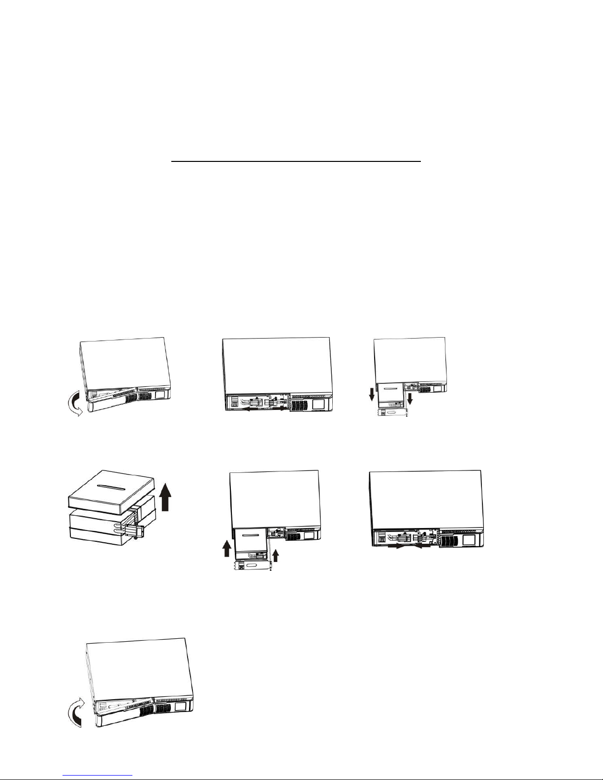
2-4 Battery Replacement
NOTICE: This UPS is equipped with internal batteries and user can replace the batteries
without shutting down the UPS or connected loads.(hot-swappable battery design)
Replacement is a safe procedure, isolated from electrical hazards.
CAUTION!! Consider all warnings, cautions, and notes before replacing batteries.
Note: Upon battery disconnection, equipment is not protected from power outages.
Step 1 Step 2 Step 3
Remove front panel. Disconnect battery wires. Pull out the battery box by
removing two screws on the
front panel.
Step 4 Step 5 Step 7
Remove the top cover of
battery box and replace the
inside batteries.
After replacing the
batteries, put the battery
box back to original location
and screw it tightly.
Re-connect the battery wires.
Step 8
Put the front panel back to the unit.
Page 9
8
3. Operations
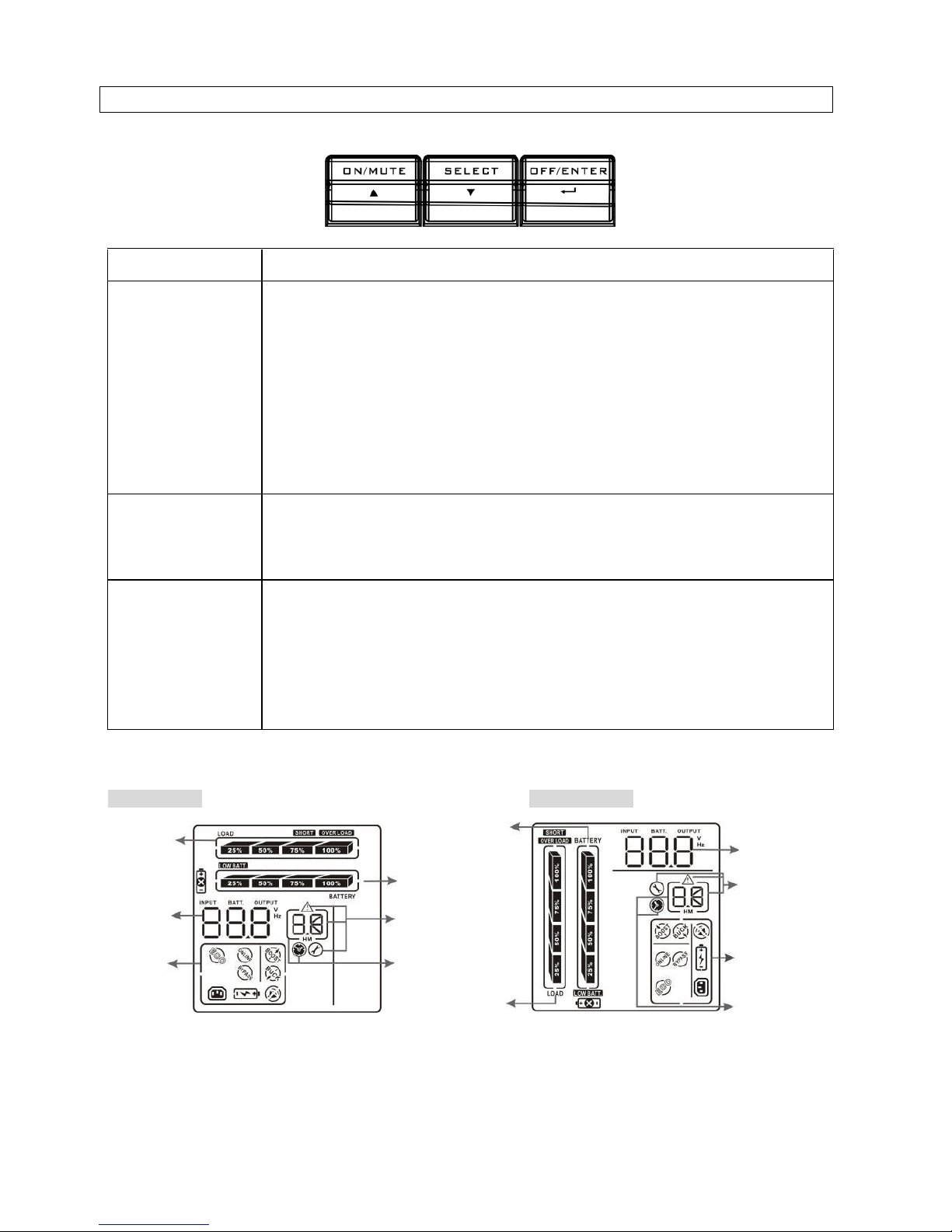
3-1. Button Operation
Button Function
ON/MUTE Button
Turn on the UPS: Press and hold ON/Mute button for at least 2
seconds to turn on the UPS.
Mute the alarm: After the UPS is turned on in battery mode, press
and hold this button for at least 5 seconds to disable or enable the
alarm system. But it’s not applied to the situations when warnings or
errors occur.
Down key: Press this button to display previous selection in UPS
setting mode.
Switch to UPS self-test mode: Press ON/Mute buttons simultaneously
for 5 seconds to enter UPS self-testing while in AC mode
OFF/ENTER
Button
Turn off the UPS: Press and hold this button at least 2 seconds to turn
off the UPS
Confirm selection key: Press this button to confirm selection in UPS
setting mode.
SELECT Button
Switch LCD message: Press this button to change the LCD message
for input voltage, input frequency, battery voltage, output voltage
and output frequency.
Setting mode: Press and hold this button for 5 seconds to enter UPS
setting mode when UPS is off.
Up key: Press this button to display next selection in UPS setting
mode.
3-2. LCD Panel
Rack Display Tower Display
Battery info
Load info
Input/output
and Battery
info
UPS status
Warning
& Fault info/
Setting
operation
Backup
time
info
Load info
UPS status
Backup time
info
Input/output
and Battery
info
Warning & Fault info/
Setting operation
Battery info
Page 10
9
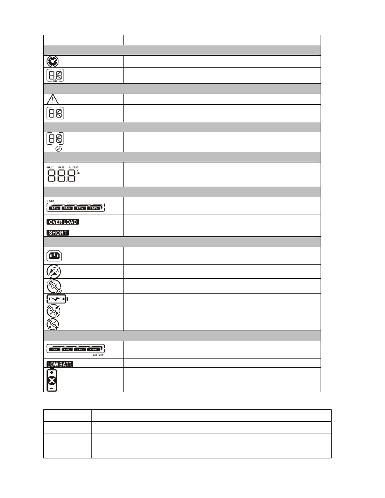
Display Function
Backup time information
Indicates the backup time in pie chart.
Indicates the backup time in numbers.
H: hours, M: minute
Warning & Fault information
Indicates that the warning and fault occurs.
Indicates the warning and fault codes, and the codes are
listed in details in 3-5 section.
Setting Operation
Indicates the setting operation.
Input/Output & Battery information
Indicates the output/input voltage, output/input frequency or
battery voltage.
V: voltage, Hz: frequency
Load information
Indicates the load level by 0-25%, 26-50%, 51-75%, and
76-100%.
Indicates overload.
Indicates the load or the UPS output is short circuited.
UPS status
Indicates that programmable management outlets are
working.
Indicates that the UPS alarm is disabled.
Indicates the UPS powers the output directly from the mains
Indicates the battery charger is working.
Indicates the UPS is working in boost mode
Indicates the UPS is working in buck mode
Battery information
Indicates the Battery level by 0-25%, 26-50%, 51-75%, and
76-100%.
Indicates low battery.
Indicates there is something wrong with battery.
3-3. Audible Alarm
Battery Mode Sounding every 4 seconds
Low Battery Sounding every second
Overload Sounding twice every second
Fault Continuously sounding
Page 11
10
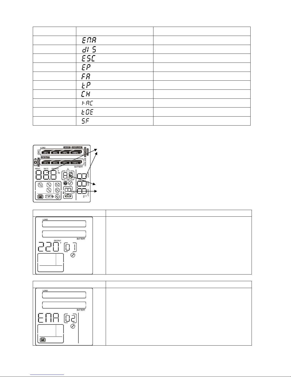
3-4. LCD Display Wordings Index
Abbreviation Display content Meaning
ENA Enable
DIS Disable
ESC Escape
EP EPO
FA Fan
TP Temperature
CH Charger
RAC Rack display
TOE Tower display
SF Site Fault
3-5. UPS Setting
There are two parameters to set up the
UPS.
Parameter 1: It’s for program
alternatives. There are 4 programs to
set up: output voltage setting, ,
programmable outlets enable/disable,
programmable outlets setting ,
LCD display direction and exit.
01: Output voltage setting
Interface Setting
For 208/220/230/240 VAC models, you may choose the
following output voltage:
208: presents output voltage is 208Vac
220: presents output voltage is 220Vac
230: presents output voltage is 230Vac
240: presents output voltage is 240Vac
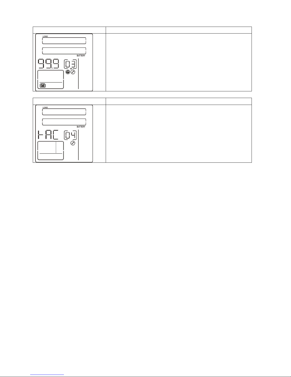
02: Programmable outlets enable/disable
Interface Setting
ENA: Programmable outlets enable
DIS: Programmable outlets disable
Parameters 1
Parameters 2
Page 12
11
03: Programmable outlets setting
Interface Setting
Setting the backup time limits in minutes from 0-999 for
programmable outlets which connect to non-critical devices
on battery mode.
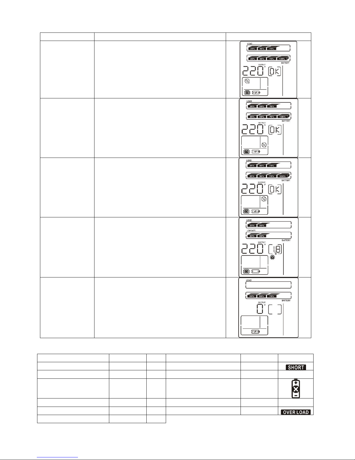
04: LCD display direction setting
Interface Setting
RAC: the LCD display is horizontal.
TOE: the LCD display is vertical.
00: Exit setting
Page 13
12
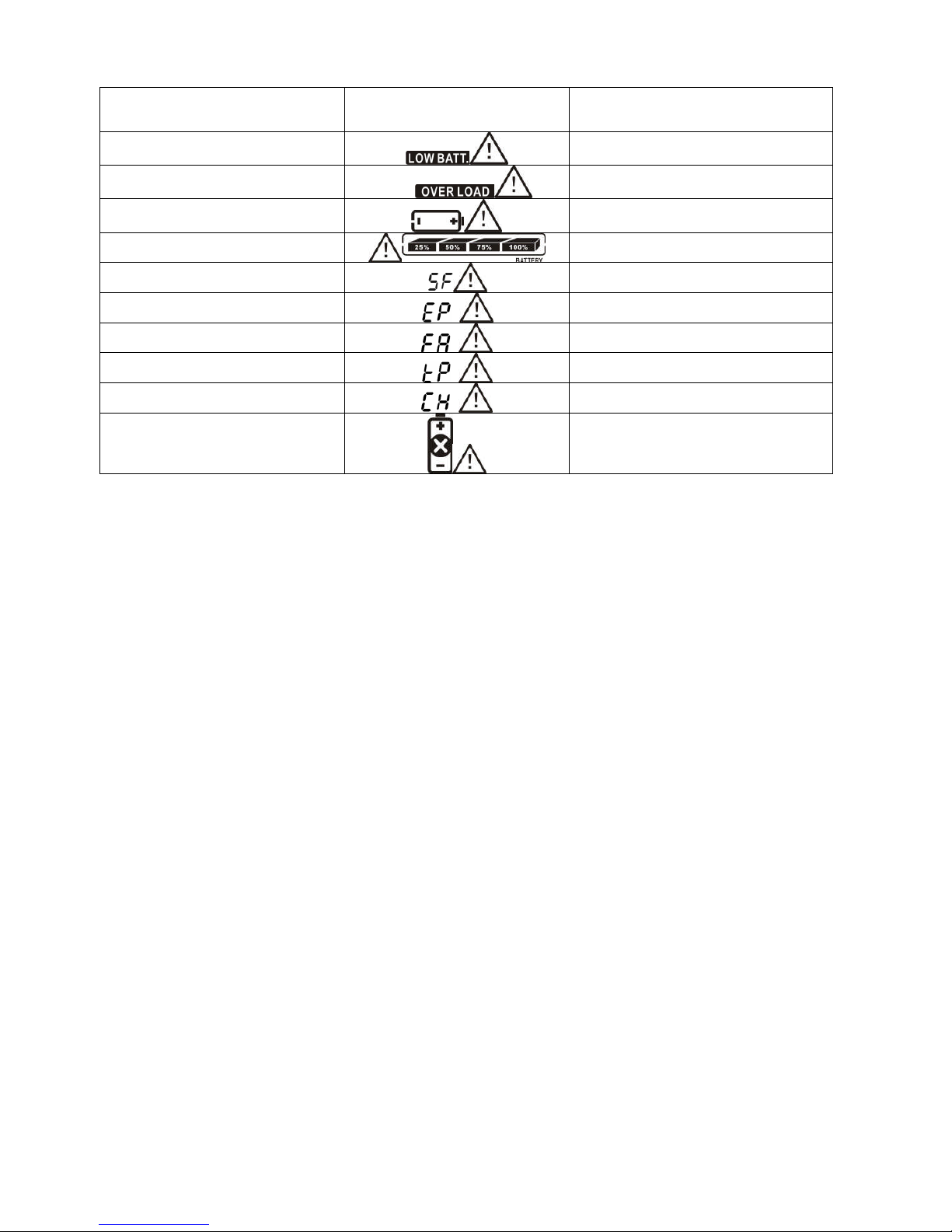
3-6. Operating Mode Description
Operating mode Description LCD display
ECO mode When the input voltage is within voltage
regulated range, UPS will power the output
directly from the mains.
Buck mode
when AC is
normal.
When the input voltage is higher than the
voltage regulation range but lower than
high loss point, the buck AVR will be
activated.
Boost mode
when AC is
normal.
When the input voltage is lower than the
voltage regulation range but higher than
low loss point, the boost AVR will be
activated.
Battery mode When the input voltage is beyond the
acceptable range or power failure and
alarm is sounding every 4 seconds, UPS will
backup power from battery.
Standby mode UPS is powered off and no output supply
power, but still can charge batteries.
3-7. Faults Reference Code
Fault event Fault code Icon Fault event Fault code Icon
Bus start fail 01 x Inverter output short 14
Bus over 02 x Battery voltage too high 27 x
Bus under 03 x Battery voltage too low 28
Inverter soft start fail 11 x Over temperature 41 x
Inverter voltage high 12 x Over load 43
Inverter voltage Low 13 x
Page 14
13
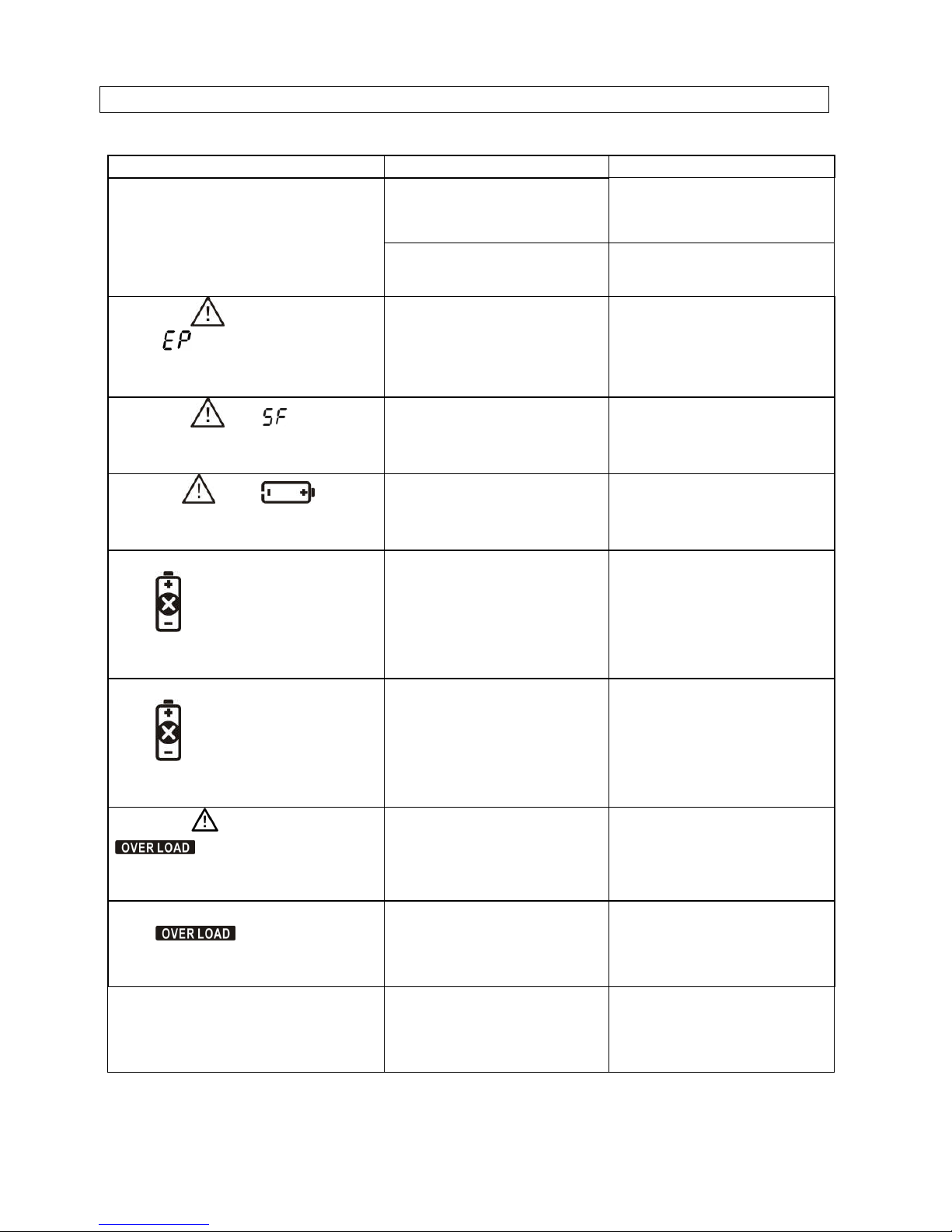
3-8. Warning Indicator
Warning Icon (flashing) Alarm
Low Battery Sounding every second
Overload Sounding twice every second
Battery is not connected Sounding every second
Overcharge Sounding every second
Site wiring fault Sounding every second
EPO enable Sounding every second
Fan Failure Sounding every second
Over temperature Sounding every second
Charger failure Sounding every second
Battery Fault Sounding every second
Page 15
14
4. Troubleshooting
If the UPS system does not operate correctly, please solve the problem by using the table
below.
Symptom Possible cause Remedy
The AC input power is not
connected well.
Check if input power cord
firmly connected to the
mains.
No indication and alarm even
though the mains is normal.
The AC input is connected
to the UPS output.
Plug AC input power cord
to AC input correctly.
The icon and the warning
code flashing on LCD
display and alarm is sounding
every second.
EPO function is activated. Set the circuit in close
position to disable EPO
function.
The icon and flashing
on LCD display and alarm is
sounding every second.
Line and neutral
conductors of UPS input
are reversed.
Rotate mains power socket
by 180° and then connect
to UPS system.
The icon and flashing
on LCD display and alarm is
sounding every second.
The external or internal
battery is incorrectly
connected.
Check if all batteries are
connected well.
Fault code is shown as 27 and the
icon is lighting on LCD
display and alarm is continuously
sounding.
Battery voltage is too high
or the charger is fault.
Contact your dealer.
Fault code is shown as 28 and the
icon is lighting on LCD
display and alarm is continuously
sounding.
Battery voltage is too low
or the charger is fault.
Contact your dealer.
The icon and the icon
are flashing on LCD
display and alarm is sounding
twice every second.
UPS is overload Remove excess loads from
UPS output.
Fault code is shown as 43 and The
icon is lighting on LCD
display and alarm is continuously
sounding.
The UPS shut down
automatically because of
overload at the UPS
output.
Remove excess loads from
UPS output and restart it.
Fault code is shown as 14 and
alarm is continuously sounding.
The UPS shut down
automatically because
short circuit occurs on the
UPS output.
Check output wiring and if
connected devices are in
short circuit status.
Page 16

15
Symptom Possible cause Remedy
Fault code is shown as 1, 2, 3, 4,
11, 12, 13 and 41 on LCD display
and alarm is continuously
sounding.
A UPS internal fault has
occurred.
Contact your dealer
Batteries are not fully
charged
Charge the batteries for at
least 5 hours and then
check capacity. If the
problem still persists,
consult your dealer.
Battery backup time is shorter
than nominal value
Batteries defect Contact your dealer to
replace the battery.
The icon and the warning
code flashing on LCD display
and alarm is sounding every
second.
Fan is locked or not
working
Check fans and notify
dealer!!
Page 17
16
5. Storage and Maintenance
5-1. Operation
The UPS system contains no user-serviceable parts. If the battery service life (3~5 years
at 25°C ambient temperature) has been exceeded, the batteries must be replaced. In this
case, please contact your dealer.
Storage
Before storing, charge the UPS 5 hours. Store the UPS covered and upright in a cool, dry
location. During storage, recharge the battery in accordance with the following table:
Storage Temperature Recharge Frequency Charging Duration
-25°C - 40°C Every 3 months 1-2 hours
40°C - 45°C Every 2 months 1-2 hours
Be sure to deliver the spent battery to a recycling facility or ship it to your
dealer in the replacement battery packing material.
Page 18

17
MODEL Otima 800 Otima 1.1K Otima 1.5K Otima 2K Otima 2.5K Otima 3K
CAPACITY
800 VA /
640 W
1100 VA /
880 W
1500 VA /
1200 W
2000 VA /
1600 W
2500 VA /
2000 W
3000 VA /
2400 W
INPUT
Acceptable Voltage Range 81-145 VAC or 162-290 VAC
Frequency Range 60/50 Hz (auto sensing)
OUTPUT
Voltage Regulation (AC
Mode)
110/120 VAC or 208/220/230/240 VAC
Voltage Regulation (Batt.
Mode)
±3%(before battery alarm)
Frequency Range (Batt.
Mode)
50 Hz or 60 Hz ± 1 Hz
Current Crest Ratio 3:1
Harmonic Distortion 8% max @ 100% linear load, 15% max @ 100% non-linear load (before alarm)
Transfer Time Typical 2-6 ms, 10ms max.
Waveform (Batt. Mode) Pure Sine Wave
EFFICIENCY
AC Mode 98% 98% 98%
Buck & Boost Mode 90% 90% 90%
Battery Mode 83% 85% 87%
BATTERY
Battery Type & Number 12 V/7 Ah x 2 12 V/9 Ah x 2 12 V/7 Ah x4 12 V/9 Ah x4 12 V/7 Ah x6 12V/9Ahx6
Charging Voltage 27.4 VDC ± 1% 54.8 VDC ± 1% 82.1 VDC ± 1%
Typical Recharge Time 4 hours recover to 90% capacity
PROTECTION
Full Protection Overload, short, discharge, and overcharge protection
ALARM
Battery Mode Sounding every 10 seconds
Low Battery Sounding every second
Overload Sounding every 0.5 second
Battery Replacement Alarm Sounding every second
Fault Continuously sounding
PHYSICAL
Dimension,
DXWXH
(mm)
350 x 438 x 88 480 x 438 x 88 600 x 438 x 88
Standard
Model
Net Weight
(kg)
14.8 15.8 23 25 32 35
ENVIRONMENT
Operating Humidity 0-90 % RH @ 0- 40°C (non-condensing)
Noise Level Less than 45dB
MANAGEMENT
Smart RS-232/USB Supports Windows® 98/2000/2003/XP/Vista/2008,Windows® 7, Linux, and MAC
Optional SNMP Power management from SNMP manager and webbrowser
* Derate capacity to 80% of capacity when the output voltage is adjusted to 208VAC.
**Product specifications are subject to change without further notice.
6. Specifications
 Loading...