

Page 1
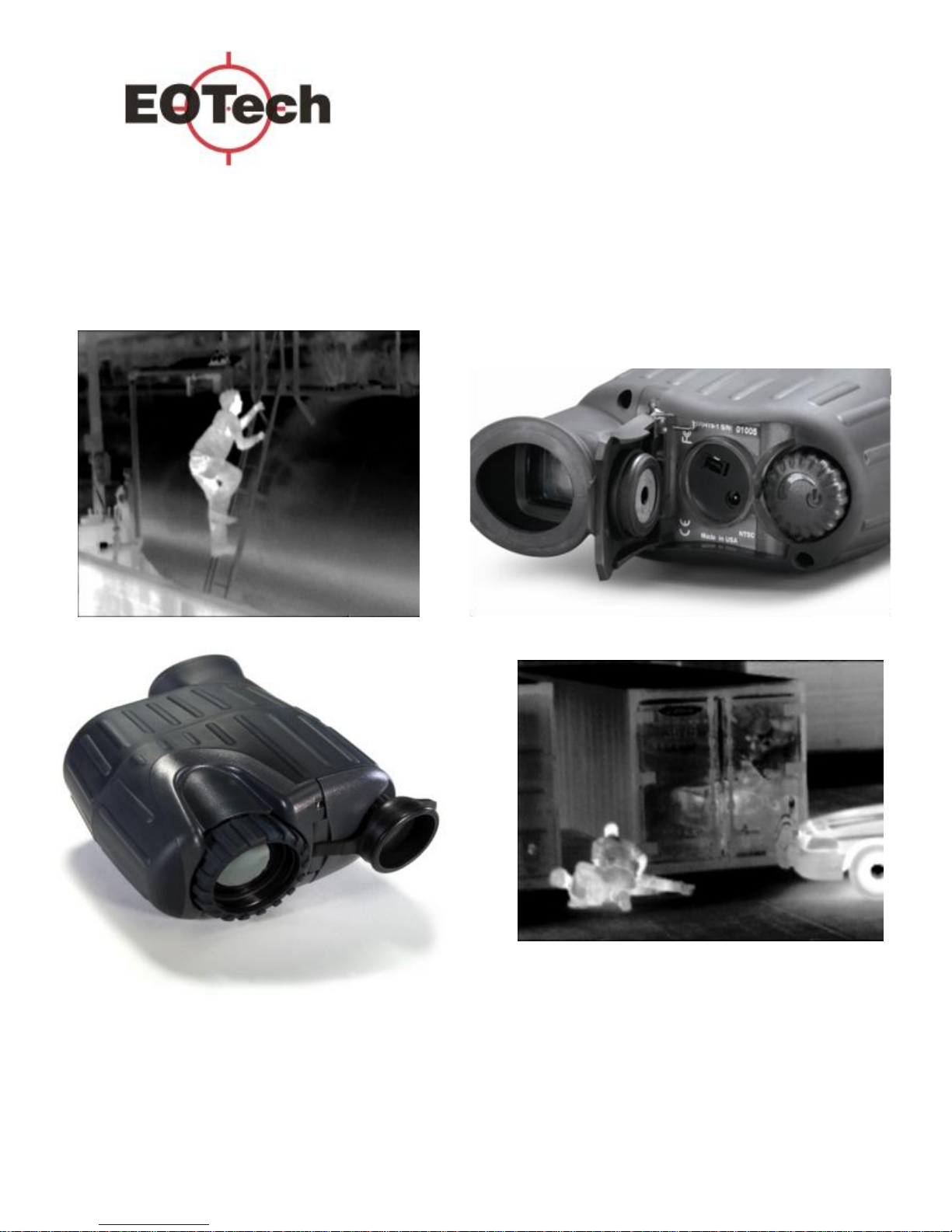
See the Unseen
User Manual
X320 and X640 Thermal Imager
Page 2

2
This equipment has been tested and found to comply with the limits for a
Class B digital device, pursuant to Part 15 of the FCC rules. These limits are
designed to provide reasonable protection against harmful interference in a
residential installation. This equipment generates, uses, and can radiate radio
frequency energy and, if not installed and used in accordance with the
instructions, may cause harmful interference to radio communications.
However, there is no guarantee that interference will not occur in a particular
installation. If this equipment does cause harmful interference to radio or
television reception, which can be determined by turning the equipment on
and off, the user is encouraged to try to correct the interference by one or
more of the following measures:
─ Reorient or relocate the receiving antenna.
─ Increase separation between equipment and receiver.
─ Connect the equipment into an outlet on a circuit different from that to
which the receiver is connected.
─ Consult the dealer or an experienced radio/TV technician for help.
─ Changes or modifications not expressly approved by L-3
EOTech could void the user’s authority to operate this
equipment.
─ For continued FCC Compliance, use only accessories approved
by L-3 EOTech.
Page 3

3
User Manual P/N 5002035-1 Rev J
©2015 L-3 EOTech. All Rights Reserved
Patents
This product is covered by one or more of the following patents: U.S. Patent Nos.:
5,288,649; 5,367,167; 6,267,501; 6,586,831; 6,521,477; 6,690,014; 6,479,320,
6,879,035, 7,015,074, 7,262,412, 7,375,331, 7,718,965, 7,655,909, 6,777,681,
8,183,513, and under license to 5,196,703. Euro.Pat.Application. 1159591.
Additional Patents Pending.
Export
EXPORT CONTROL NOTICE – This technical data and software is considered as
Technology Software Publicly Available (TSPA) No License Required (NLR) as defined
in Export Administration Regulations (EAR) Part 734.7-11.
Registered Trademarks of L-3 EOTech
Page 4

4
X320 CE Manufacturers Declaration of Conformity:
Tested By
NTS
1701 E Plano Pkwy, Ste 150
Plano, TX. 75074
Manufacturer
L-3 EOTech
3414 Herrmann Dr
Garland, TX 75041
Product Identification:
Product: Thermal Infrared Camera
Model/Type: X320 Camera
Version: 5002020-1 and -2 and 5002021-1 and -2
EU Representative
Acal BFi France SAS
4 Allée du Cantal, ZI La Petite Montagne Sud
CE1834 Lisses – 91018, EVRY Cedex, France Tel: +33 (0) 1 60 79 59 55
A Sample of this product has been tested:
To demonstrate compliance with: EN61000-6-1 & EN61000-6-3
Using the following test standards: EN61000-4-2, EN61000-4-3,
EN61000-4-4, EN61000-4-5, EN61000-4-6, EN61000-4-11
Means of conformity
The product is in conformance with the above standards according to 89/336/EEC
Page 5

5
X640 CE Manufacturers Declaration of Conformity:
Tested By
NTS
1701 E Plano Pkwy, Ste 150
Plano, TX. 75074
Manufacturer
L-3 EOTech
3414 Herrmann Dr
Garland, TX 75041
Product Identification:
Product: Thermal Infrared Camera
Model/Type: X640 Camera
Version: 5002330-1 and -2 and 5002331-1
EU Representative
Acal BFi France SAS
4 Allée du Cantal, ZI La Petite Montagne Sud
CE1834 Lisses – 91018, EVRY Cedex, France Tel: +33 (0) 1 60 79 59 55
A Sample of this product has been tested:
To demonstrate compliance with: EN61000-6-1 & EN61000-6-3
Using the following test standards: EN61000-3-2, EN61000-3-3, EN61000-4-2,
EN61000-4-3, EN61000-4-4, EN61000-4-5, EN61000-4-6, EN61000-4-8,
EN61000-4-11
Means of conformity
The product is in conformance with the above standards according to 89/336/EEC
Page 6

6
1. Introduction ............................................................................... 7
Welcome to Infrared .......................................................... 7
Handling & Precautions.......................................................9
Contacting L-3 Communications Infrared Products ........... 9
2. Operation................................................................................. 10
The Thermal Imaging Camera ......................................... 10
Holding the Camera ......................................................... 11
Loading the Batteries ....................................................... 12
Turning on the Power....................................................... 13
─ Rotate the User Control Switch............................... 13
─ Camera Warm-Up ................................................... 14
─ Camera Shutter ....................................................... 14
─ Automatic Contrast ................................................. 14
─ Checking the Battery Power ................................... 14
Adjusting the Display Brightness..................................... 16
Activating User Defined Functions .................................. 16
Focusing for Close-up Operation ..................................... 17
Cleaning ........................................................................... 18
3. GUI ........................................................................................... 19
Multi-function Button Settings ........................................ 21
4. Accessories ............................................................................. 27
Accessory Video & Power Adapter ................................ . 27
Operating With Video & External Power ........................ 28
Specifications ................................................................... 29
Frequently Asked Questions ............................................ 32
Trouble Shooting Guide ................................................... 33
Warranty .......................................................................... 34
Page 7

7
1. Introduction
Thank you for choosing the X320 or X640 Thermal Imaging
Camera. With its small size, rugged design, and simplicity, you can
now focus on the job at hand, rather than the camera in your hand.
Before using this camera, please read these instructions carefully,
and retain them for future reference.
Welcome to Infrared
L-3 EOTech has long been a leader in the production and
development of military products based on infrared thermal imaging.
In an effort to make this technology more widely available, L-3
EOTech's engineers and scientists developed many unique ways of
translating infrared energy into visible imagery. Now L-3 EOTech is
providing affordable thermal imaging solutions for fire, law
enforcement, marine, security, and other commercial uses.
Infrared energy often referred to as “infrared” or “IR”, is
electromagnetic radiation that travels in a straight line through space,
similar to visible light. Although infrared shares some of the
properties of visible light, its different wavelength has several unique
characteristics. For instance, materials that are opaque to visible light
may be transparent to infrared, and vice–versa. Also, unlike visible
light, which is given off by ordinary objects only at very high
temperatures (e.g. light bulbs), long wavelength infrared (7–14 m)
is emitted by all objects at ordinary temperatures. This means
infrared is all around us all the time, even in the dark. Different
objects give off varying amounts of infrared, depending on the
temperature of the object.
Page 8
8
The thermal imaging camera was designed to sense differing
amounts of long wavelength infrared coming from the various areas
of a scene and to convert them to corresponding intensities of visible
light on a display. This allows true see–in–the–dark capability, as
well as the ability to discern additional information—differences in
temperature—by observing the thermal properties of objects in any
light condition.
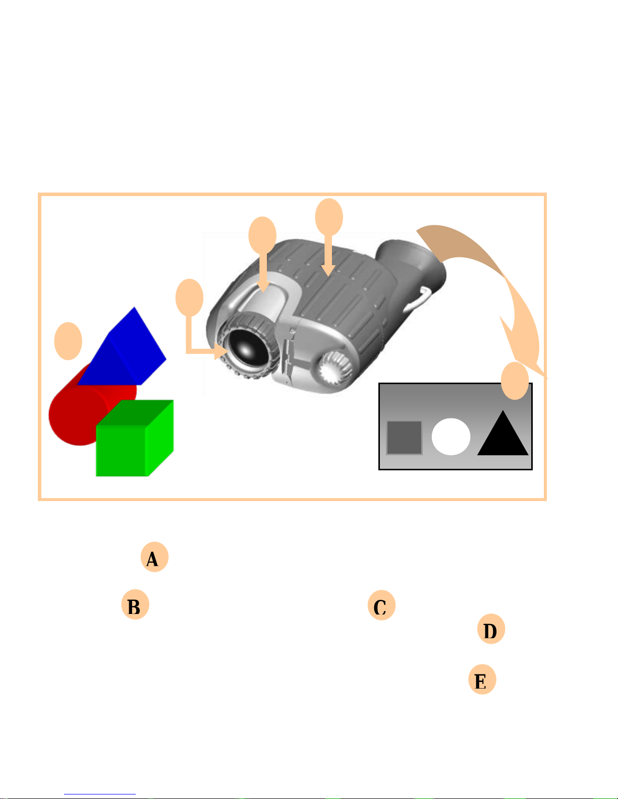
Infrared energy is emitted proportionally to the temperature
of an object . The warmer the object, the more energy it
emits. The infrared energy from the objects is focused by
the optics , onto an infrared detector . The information
from the Infrared detector is passed to electronics for
image processing. The signal processing circuitry translates
the infrared detector data into an image that can be viewed
on the built-in video monitor.
HOT
COLD
WARM
A
B
C
D
E
Page 9

9
Handling and Precautions
All batteries can cause property damage or bodily injury if a
conductive material such as jewelry or keys touch exposed
terminals. Exercise care when placing batteries inside a pocket,
case, or other container with metal objects.
Do not replace batteries in a potentially explosive atmosphere,
such as a gas station or any place where you might normally be
advised to turn off your vehicle engine. Contact sparking may
occur and cause an explosion.
Do not remove power – removing batteries or disconnecting
optional external power supply – without first turning the
camera off using the on/off switch.
Do not permanently attach this camera to dynamic–mount
applications, such as on vehicles or heavy machinery, in which
transmitted vibration is continuously sustained.
Never point this camera directly into the sun, welding arcs,
or any other extreme intensity objects that you would not
view with your eyes. Doing so will damage the Camera.
Contacting L-3 EOTech
The Customer Service Department is available to assist with questions about
this product. If returning for repair, see Page 34 for instructions. When
you contact us, please have the following information available:
-Camera Part Number -Camera Serial Number
[Serial Number is located under the rear door/plug.]
L-3 EOTech Customer Service Department: 1-888EOTHOLO
Page 10
10
2. Operation
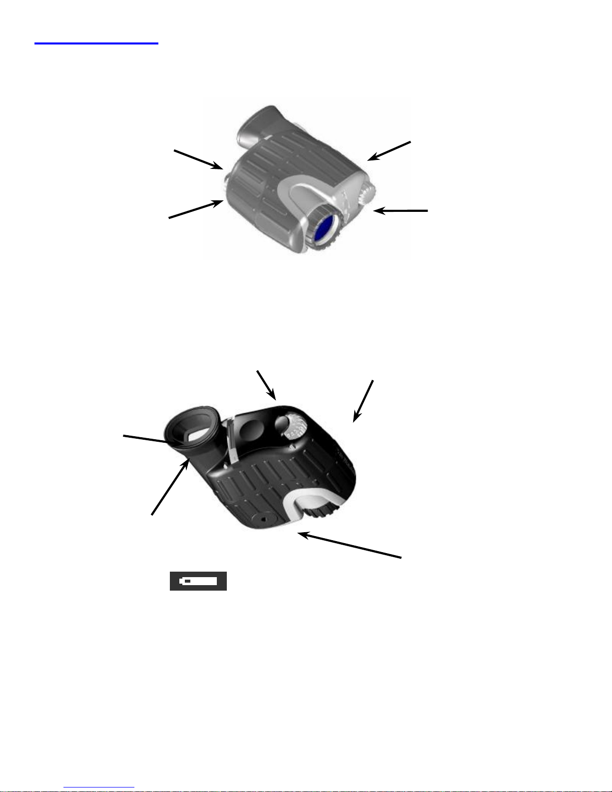
The X320 or X640 Thermal Imaging Camera
Rubber Armored
construction
Submersible to 1 meter
Floats in water
Standard AA
Lithium
Batteries
User Control Switch:
Rotate for On/Off and
display brightness
Short push for
electronic zoom
Long push for
White/Black Hot, Hot
Target Level I/II, and
Custom Color
Variable
Brightness
Display
Connect External Power,
USB, or external Video.
(Power requires optional power
adapter)
Serial Number is behind the external connections plug
Tripod Mount
(1/4-20 thread)
Battery Icon – indicates
battery level
Page 11
11
Holding the Camera
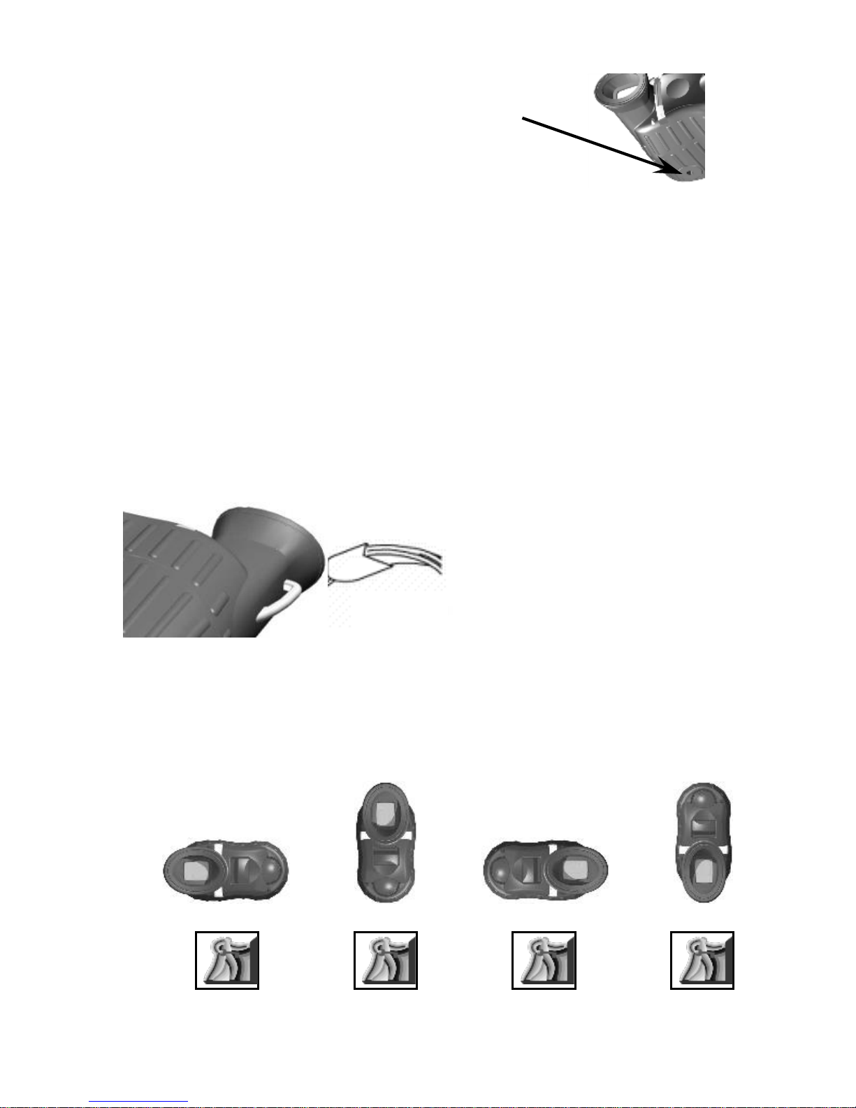
The Camera can be mounted
to a tripod using the 1/4-20 insert.
The Camera can be held either right-handed, or left-handed.
To avoid dropping the camera,
attach the strap provided. Both a neck
strap and a wrist strap are provided for
your convenience. Attach the strap to
the camera by looping it through the
attachment point as shown here.
The camera can be held in any orientation – and the image in
the LCD Display remains upright (except symbology).
Page 12
12
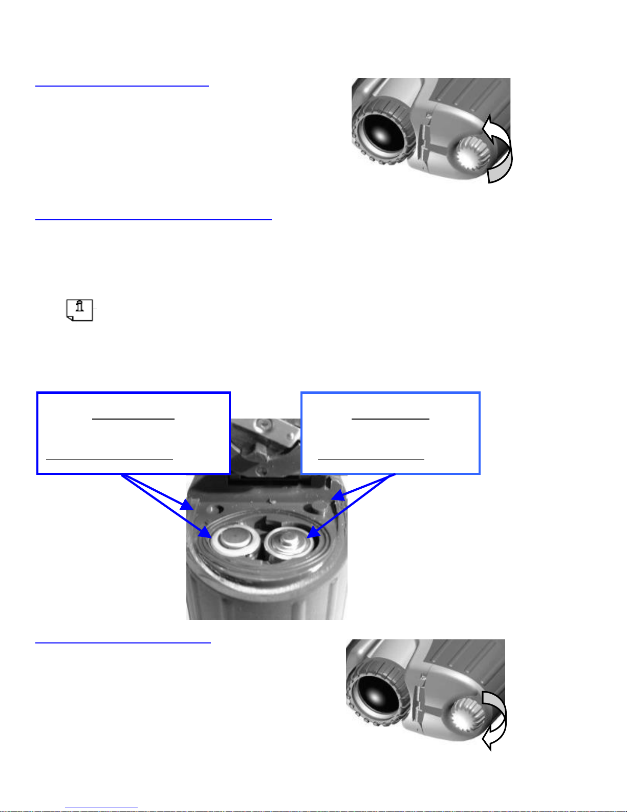
Loading the Batteries
Open the battery Door
Unscrew Battery Door knob
Counterclockwise
Open the door to install batteries
Install 2 AA Lithium Batteries
“+” & “ – “ symbols inside the battery compartment indicate the
direction to install batteries
Notice the Raised Tab next to the (+) sign, and the Sunken
Tab next to the (-) sign. These tabs allow the user to
install the batteries in complete darkness by “feel” without having to “see” the battery symbols.
Close the battery Door
Close the Battery Door
Screw Battery Door Knob
Clockwise
Sunken Tab
Insert battery with
Positive end down.
Raised Tab
Insert battery with
Positive end up.
Page 13
13
Batteries
L-3 EOTech recommends the use of Lithium AA batteries. The
camera can operate with Alkaline, Nickel-Metal-Hydride
(NiMh) rechargeable, but performance and battery life may be
inconsistent.
*L91 Lithium batteries are recommended for maximum
operating time.
The camera does not have an internal battery charger. If using
rechargeable batteries, they must be charged with a separate
external charger.
Replacing Batteries
Before removing/replacing batteries, always ensure the camera
is first turned off.
Batteries
When replacing batteries, always replace BOTH batteries.
Mixing a fresh battery with a partially discharged battery is
potentially hazardous.
Never mix battery types (Alkaline, rechargeable, Lithium, etc).
Both batteries must be of the same type.
Remove batteries if the camera is to be stored for extended
periods (2 weeks or more).
Always follow the battery manufacturers’ directions for proper
disposal of batteries.
Turning on the Power
Rotate the User Control Switch
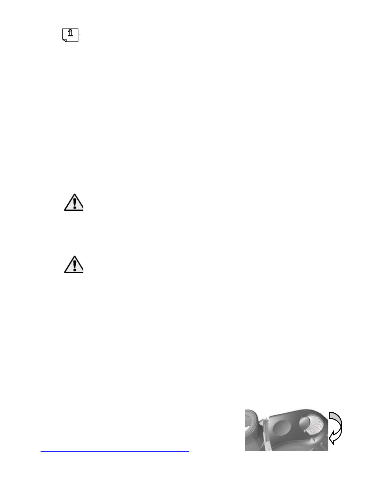
Rotate the user control switch clockwise to turn on the camera.
Page 14

14
Camera Start-Up
The camera requires approximately 5 seconds of start-up time.
During these 1st 5 seconds after the camera is switched on, a logo
will appear in the Display. After 5 seconds have passed, the logo
will disappear, and video of the thermal scene begins.
Camera Shutter
To maintain an optimum Thermal Image, the camera automatically
shutters. During this shutter, the video freezes for approximately 3/4
second, and a faint “click” sound may be heard inside the camera.
Shuttering occurs in the 1st 2 minutes after turning on the camera at
30-second intervals. Otherwise, the camera shutters only if its
internal temperature changes by 2°C or more.
Automatic Contrast
Video contrast is constantly adjusted either higher or lower, based
upon the informational content in the scene.
When viewing people, automobiles, boats, and other warm objects
at close range, the video gain is automatically decreased to provide
more detail on facial features and flat surfaces.
When viewing a scene with low informational content, i.e. a park,
field, or roadway, the video gain is automatically increased to
provide more detail in the background of the scene, e.g. trees, bushes,
roadway edges.
Checking the Battery Power
A battery icon appears in the built-in LCD display, to indicate the
approximate amount of charge remaining in the batteries. New
Alkaline Batteries generally provide enough charge for
approximately 2 hours of continuous operation, while new Lithium
Page 15

15
L91 Batteries provide enough charge for approximately 6 hours of
operation.
Operating Time is based on a display set to minimum brightness
(night-time setting), and camera at room temperature.
Very Low or Very High temperatures, and Brightness Setting of the
Display, could reduce the expected time of operation by 50%.
Partially used alkaline batteries may not have enough energy to start
the camera, reducing total operating time.
If the camera is run until the batteries do not have enough power to operate
the camera, it closes the shutter, stops operating and displays a white screen.
A flashing blue screen may also be displayed. At this point, the batteries
should be replaced. If the optional external power adapter is used and the
batteries are depleted, they must be removed for the camera to operate
normally.
The battery icon is most accurate when using Lithium batteries, and slightly
less accurate when using NiMh or Alkaline batteries.
FULL
EMPTY
Page 16
16
Adjusting the Display Brightness
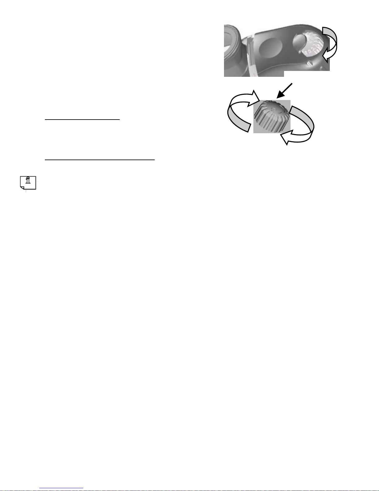
Turn the User Control Switch
past the on/off detent, continuing
to increase the LCD display brightness.
Brighter LCD Display:
Turn Clockwise
Dimmer LCD Display:
Turn Counterclockwise
To maximize battery life, set the LCD Display to the minimum
brightness setting practical.
Activating User Defined Functions
The thermal imaging camera has a set of user defined
functions that are activated by pressing the User Control
Switch and are configurable via the Graphical User Interface
(GUI) using an external computer. Customizing the camera
via the GUI is described in Section 3 of this manual.
There are three User Control Switch push modes: Short
Push, Long Push, and Extended Long Push.
Short Push – Press momentarily and release. The change occurs
when the switch is released. The default function for a short
push is electronic zoom.
Long Push – Press and hold User Control Switch for period
greater than 2/3 of a second and less than 5 seconds. Change
automatically occurs, then release the switch. The default
On
Off
Dim
Bright
Function
Page 17
17
function for a long push is to cycle through white/black hot and
colorized video modes.
Extended Long Push (Factory Defined) – Press and hold User
Control Switch for period longer than 5 seconds. *An
Extended Long Push resets the camera to factory defaults.
This may be desireable if the user wishes to undo any changes
that were made using the GUI and return the camera to original
out of the box configuration.
The user defineable functions are: electronic zoom,
white/black hot mode, manual touchup, Hot Target Level I
and II, custom color. Definitions of these functions are
defined in Section 3 of this manual.
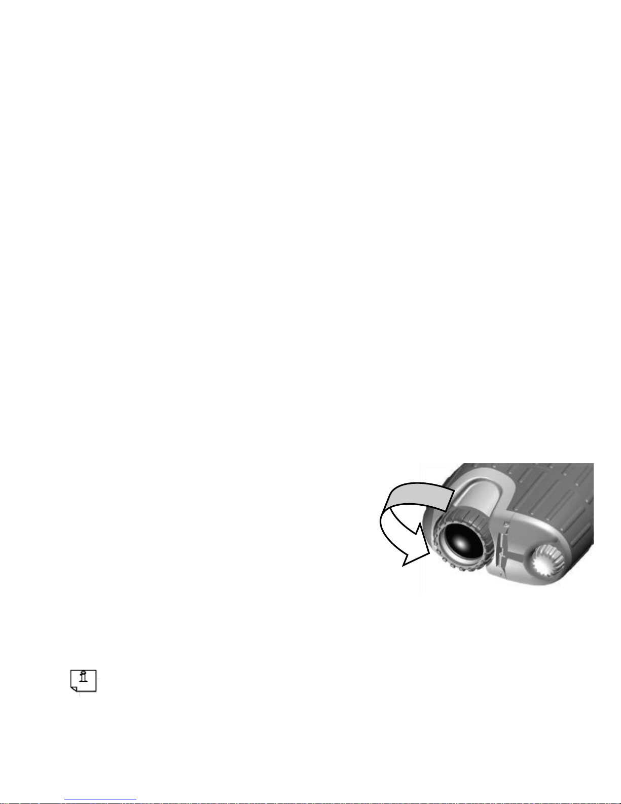
Focusing for Close-up Operation
The X320 or X640 has
overall viewing range from
15ft to infinity. In the Far
Focus position, objects from
15ft to infinity will be in
focus. By rotating the Lens,
objects as close as 4ft can be
brought into focus.
The Lens may feel difficult to turn. This is normal, and is due to the
tight seal required to make the camera waterproof.
FAR
Focus
NEAR
Focus
Page 18

18
Cleaning
Do not apply any chemicals to the camera.
Clean the body of the camera using a water-moistened cloth.
Clean the Lens with a cleaner/cloth that has been specially
formulated for cleaning camera lenses – one is provided, and if
additional cloths are needed, they may be purchased from any
camera retailer.
3. GUI
Included with the X320 or X640 is a Graphical User Interface
(GUI) that the user can use to customize the scene display and
the functionality of the User Control Switch.
Computer Requirements for GUI
Processor/Computer: Pentium 1GHZ (or higher).
RAM: 1GB (or greater)
Hard disk space: 1GB (or greater)
Operating Software:
- Windows XP 32bit
- Windows vista
- Windows 7
- Windows 8
Page 19
19
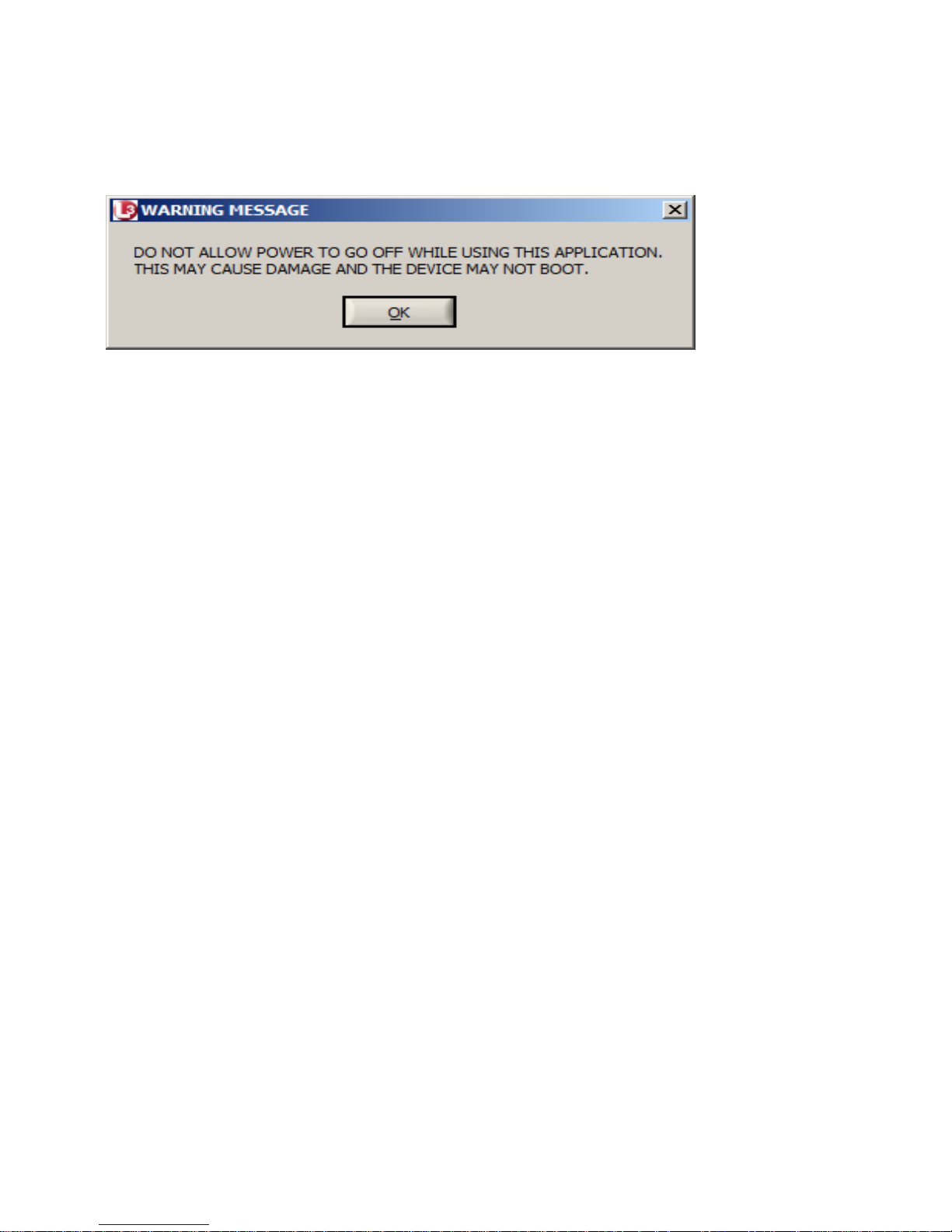
When starting the GUI a warning message appears on the
computer screen
It is recommended that the user insert a fresh set of batteries
or plug the camera into the optional power adapter and
remove the internal batteries when communicating with the
GUI to avoid data loss.
IF THE THERMAL IMAGING CAMERA LOSES
POWER DURING COMMUNICATION WITH THE
GUI, INTERNAL MEMORY OF THE CORE MAY BE
CORRUPTED AND THE CAMERA MAY NOT
FUNCTION PROPERLY UNTIL FACTORY
DEFAULTS ARE RESTORED.
Click OK on the warning message and the GUI panel
appears.
Page 20
20
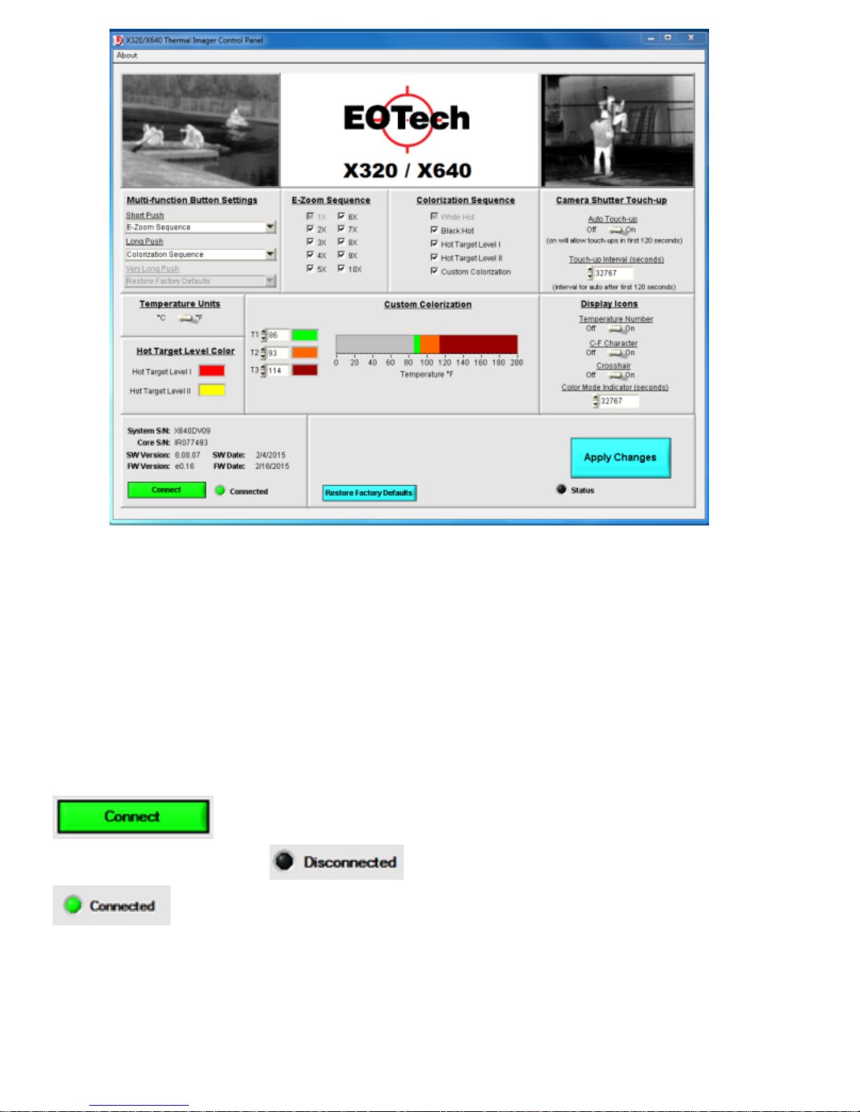
The single panel screen shown above provides access to all
of the customization options available to the user via 10
separate user zones.
First make sure that the camera is turned ON. Next, connect
the camera to a computer USB port using the included cable
with the USB connector. Next, click the Connect button
. Once connected the Status light turns green
and changes from to
and the user can now configure the camera.
Page 21
21
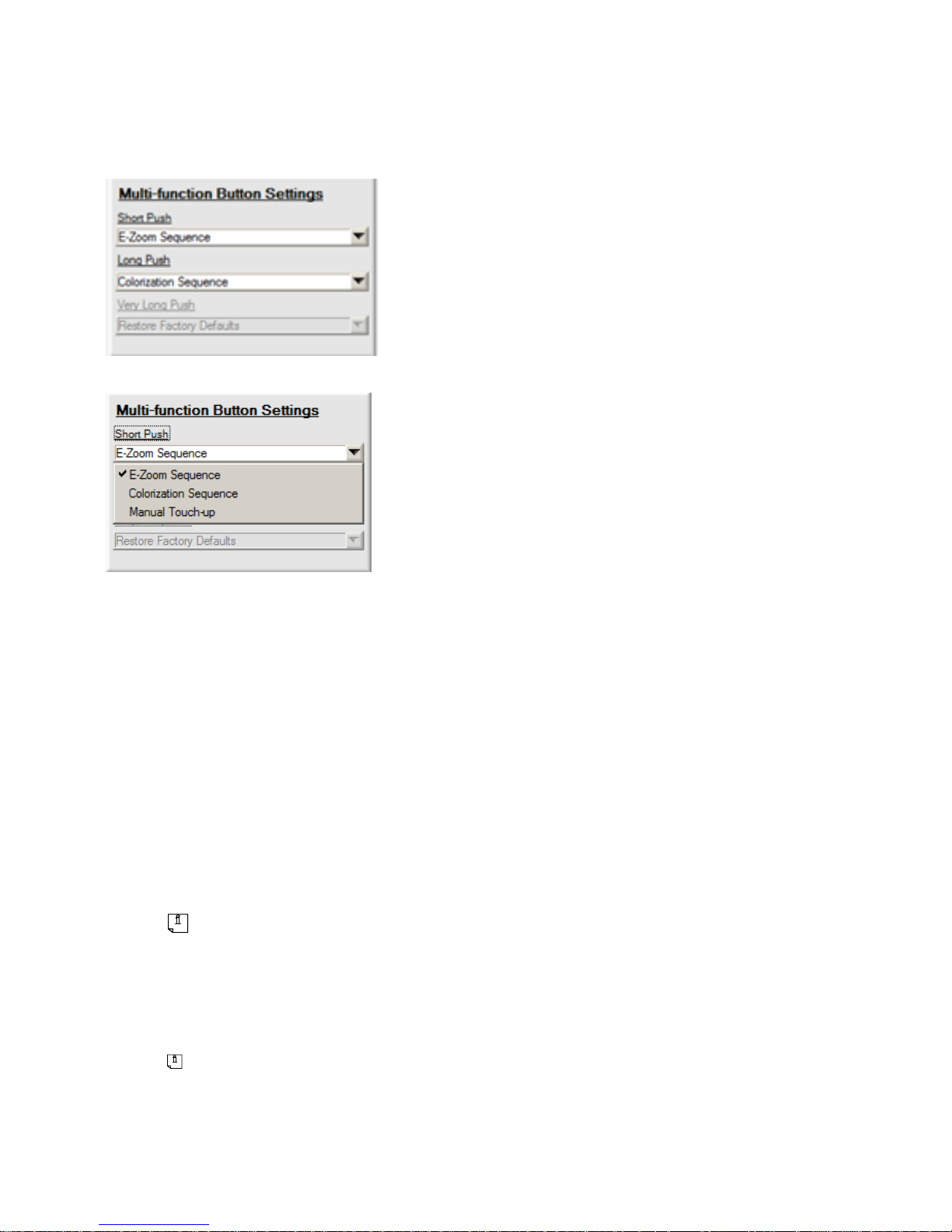
Multi-function Button Settings
This zone configures the operation of the User Control
Switch.
Drop Box Expanded
The Very Long Push drop box is a factory defined function
that resets the camera to factory defaults and is grayed out
since it cannot be re-assigned to another function.
Selecting an option from the drop boxes defines the
operation of the camera when the User Control Switch is
pressed for the specified time period.
The definitions of Short Push, Long Push and Very Long Push
are defined in Section 2 Operation – Activating User Defined
Functions within this manual.
E-Zoom Sequence cycles through the E-Zoom Sequences
defined in the adjacent zone.
Page 22
22
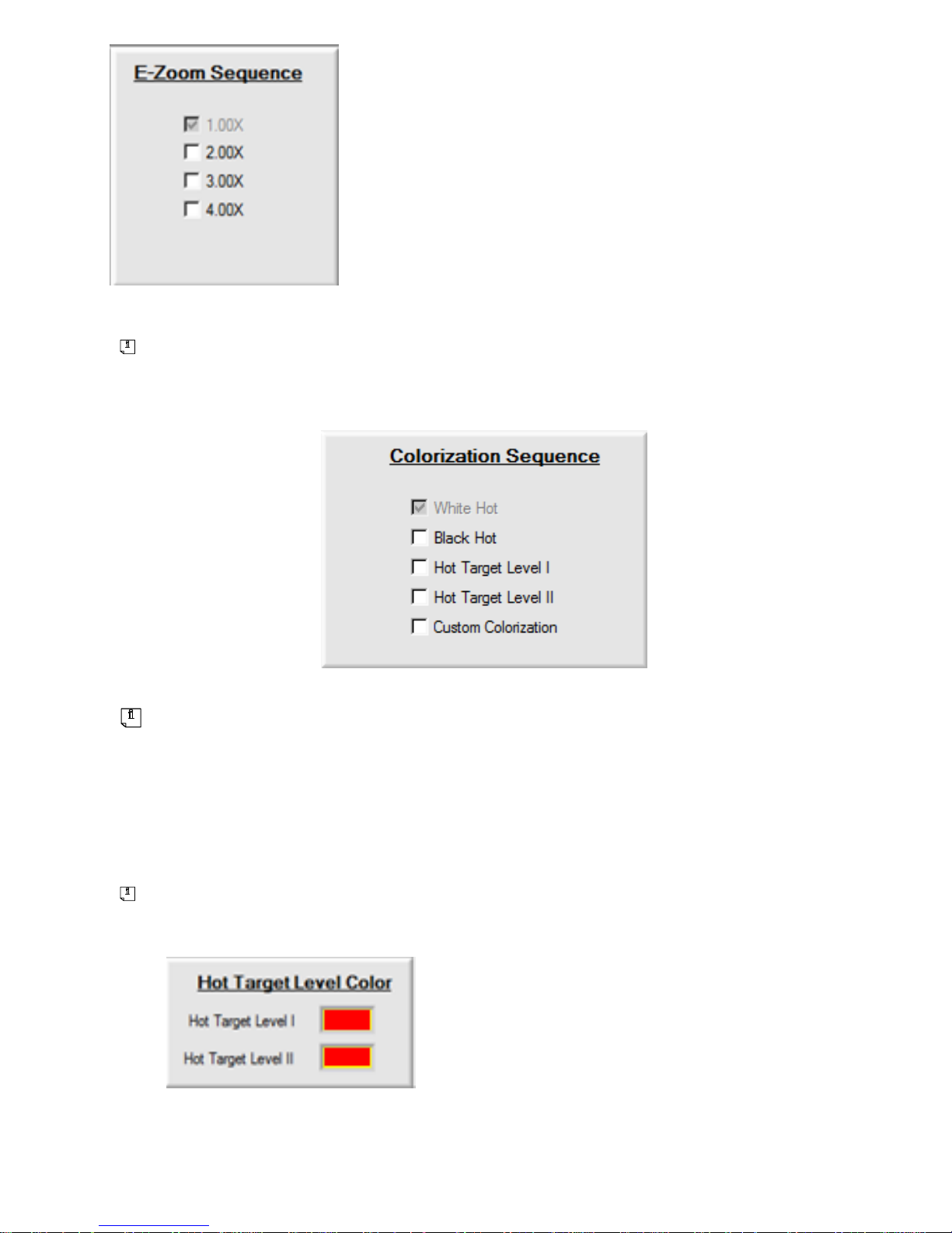
1.00× is always selected and is the default
power up setting. Factory defaults select
1.00× and 2.00× and pressing the User
Control Switch cycles between these two
settings.
Colorization Sequence sets the X320 to toggle through the
selections made in the Colorization Sequence zone
White Hot means that cold objects in the scene appear black and
hot objects appear white with all objects between being shades
of gray. Black Hot reverses the setting so that hot objects
appear black and cool objects appear white.
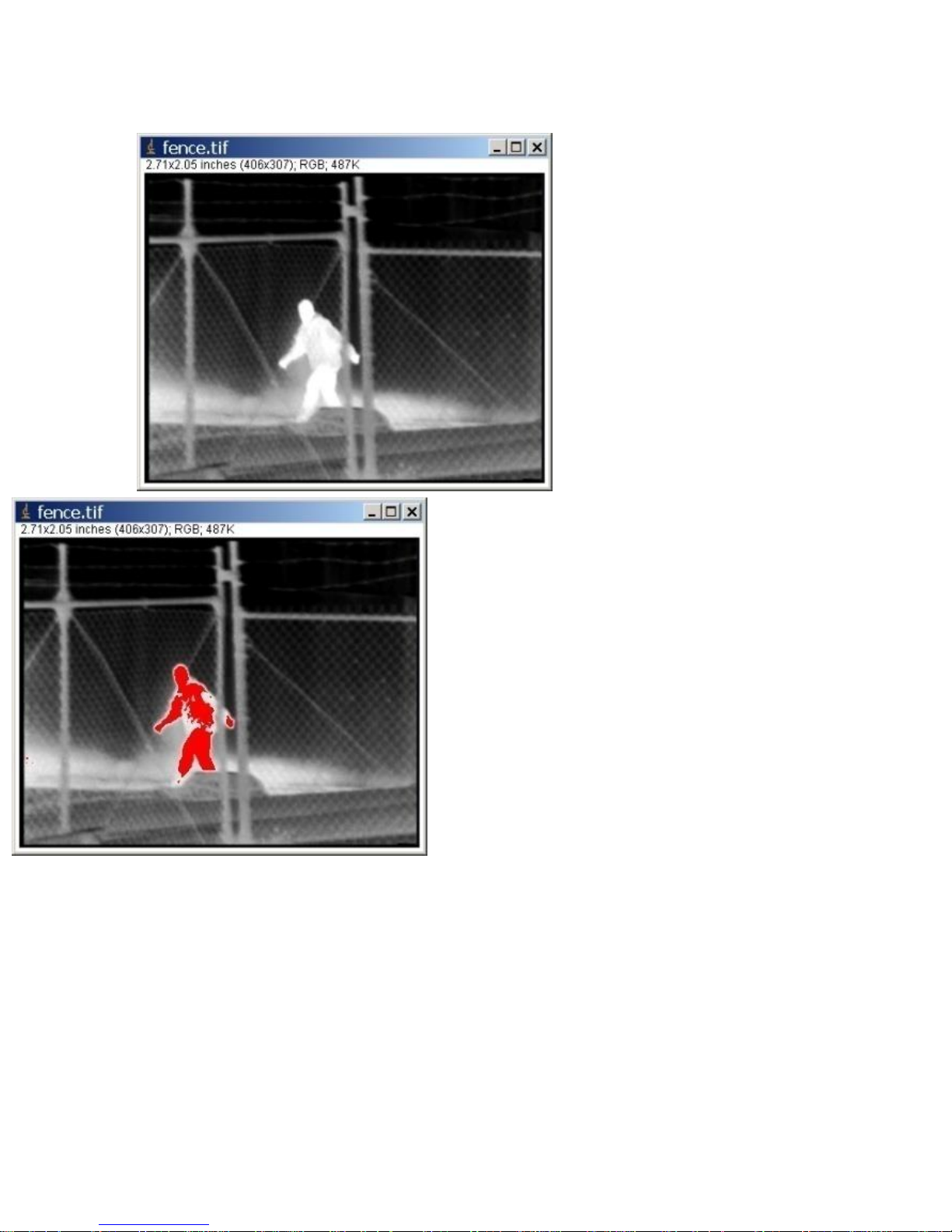
Hot Target Level (I & II) assign color to the hottest 1% (Level I)
or 10% (Level II) of the objects in the scene.
The color assigned can be selected
from Hot Target Level Color zone by
clicking on the colored box.
Page 23
23
Below is an example of a standard image with Hot Target Level
I and II applied.
Standard Image
Hot Target Level I
Page 24
24
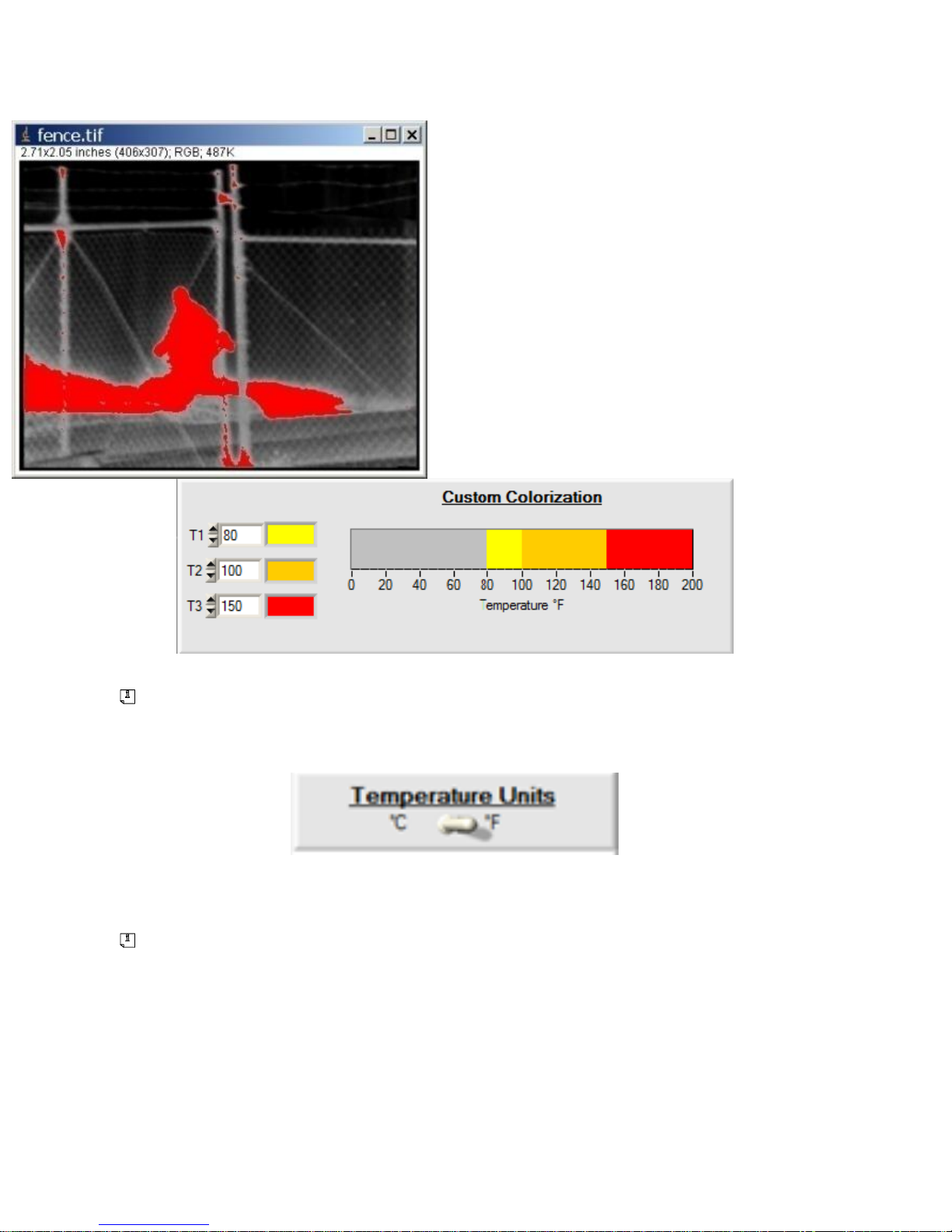
Hot Target Level II
Custom Colorization colorizes
the scene displayed based on the
temperature settings selected in the
Custom Colorization zone
Temperature units selected in the Temperature Units zone
applies to the temperature setting temperatures used in the
custom colorization settings.
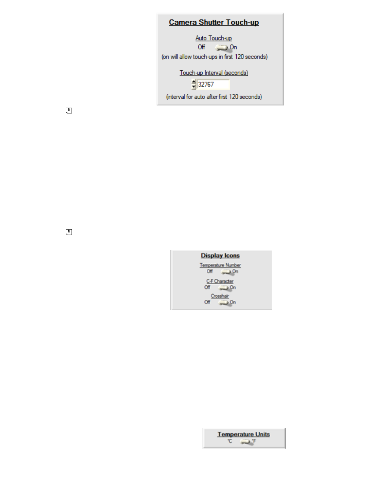
Manual Touch-up instructs the camera to perform a single point
non-uniformity correction. Auto Touch-up calibrations occur
periodically for the first 120 seconds as the camera is warming
up unless turned off by the user in Camera Shutter Touch-up
zone.
Page 25
25
Touch-up calibrations may improve image quality if the camera
has changed temperature or if the scene has drastically changed.
Default factory settings have Auto Touch-up enabled for the first
120 seconds (recommended) and then the max interval set after
that (32767 seconds). The camera automatically performs a
touchup when the camera changes temperature by 2°C. With
this setting one of the User Control Switch functions can be
assigned to perform Manual Touch-up for improved image
quality.
Display Icons turns symbology elements ON/OFF in the
display.
o Temperature Number displays the value of the
temperature reading in the scene. The temperature
reading is taken by sampling the center 4×4 pixels of
the scene. This is centered about the crosshair.
o C-F Character displays the units of the temperature
reading (C for degree Celsius and F for degree
Fahrenheit). The Temperature Units zone is used to
select the temperature units.
Page 26
26
o Crosshair turns on the + symbol in the center of the
display.
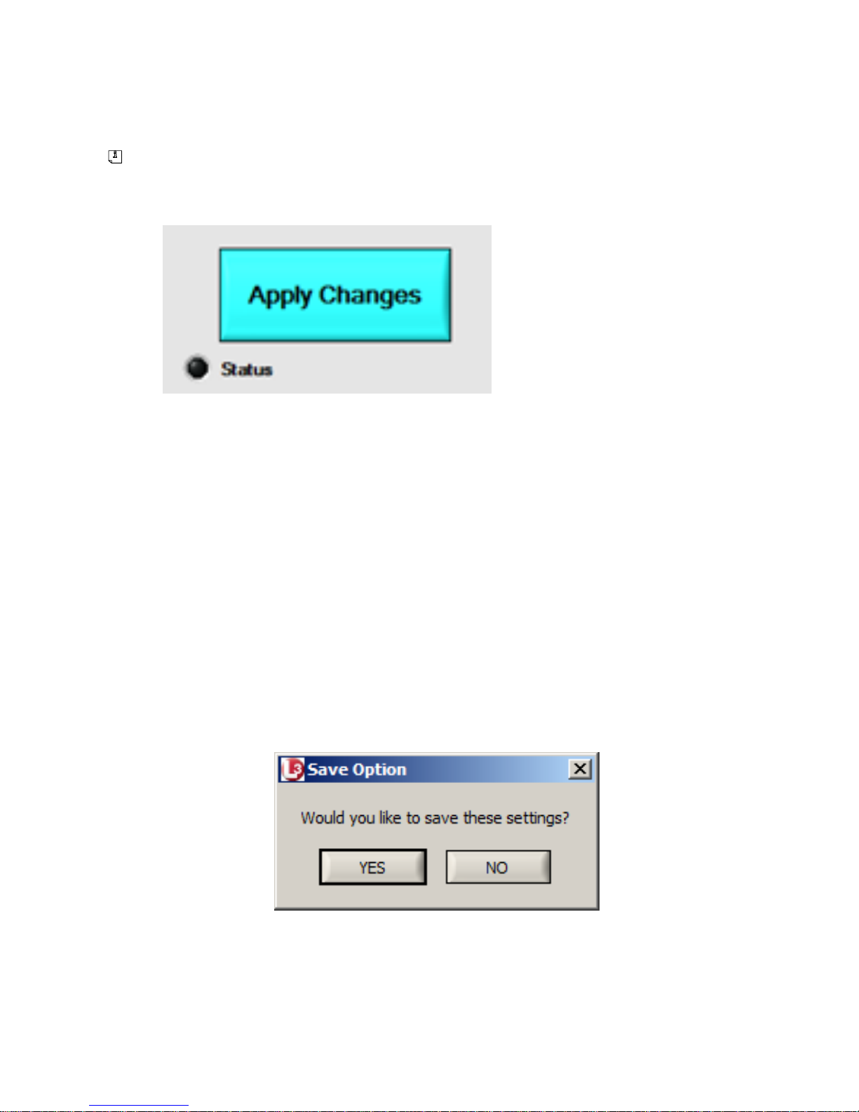
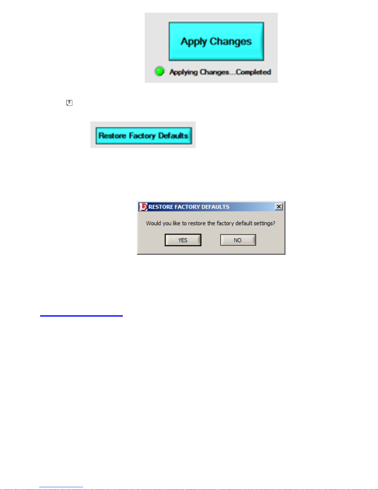
Apply Changes applies your changes to the camera and saves
them to camera memory so that it uses this configuration every
time the camera is powered up. To save your changes, click on
DO NOT DISCONNECT THE CAMERA FROM
THE COMPUTER OR REMOVE POWER WHILE
DATA IS BEING SAVED BY APPLY CHANGES.
IF THE CAMERA LOSES POWER WHILE DATA
IS BEING SAVED, THE CAMERA MEMORY
MAY BE CORRUPTED.
A message pops up to confirm that you want to save the changes
you have made.
Once the changes have been saved successfully the Status
symbol turns green and it is now safe to disconnect the camera.
Page 27
27
If you have made changes and would like to return to the
original factory settings, or if data has been corrupted
restores factory settings to the
camera.
A warning message appears asking you to confirm that you want
to return to factory settings.
You may also return to factory defaults without using the GUI
by holding down the User Control Switch for 5 seconds.
4. Accessories
Contact L-3 EOTech for accessories that are approved for use with
your Camera.
Accessory Video & Power Adapter
Common accessories for the camera are:
Page 28
28
Video/USB Cables
These may appear the same as common video/USB cables. However,
they are actually unique for the X320 and X640 Camera. Do Not
attempt to use other similar cables – they will not operate the camera,
and may cause damage
Operating With Video & External Power
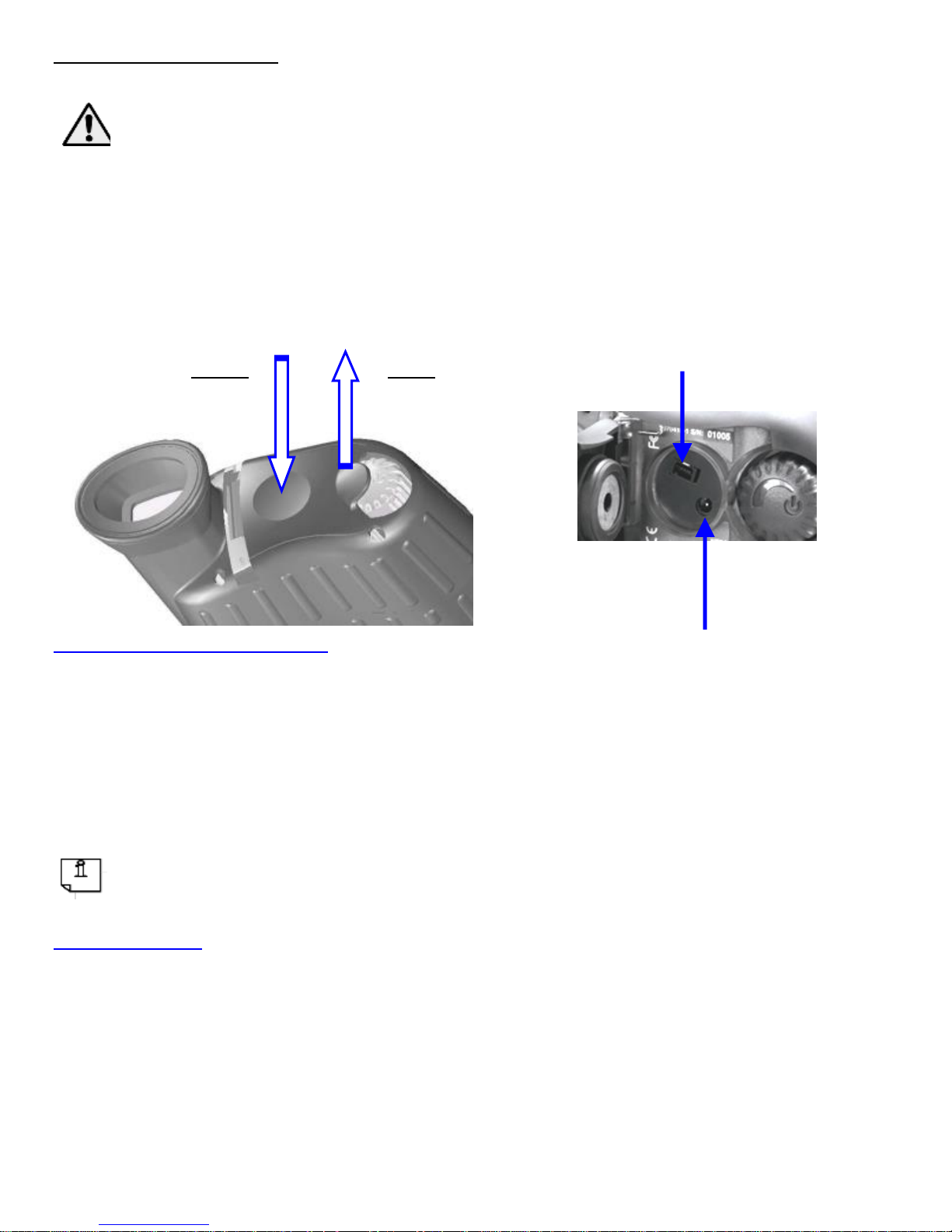
The External connections are located inside the Rear Plug.
AC/DC Power Adapter
Connect the AC/DC Power Adapter to the connector labeled
“Power”, and to AC power (wall outlet). If batteries are installed
and the AC/DC adapter is connected, the camera receives its power
from the AC/DC power adapter. It continues to monitor battery
voltage and will stop operating if the batteries are low
The AC/DC Power Adapter provides power to the camera –
however, it does not recharge batteries installed in the camera.
Video Cable
Connect the Video Cable to the connector labeled “Video”, and to a
Video Monitor or video recorder. When Connecting the Video
Cable, the video continues to be displayed on the internal LCD, so
that the user can monitor what is being recorded or displayed
externally. If the internal display is not being used, the brightness
should be set to minimum to extend battery life.
Power
Pull
To Open
Push
To Close
Power
Video
Page 29

29
4. Additional Information
Specifications
Detector
Type
Amorphous-Silicon Microbolometer
Spectral Response
7 to 14 microns
Thermal Performance
Time to Operation
~ 5 seconds
Contrast/Level
Automatic (Electronic Image Control)
Image Touch-up
Automatic (mechanical shutter)
Color Modes
White/Black Hot, HTL I, HTL II, and
Custom Color
Range to Detect Human
Activity
735 meters (X320/X640 25mm)
1000 meters (X640 35mm)
X320 Optics
Field of View
12° × 9°
Focal Length
25 mm
Focus Range
4 feet to infinity
X640 Optics
Field of View
24° × 18°
Focal Length
25 mm
Focus Range
4 feet to infinity
Field of View
18° × 13.5°
Focal Length
35 mm
Page 30

30
Focus Range
4 feet to infinity
Video
Viewfinder Display
Color LCD
Viewfinder Brightness
Adjustable (integral to on/off switch)
Auxiliary Video Out
Output jack on rear (NTSC format)
Power
Power
2 AA Lithium Batteries
Operating Time
2 hrs. Continuous operation (alkaline
batteries*) at room temperature; 6 hrs.
(lithium batteries) at room temperature
Auxiliary Power In
12Vdc (input jack on rear)
* The X320 and X640 can run on AA Alkaline batteries but performance and battery life may be
inconsistent.
Physical
Size
5 ½ x 4 ½ x 2 (inches)
14 x 11.4 x 5.1 (cm)
Weight
13oz. (369g) w/batteries (X320/X640 25mm)
14oz. (397g) w/batteries (X640 35mm)
Eye Cup
Integral to camera
Environmental
Operating Temperature
-20°C to +60°C
Storage Temperature
-20°C to +80°C*
Water Resistant
Yes, 1 meter submersion with both doors
closed
Buoyant
Yes, floats in water
Shock Resistant
Yes, 4 ft. drop in accordance with MILSTD-810G, Method 516.6, Procedure IV
EMC Compliance
FCC: part 15, class B
CE Mark: EN61000-6-1 & EN61000-6-3
Page 31

31
Features
Enhanced DSP Image Processing
On-screen battery level indicator
Left or Right Hand operation with rugged slip-resistant grip
Tactile Battery loading feature for night-time installations
Scene temperature readout and temperature-based colorization
Electronic zoom
Multiple colorization modes
Configurable function button
Standard Equipment
Carrying Case
2AA Lithium Batteries
Neck Strap & Wrist Strap
Lens Cleaning Cloth
Video/USB Cable
*Storage Temperature does not include batteries – always follow battery manufacturers’
recommendations for battery storage.
Specifications are subject to change without notice
Page 32

32
Frequently Asked Questions
Q1 Can different battery types be used?
A1 As long as the battery is an AA size, the user can install
Alkaline, NiMh Rechargeable, or Lithium. NOTE: The X320
OR X640 can run on AA Alkaline batteries but performance
and battery life may be inconsistent.
Q2 Why does my camera sometimes behave erratically?
A2 When batteries become very low, the camera may behave
erratically (i.e. video flashing, power cycles on & off, etc).
Replacing batteries is the most common cure to erratic
operations.
Q3 Is the Lens normally difficult to turn?
A3 Yes, the camera is manufactured with tight seals to make it
waterproof, which makes these seals difficult to turn.
Page 33

33
Trouble Shooting Guide
Problem
Possible Cause
Possible Remedy
After waiting
the 5 seconds of
warm up, the
video does not
appear and/or
the screen is
white or
flashing blue
Low Battery
Power
Replace Batteries
No Image in the
LCD display (no
logo, no battery
icon, and no
video or white
video)
The LCD Display
Brightness is too
low
Adjust the display
brightness by
turning the
on/switch clockwise
Batteries are low
Replace Batteries
or remove batteries
and use external
power
A solid blue
screen is
displayed.
Power transient
or static discharge
Turn camera off
and back on
Page 34

34
L-3 EOTech
Warranty
Product(s) will conform to L-3 EOTech’s current drawings and
specifications at the time of delivery and be free from defects in
material and workmanship under normal use and service for three
(3) years, beginning on the date the product is delivered to the
customer, (the “warranty”). L-3 EOTech’s sole obligation, buyer’s
exclusive remedy, under the warranty is for L-3 EOTech, at its
option, to repair or replace any part of the product which fails to meet
the warranty. For warranty repairs/replacements, customer shall
return product(s) to L-3 EOTech's facility through the RMA process
(see below). The warranty shall not apply to products; (i) used for
purposes for which they are not designated or intended, or (ii) which
have been repaired or altered without L-3 EOTech’s prior written
consent, or (iii) which have been subjected to misuse, negligence,
accident or improper maintenance or installation, or (iv) upon L-3
EOTech’s examination, do not disclose to L-3 EOTech’s satisfaction
nonconformance to the warranty.
NO OTHER WARRANTIES, EXPRESS OR IMPLIED, ARE
MADE WITH RESPECT TO THE PRODUCT(S) INCLUDING,
BUT NOT LIMITED TO, ANY IMPLIED WARRANTY OF
MERCHANTABILITY, NON-INFRINGENT OR FITNESS FOR
A PARTICULAR PURPOSE. IN NO EVENT SHALL L-3
EOTECH OR ITS LICENSORS BE LIABLE FOR INDIRECT,
INCIDENTAL OR CONSEQUENTIAL DAMAGES, LOSS OF
PROFITS, LOSS OF USE OR DATA OR INTERRUPTION OF
BUSINESS, WHETHER UNDER THEORIES IN TORT,
CONTRACT OR OTHERWISE, EVEN IF L-3 EOTECH OR ITS
LICENSORS HAVE BEEN ADVISED OF THE POSSIBILITY OF
SUCH DAMAGES.
Page 35

35
HOW TO RETURN PRODUCTS FOR REPAIR:
1. Do not return product to place of
purchase
2. Please complete the Return Authorization
Request off the EOTech Web Site at
www.eotech-inc.com/raform.php
3. Please advise Model, serial number, date of
purchase (proof of purchase may be
required) and a description of the problem
4. EOTech will issue you a Return Authorization
#
5. Clearly Mark the RA# on the outside of the box
and return to:
L-3 EOTech/ Infrared Products
Division RMA#___________
3414 Hermann Dr.
Garland TX 75041
NOTE: Consumer is responsible for shipping
expenses to service center
L-3 EOTech Customer Service Department: 1-888EOTHOLO
5002035-1 Rev J
Page 36

36
L-3 EOTech/ Infrared Products Division
3414 Hermann Dr.
Garland TX 75041
5002035-1 Rev J
Phone: 1-888-EOTHOLO
1-888- 368- 4656
 Loading...