

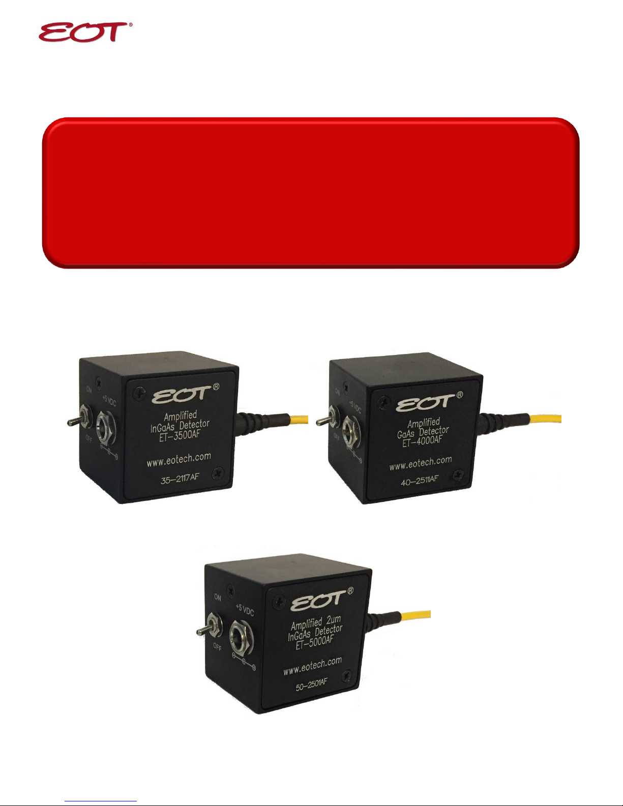
EOT ET-3500AF, ET-4000AF, ET-500AF User Manual
Amplified High Speed
User Guide
Fiber Photodetectors
(231)935-4044 ׀ (800)697-6782 ׀ sales@eotech.com ׀ www.eotech.com
Electro-Optics Technology, Inc.
3340 Parkland Ct. Traverse City, MI 49686 USA
Page 1 of 7
3mm
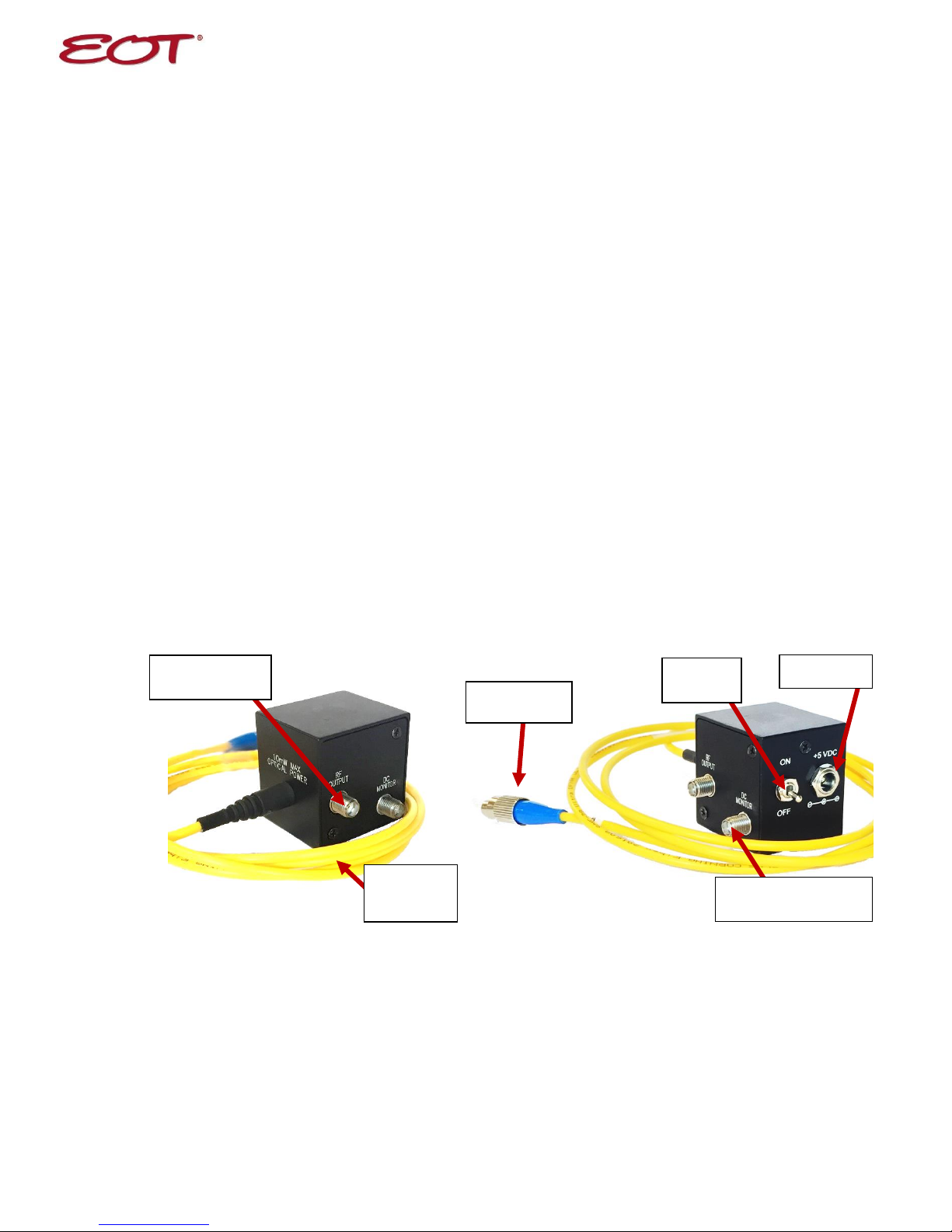
Furcation
Tubing
DC Monitor Output
(SMA)
FC
Connector
Signal Output
(SMA)
Power Jack
Power
Switch
EOT AMPLIFIED HIGH SPEED FIBER PHOTODETECTOR USER’S GUIDE
Thank you for purchasing your Amplified High Speed Fiber Photodetector from EOT. This user’s guide will
help answer any questions you may have regarding the safe use and optimal operation of your Photodetector.
TABLE OF CONTENTS
I. Amplified High Speed Fiber Photodetector Overview.................................................................................... 2
II. Operation of your EOT Amplified High Speed Fiber Photodetector .............................................................. 2
III. Troubleshooting ............................................................................................................................................... 3
IV. Drawings: Amplified High Speed Fiber Photodetectors ................................................................................. 4
V. Specifications: Amplified High Speed Fiber Photodetectors .......................................................................... 4
VI. Schematics: Amplified High Speed Fiber Photodetectors............................................................................... 5
VII. Warranty Statement and Repair ..................................................................................................................... 5
VIII. Glossary of Terms ......................................................................................................................................... 6
I. Amplified High Speed Fiber Photodetector Overview
EOT’s Amplified High Speed Fiber Photodetectors contain PIN photodiodes that utilize the photovoltaic
effect to convert optical power into an electrical current and a fixed gain transimpedance amplifier
allowing measurement of <1mW input powers. Figure 1 below identifies the main elements of your
Fiber Photodetector.
Figure 1: EOT Amplified High Speed Fiber Photodetector
When terminated into 50Ω into an oscilloscope, the pulsewidth of a laser can be measured. When
terminated into a spectrum analyzer, the frequency response of a laser can be measured.
II. Operation of your EOT Amplified High Speed Fiber Photodetector
A. Caution: Eye safety precautions must be followed when utilizing any equipment used in the vicinity
of laser beams. Laser beams may reflect from the surface of the detector or the optical mount and
caution must be exercised.
(231)935-4044 ׀ (800)697-6782 ׀ sales@eotech.com ׀ www.eotech.com
Electro-Optics Technology, Inc.
3340 Parkland Ct. Traverse City, MI 49686 USA
Page 2 of 7

B. Mount the detector to an optical stand by the mounting holes on the bottom of the detector housing.
C. Clean the end of the fiber ferrule and connect to the laser.
D. Connect the detector to the oscilloscope using a coaxial cable designed for 10GHz operation. The
DC Monitor cable can be a general purpose cable.
E. Use the 50Ω termination input of the oscilloscope.
F. Connect the DC Monitor to a high impedance device, such as a multimeter. Set the device to
millivolts or volts. The output of the DC Monitor converts the average photodiode current to a
voltage output of 1mV/uA. The DC Monitor output has an offset voltage of less than 70mV.
G. Note that the external power supply is a 5VDC regulated supply with a positive center pin. Using a
supply other than 5VDC could damage the detector.
H. After being certain that the damage threshold of the detector is not exceeded, turn on the laser.
III. Troubleshooting
A. No signal is seen the first time the detector is used.
1. Is the power switch on? Is the external power supply connected?
2. Is your signal a CW signal? If so, there will not be a signal output present because the detector is
AC coupled. There would be an output from the DC Monitor.
3. Be certain that the signal is not high off scale on the oscilloscope.
4. Is the wavelength of the laser within the spectral range of the detector?
5. Has a 50Ω termination input been used?
6. Make sure the fiber radius is greater than 1 inch. Inspect fiber for damage.
7. Check the end of the fiber ferrule for cleanliness or damage.
8. Is there enough light (see sensitivity spec on the data sheet) incident on the detector to generate a
signal?
B. A signal has been previously obtained, but not currently.
1. Try steps listed under A.
2. Recheck if the voltage is present at the external power supply plug.
(231)935-4044 ׀ (800)697-6782 ׀ sales@eotech.com ׀ www.eotech.com
3340 Parkland Ct. Traverse City, MI 49686 USA
Electro-Optics Technology, Inc.
Page 3 of 7
 Loading...