

Page 1
V0001
Multi-channel Audio/ Video Controller
Page 2

Name of Parts ·························· ·············· ·············· 3
Features Overview ·················· ················· ············ 4
Remote Control and Operating Instructions ······ ············· 5
Supplied Accessories ······························· ··············· 6
Function Parameters ······································ ··············· 9
Application wring diagram(Input) ··················
Application wring diagram(Output) ···················· ··
Page 3

Contents
Name of Parts ·························· ·············· ·············· 3
Features Overview ·················· ················· ············ 4
Remote Control and Operating Instructions ······ ············· 5
Supplied Accessories ······························· ··············· 6
··········· ········ 7
······ · ······ 8
Function Parameters ······································ ··············· 9
· ·········
·· ········
····
········
Application wring diagram(Input) ··················
Application wring diagram(Output) ···················· ··
·
2
Page 4
Features Overview
.1. Independent 4CH Audio & Video Input
2. Independent 4CH Audio & Video Output
3. Any one of the outputs can be selected as from either one of the input
Channels, with desired video input gain settings.
4. Wide working voltage, DC 12-24V, is given for applications in different vehicles
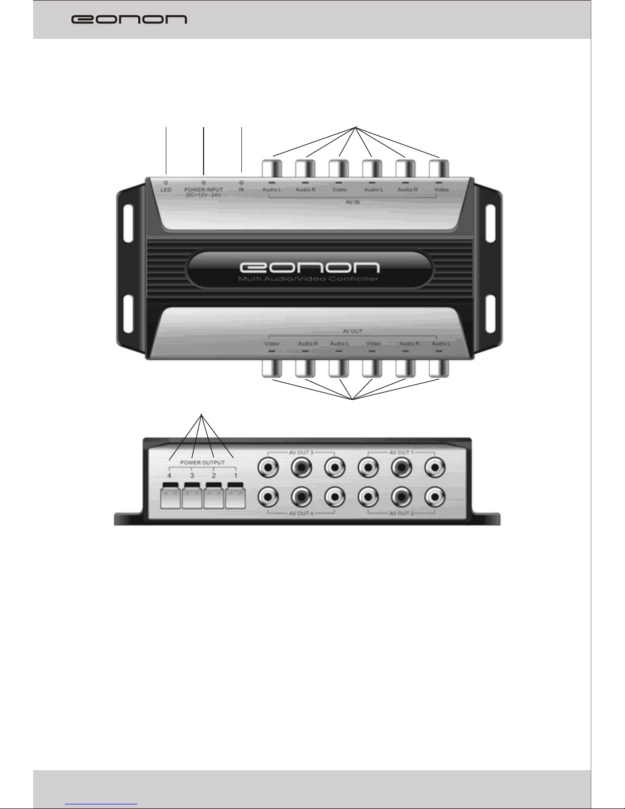
Name of Parts
1. Audio/ Video Input( RCA)
2. Audio/ Video Output( RCA)
3. IR remote Signal Input Interface
4. DC Power Input
5. LED Indicator
6. DC Power Output
3
③ ①
④
②
⑤
⑥
⑩
Page 5

Features Overview
.1. Independent 4CH Audio & Video Input
2. Independent 4CH Audio & Video Output
3. Any one of the outputs can be selected as from either one of the input
Channels, with desired video input gain settings.
4. Wide working voltage, DC 12-24V, is given for applications in different vehicles
4
Page 6

Supplied Accessories:
Please check and indentify the supplied accessories.
Remote Control 1 pc
Operation Manual
IR Receiver 1 pc
Power Cable
Installation Screws 5 pcs
Remote Control and Operating Instructions
1. POWER
LED indicates green after power is on. When power is off, LED indicates red.
By pressing the buttons of the remote control during power on, the LCD would
flash between red and green, and the buzzer would beep once.
2. RESET
By pressing the reset button, V0001 restores to default settings. That is, all
CH1~CH4 output channels are directed from input CH1 with 0 dB of video gain.
The input channel is CHI for the output channel CH1~CH4, and the video gain is 0
dB.
3. Output channel button
Output channel CH1~CH4 selection.
4. Input channel button
Pressing output channel button prior to input channel button makes the input and
output channel connected. For example, by pressing the output CH4 button first,
and then pressing the input Ch1 button can make CH4 output come from CH1
input.
5.Video gain
The Video gain of output channel is set to be either 0 dB or 6 dB. The Gain CH1~4
controls the output channel CH1~4 video gain, respectively. The value of video
gain depends on the output equipment connected. You can choose the video gain
you need according to the video effect after correctly connecting all devices
5
①
③
④
⑤
②
Operational Instructions:
1. Choose any output channel as desired output channel.
2. Ch oose co r respo nding in put cha nnel as de sired i n put cha nnel.
3. Set the gain for the output channel
Example:
How to set the signal of output channel CH4 to be input from the input channel
Ch1?
Press output CH4. Then press input CH1. After the output video works properly,
pressing Gain CH4 to set either 0 dB or 6 dB, in order to get better
performance.
Page 7

Supplied Accessories:
Please check and indentify the supplied accessories.
Remote Control 1 pc
Operation Manual
IR Receiver 1 pc
Power Cable
Installation Screws 5 pcs
··························································
······················································· 1 pc
································································
······························································ 1 pc
···················································
6
Operational Instructions:
1. Choose any output channel as desired output channel.
2. Ch oose co r respo nding in put cha nnel as de sired i n put cha nnel.
3. Set the gain for the output channel
Example:
How to set the signal of output channel CH4 to be input from the input channel
Ch1?
Press output CH4. Then press input CH1. After the output video works properly,
pressing Gain CH4 to set either 0 dB or 6 dB, in order to get better
performance.
Page 8

⑤
⑥
7. AV OUT1 Audio/ Video Output
8. AV OUT2 Audio/ Video Output
9. AV OUT3 Audio/ Video Output
10. AV OUT4 Audio/ Video Output
11. DC Power Output 12~24V
Application wring diagram(Input)
Video
Audio-R
Audio-L
Video
Audio-R
Audio-L
DVD1
DVD2
DVD4
DVD3
Video
Audio-R
Audio-L
1. AV IN1 Audio/ Video Input
2. AV IN2 Audio/ Video Input
3. AV IN3 Audio/ Video Input
4. AV IN4 Audio/ Video Input
5. DC Power Input 12~24V
6. IR remote Signal Input Interface
①
③
②
④
Video
Audio-R
Audio-L
7
Application wring diagram(Output)
Page 9

Monitor 2
⑦
⑧
Monitor 1
Monitor 3
Monitor 4
7. AV OUT1 Audio/ Video Output
8. AV OUT2 Audio/ Video Output
9. AV OUT3 Audio/ Video Output
10. AV OUT4 Audio/ Video Output
11. DC Power Output 12~24V
8
Application wring diagram(Output)
⑨
⑩
Page 10

Performance Parameters
Input voltage………………………………………… ………………….… DC 12-24V
Video input impedance……………………………… ……….……………….. 75 Ohm
Audio input impedance……………………………… …….…………………8.2k Ohm
Working temperature……………………………………………… ……0℃ ~ +70℃
Storage ………………………………… …………………. -30℃ ~ +80
Direct Current output(total 4 channels) ……………… ………MAX DC 4A
…..
…
…
…….
temperature … ℃
……………
9
Page 11

Page 12

 Loading...