

Page 1

Eonis
User Guide
21-inch clinical display
MDRC-2221
K5903500/04
19/09/2014
Page 2

Barco nv
President Kennedypark 35, 8500 Kortrijk, Belgium
Phone: +32 56.23.32.11
Fax: +32 56.26.22.62
Support: www.barco.com/esupport
Visit us at the web: www.barco.com
PrintedinBelgium
Page 3

Table of contents
TABLE OF CONTENTS
1. Welcome! ......... ............................................................ ..................... 3
1.1 About the product ............................................................................................. 3
1.2 What’s in the box.............................................................................................. 3
2. Parts, controls and connectors .................................. ............................. 5
2.1 Front view...................................................................................................... 5
2.2 Rear view ............. ................ ................ ................ ................ ................ ......... 6
3. Display installation ................... ........................................................... 7
3.1 Adjusting the display position....... ................ ................ ................ ................ ......... 7
3.2 Connecting the cables........................................................................................ 8
3.3 Kensington security slots..................................................................................... 8
3.4 VESA-mount installation ..................................................................................... 9
4. Daily operation ......... .................................................................... ...... 11
4.1 Recommendations for daily operation ................... ................ ................ ................ ...11
4.2 On/Off switching...................... ................ ................ .................. ................ .......12
4.3 Bringing up the OSD menus .......... ................ ................ ................ ................ .......12
4.4 Navigating through the OSD menus ..... ................ ................ ................ ................ ...12
5. Advanced operation .................. ........................................................... 13
5.1 Video input source selection.................................................................................13
5.2 Luminance adjustment ........ ................ ................ ................ .................. .............13
5.3 Gamma selection .............................................................................................13
5.4 Ambient light reading room selection .......................................................................14
5.5 White point selection..........................................................................................14
5.6 OSD menu language .... ................ ................ .................. ................ ................ ...15
5.7 Orientation.... ................ ................ ................ ................ ................ ................ .15
5.8 DPMS mode ........ ................ ................ ................ ................ ................ ...........16
5.9 Power status LED.............................................................................................16
5.10 Self calibration frequency ....................................................................................16
5.11 Factory reset............ ................ ................ ................ ................ ................ .......17
6. Maintenance ............. .................................................................... ...... 19
6.1 Cleaning instructions .........................................................................................19
7. Important information ......... .................................................................. 21
7.1 Safety information...... .................. ................ ................ ................ ................ .....21
7.2 Environmental information ...................................................................................23
7.3 Regulatory compliance information .......... ................ ................ ................ ............... 25
7.4 EMC notice ... ................ ................ ................ ................ ................ ................ .26
7.5 Explanation of symbols .............. .................. ................ ................ ................ .......29
7.6 Legal disclaimer ...............................................................................................31
7.7 Technical specifications ......................................................................................32
A. Trou bleshooting . ................................................................................. 35
A.1 Troubleshooting ...............................................................................................35
A.2 Warning signals ...............................................................................................35
K5903500 EONIS 19/09/2014
1
Page 4

Table of contents
2 K5903500 EONIS 19/09/2014
Page 5
1. Welcome!
1. WELCOME!
1.1 About the product
Consistent image quality
The Eonis display presents crisp, razor-sharp, high-contrast images. To guarantee image consistency at
all times, it features a unique front sensor that automatically aligns image quality every time the display is
turned on. This image consistency enhances collaboration: images always appear exactly like they are
supposed to, on every display, which spurs confident clinical decisions. Furthermore, specialists looking
at X-ray images will appreciate the built-in DICOM settings.
One-click quality assurance
Like Barco’s entire medical display range, the Eonis display line comes with Barco’s online MediCal
QAWeb service for quality assurance and remote asset management. Proving its superior value in
hospitals around the world, MediCal QAWeb provides automated quality assurance checks and detailed
reports. It makes it easy for healthcare IT to centrally and remo
the healthcare organization. Also for private practices, QAWeb further strengthens image consistency
and allows you to easily personalize your image.
tely manage and configure displays across
Features
• Front sensor automatically aligns image quality
• IPS panel ensures wide viewing angle
• MediCal QAWeb suite for networked quality assurance, calibrat
the exceptional, consistent image quality of the Eonis display
• Medical-grade certifications
• Sockets for Kensington lock makes the Eonis display safe for use in
• Flexible VESA mount for easy arm, wall or cart mounting
• Multiple inputs (DisplayPort, DVI, etc.) ensure the display’s flexible deployment
This manual further guides you through the different steps needed to install and use the Eonis display.
ion and asset management all add to
clinical environments
CAUTION: Read all the important safety information before installing and operating your
Eonis display . Please refer to the dedicated chapter in this user guide.
1.2 What’s in the box
Overview
Your Eonis comes with:
K5903500 EONIS 19/09/2014
3
Page 6

1. Welcome!
• this Eonis user guide
• a documentation CD containing multilingual user documentation
• a system CD containing MediCal QAWeb Agent
• a (set of) AC power cord(s) (depending on the region of operation)
•aDVIcable
•aDPcable
• a USB cable
• an external power supply
• an accessory bag (cleaning cloth, velcro cable routing strap)
Keep y our original packaging. It is designed for this display and is the ideal protection
during transport and storage.
4 K5903500 EONIS 19/09/2014
Page 7
2. Parts, controls and connectors
2. PARTS, CONTROLS AND
CONNECTORS
2.1 Front view
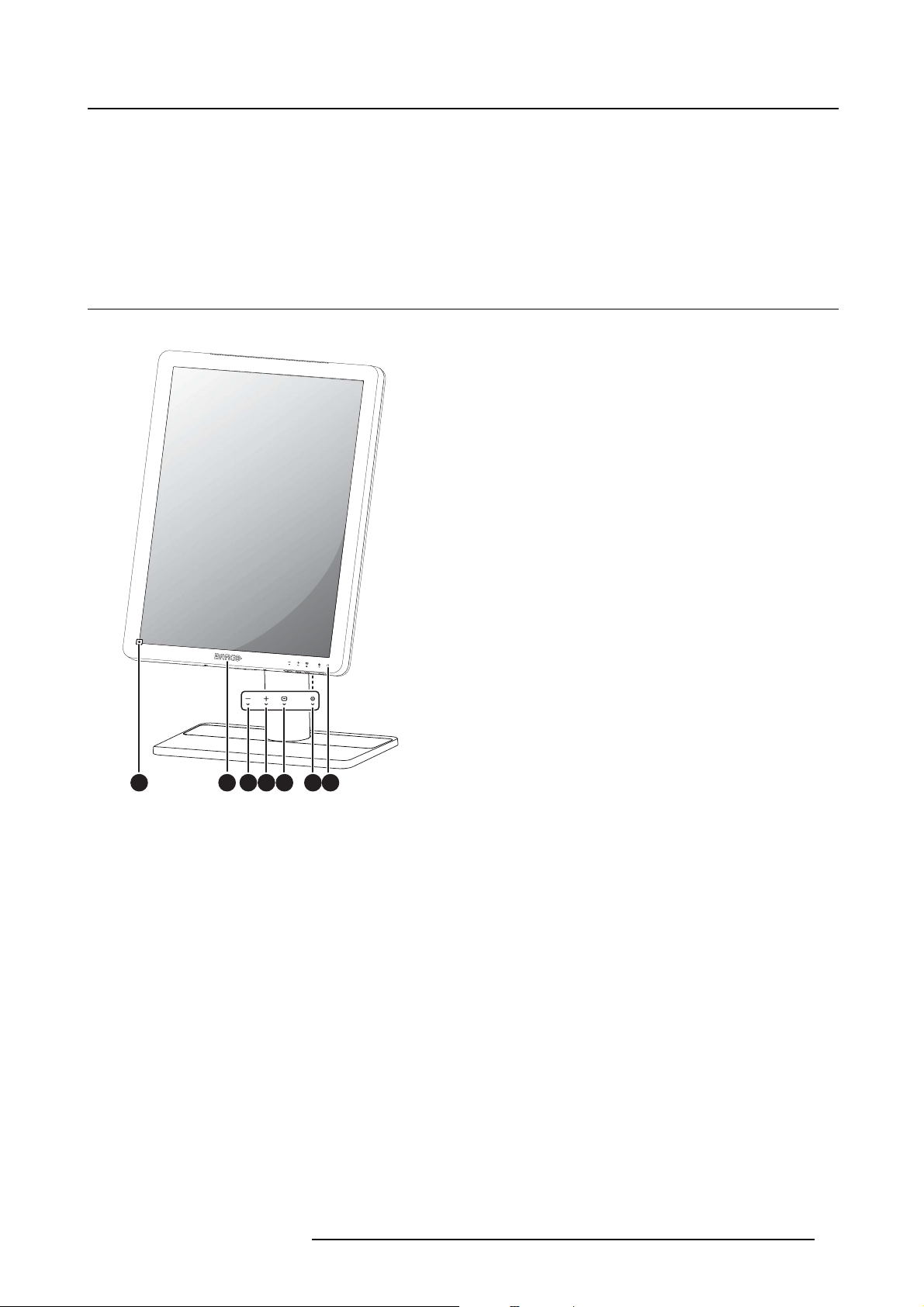
Overview
1 2 76543
Image 2-1
1. Front sensor
2. USB downstream connector
3. Left / Decrease key
4. Right / Increase key
5. Menu / Enter key
6. Standby key
7. Power status LED
K5903500 EONIS 19/09/2014
5
Page 8
2. Parts, controls and connectors
2.2 Rear view
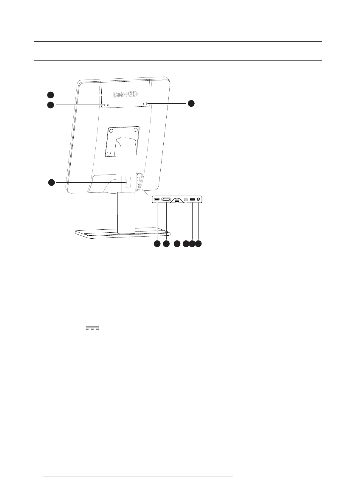
Overview
1
2
3
2
Image 2-2
1. Connector compartment cover
2. Kensington security slots
3. Opening for cable routing strap
4. DisplayPort input
5. DVI input
6. USB downstream connector
7. USB upstream connector
8. USB downstream connector
9. +24 VDC (
) power input
4 5 6 7
8 9
6
K5903500 EONIS 19/09/2014
Page 9
3. DISPLAY INSTALLATION
3.1 Adjusting the display position
To adjust the display position
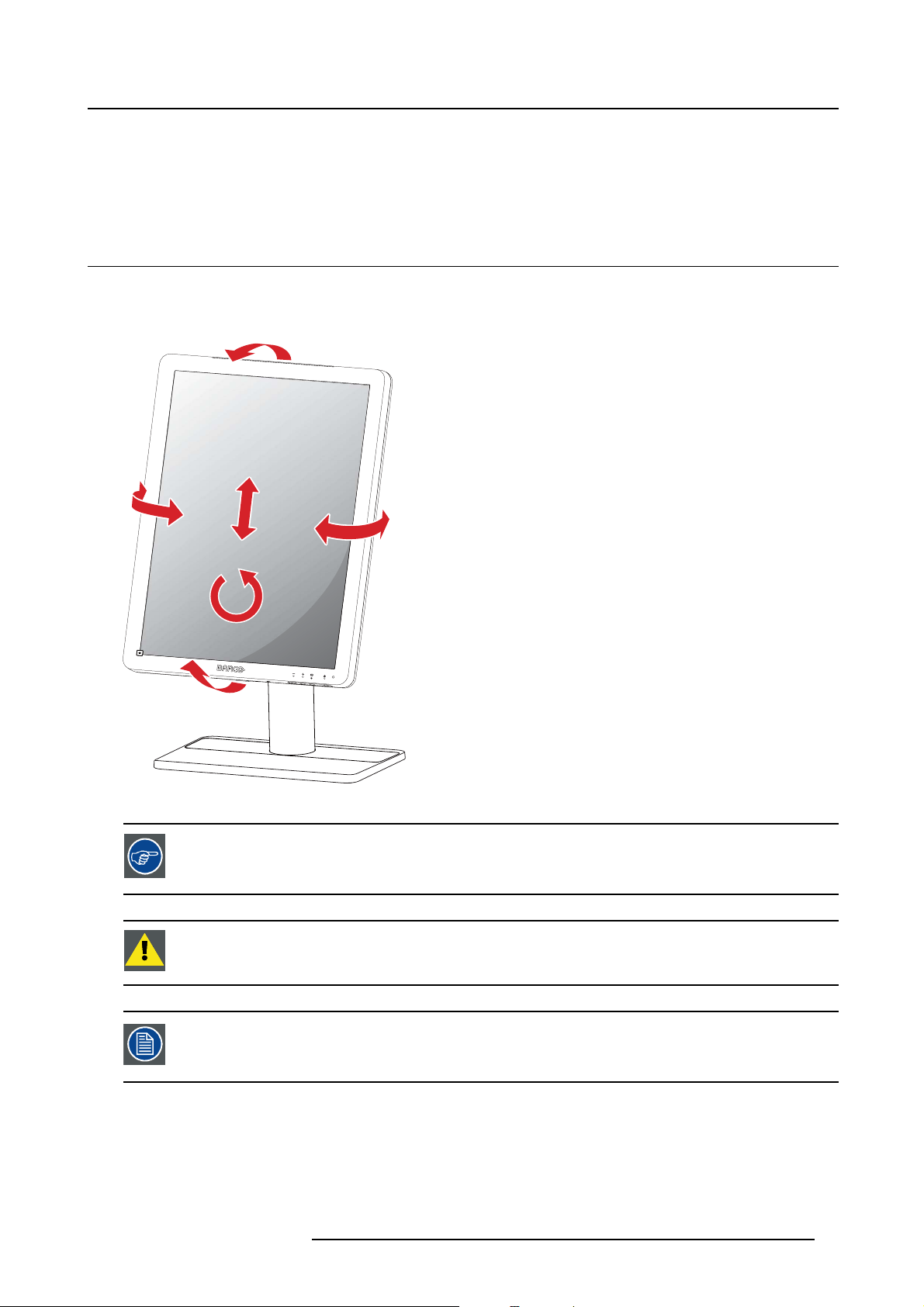
You can safely tilt, swivel, raise and lower your display as desired.
3. Display installation
Image 3-1
The standard orientation of the video input is landscape. If you use the display in portrait
mode, make sure you change the orientation of the video input via the screen settings
of the computer.
CAUTION: Do not try to pivot your display when attached to the stand. Trying to do so
could cause serious damage to your display and its stand.
It is expected behavior to have some movement between the LCD panel and the front
bezel of the display. This will have no impact on the functionality or reliability of the
display.
K5903500 EONIS 19/09/2014 7
Page 10
3. Display installation
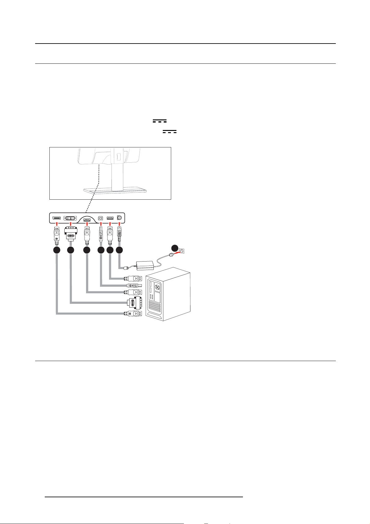
3.2 Connecting the cables
To connect the cables
1. Connect one or more of the video input connections of your display (DVI or DisplayPort) to the corre-
sponding video outputs on your computer or any other video device.
2. If you want to make use of the display’s USB downstream connectors, then connect your workstation
with the display’s USB upstream connector by means of the supplied USB cable.
3. Connect the supplied external DC (
4. Plug the other end of the external DC (
the proper power cord delivered with your display.
1 2 3 4 5 6
) power supply to the +24 VDC power input of your display.
7
) power supply into a grounded power outlet by means of
Image 3-2
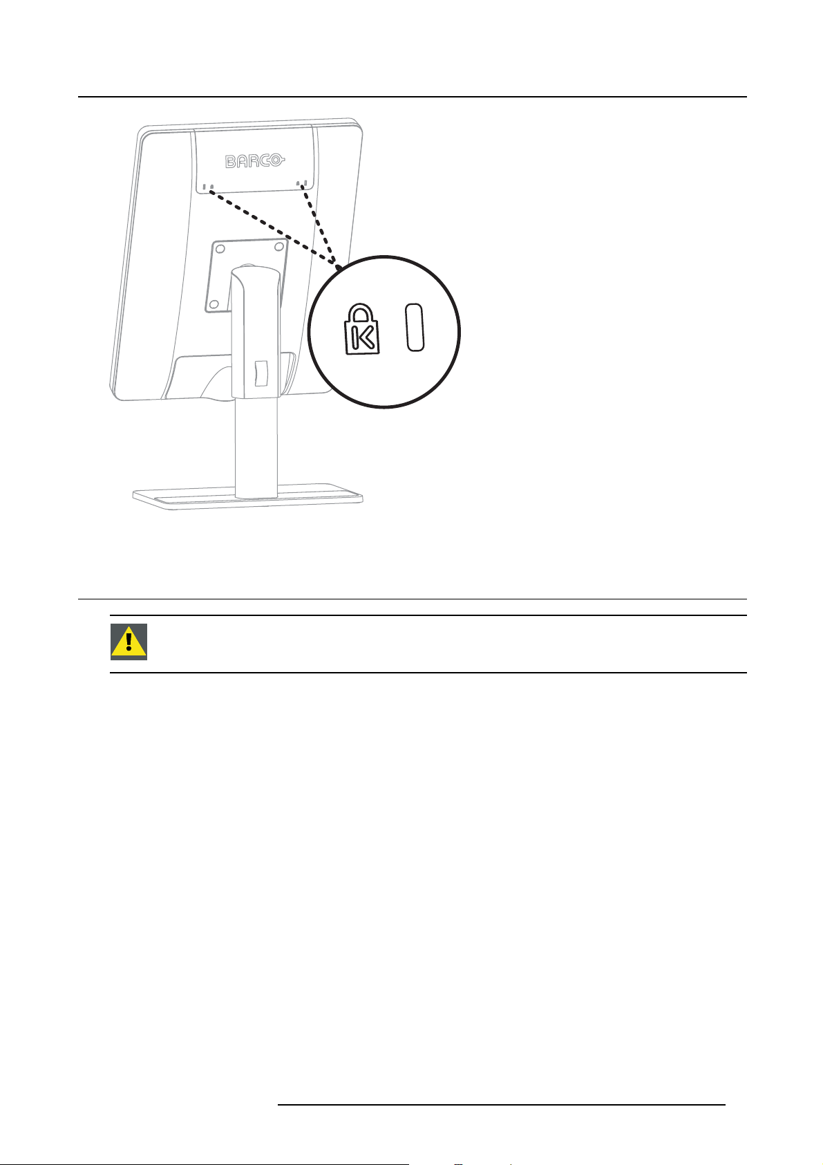
3.3 Kensington security slots
To make use of the Kensington securit
Your Eonis display has 2 Kensington slots available which allow you to secure the display to a desk or
any other fixed object.
8
yslots
K5903500 EONIS 19/09/2014
Page 11
3. Display installation
Image 3-3
3.4 VESA-mount installation
CAUTION: Use suitable mounting apparatus to avoid risk of injury.
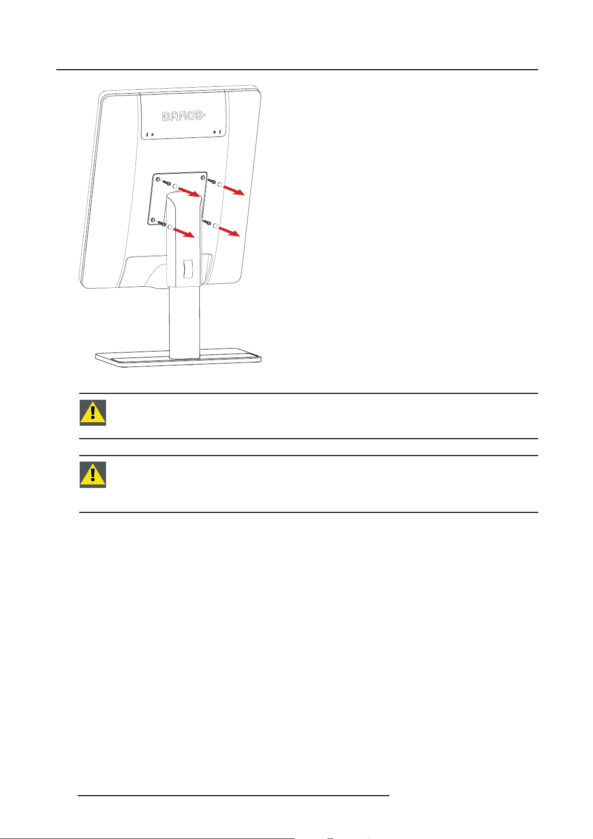
To mount the display on a VESA arm
The display panel, standard attached to a stand, is compatible with the VESA 100 mm standard.
1. Unscrew the four fixation screws to detach the panel from the stand.
2. Use 4 M4 screws to attach the panel to a VESA approved arm. Please make sure that the length of the
screws is 10mm + VESA plate thickness (tolerance of +/- 1 mm).
K5903500 EONIS 19/09/2014 9
Page 12
3. Display installation
Image 3-4
CAUTION: Use a n arm that can support a weight of at least 12 kg (26.50 lbs). Failure to
do so could make the panel fall, causing serious injur
damage to the equipment.
y to a child or adult, and s erio us
CAUTION: Never move a display attached to an arm by pulling or pushing the display
itself. I nstead, make sure that the arm is equipped with a VESA approved handle and
use this to move the display. Please refer to the instruction manual of the a rm for more
information and instructions.
10 K5903500 EONIS 19/09/2014
Page 13
4. Daily operation
4. DAILY OPERATION
4.1 Recommendations for daily op eration
Optimize the lifetime of your display
Enabling the Display Power Management System (DPMS) of your display will optimize its lifetime by automatically switching off the backlight when the display is not used for a specified period of time. By default,
DPMS is enabled on your display, but it also needs to be activated on your workstation. To do this, go to
“Power Options Properties” in the “Control Panel”.
Barco recommends setting DPMS activation after 20 minutes of non-usage.
Use a screen saver to avoid image retention
Prolonged operation of an LCD with the same content on the same screen area may result in a form of
image retention.
You can avoid or significantly reduce the occurrence of this phenomenon by using a screen saver. You
can activate a screen saver in the “Display properties” window of your workstation.
Barco recommends setting screen sa ver activation after 5 minutes of non-usage. A
good screen saver displays moving content.
In case you are working with the same image or an application with static image elements for several hours
continuously (so that the screen saver is not activated), change the image content regularly to avoid image
retention of the static elements.
Understand pixel technology
LCD displays use technology based on pixels. As a normal tolerance in the manufacturing of the LCD, a
limited number of these pixels may remain either dark or permanently lit, without affecting the performance
of the product. To ensure optimal product quality, Barco applies strict selection criteria for its LCD panels.
To learn more about LCD tec hnology and missing pixels, consult the dedicated white
papers available at w
ww.barco.com/healthcare.
Maximize quality assurance
QAWeb guarantees optimum and stabilized image quality in every private practice.
The front sensor on the Eonis works seamlessly with QAWeb to ensure a consistent image over time.
It automatically stabilizes the image from the moment you switch on the display. What’s more, QAWeb
provides you with instant feedback on the status of the display.
K5903500 EONIS 19/09/2014
11
Page 14

4. Daily operation
4.2 On/Off switching
To switch your display on or off
1. Shortly press the Standby ( )key.
4.3 Bringing up the OSD menus
About the OSD menu
TheOSDmenuallowsyoutoconfigure different settings to make your Eonis display fit your needs within
your working environment. Also, you can retrieve general information about your display and it
configuration settings through the OSD menu.
To bring up the OSD menu
1. While the display is switched on, press the Menu/Enter ( )key.
As a result, the OSD main menu comes up in the middle of the screen. If no further actions are taken
within the following 10 seconds however, the OSD menu will disappear again.
s current
4.4 Navigating through th e OSD menus
To navigate through the OSD menus
1. Use the Right/Down ( ) and Left/Up ( ) keys to move through the (sub)menus, change values or
make selections.
2. To go into a submenu or confirm adjustments and selections, use the Menu/Enter (
)key.
12
K5903500 EONIS 19/09/2014
Page 15

5. Advanced operation
5. ADVANCED OPERATION
5.1 Video in put source selection
About video input source selection
By default, your Eonis display automatically detects and shows the connected video input source. However, when for instance more then one video input source is connected, it may be needed to manually
select the input source to be displayed.
The available video input source selections for your display are:
• Auto: This is the default setting and will automatically detect and display the connected video input
source.
• DVI: This setting will display the video connected to the DVI input.
• DisplayPort: This setting will display the video connected to the DisplayPort input.
To select a video input source
1. Bring up the OSD main menu.
2. Navigate to the Input Selection menu.
3. Select one of the available video input sources.
5.2 Luminance adju stment
About luminance adjustment
The luminance of your Eonis display is adjustable over a predefined range. When you change the luminance, the display will adjust its backlight to reach the
target.
To adjust the luminance
1. Bring up the OSD main menu.
2. Navigate to the Adjustments menu.
3. Enter the Luminance submenu.
4. Set a luminance value as desired and confirm.
5.3 Gamma s election
About gamma selection
Native, uncorrected panels will display all grayscale/color levels with equal luminance increments. Studies
have shown however, that in medical images certain grayscale/color parts contain more relevant information than others. To respond to these conclusions, gamma functions have been defined. These functions
emphasize on these parts containing crucial information by correcting the native panel behavior.
The available gamma functions for your display are:
K5903500 EONIS 19/09/2014
13
Page 16

5. Advanced operation
• Native:IfyouselectNative, the native panel behavior will not be corrected.
• sRGB:Thisisthedisplayfunctionasdefined in the sRGB specificationandisdesignedtomatch
typical home and office viewing conditions. It is widely used in most computer applications.
• DICOM: DICOM (Digital Imaging and Communications in Medicine) is an international standard that
was developed to improve the quality and communication of digital images in radiology. In short,
the DICOM gamma function results in more visible grayscales in the images. Barco recommends
selecting the DICOM gamma function for most medical viewing applications.
• Gamma 2.2: Select this function in case the display is to replace a CRT display with a gamma of 2.2.
• QAWeb: This gamma function will be automatically selected when gamma functions are defined by
MediCal QAWeb.
To select a gamma function
1. Bring up the OSD main menu.
2. Navigate to the Adjustments menu.
3. Enter the Gamma submenu.
4. Select one of the available gamma functions.
5.4 Ambient light reading room selection
About ambient light reading rooms
The available ambient light reading rooms for your display are:
• Dark Room: Corresponds to light conditions in dark diagnostic reading rooms. This setting has the
lowest maximum ambient light.
• Office: Corresponds to light conditions in office rooms.
• Operation Room: Corresponds to light conditions in operating rooms. This setting has the highest
maximum ambient light.
• QAWeb: This setting will be automatically selected when ambient li
iCal QAWeb.
ght conditions are defined by Med-
To select an ambient light reading room
1. Bring up the OSD main menu.
2. Navigate to the Adjustments menu.
3. Enter the Ambient Light submenu.
4. Select one of the available reading rooms and confirm.
5.5 White poin t selection
About white point selection
This setting allows you to modify the display white point, used as reference for all other colors to be displayed.
The available white point settings for your display are:
• Native: The native, unmodified color temperature of the LCD panel.
• 6500K (sRGB): Corresponds to a color temperature of 6500 Kelvin (D65).
• QAWeb: This white point setting will be automatically selected when white point is defined by
MediCal QAWeb.
14
K5903500 EONIS 19/09/2014
Page 17

5. Advanced operation
To select the white point
1. Bring up the OSD main menu.
2. Navigate to the Adjustments menu.
3. Enter the White Point submenu.
4. Select one of the available white point presets.
5.6 OSD menu language
About the OSD menu lan guage
By default, the OSD menu comes up in English. However, there’s a wide range of other languages available for the OSD menu of your Eonis display:
•English
• French
•German
• Spanish
• Italian
•Dutch
• Japanese
• Traditional Chinese
•Simplified Chinese
• Korean
To select the language of the OSD menu:
1. Bring up the OSD main menu.
2. Navigate to the Adjustments > Settings menu.
3. Enter the Language submenu.
4. Select one of the available languages.
5.7 Orientation
About orientation
The orientation of the OSD menu can be adjusted to landscape or portrait.
To change the OSD orientation
1. Bring up the OSD main menu.
2. Navigate to the Adjustments > Settings menu.
3. Enter the Orientation submenu.
4. Select Portrait or Landscape as desired and confirm.
K5903500 EONIS 19/09/2014
15
Page 18
5. Advanced operation
5.8 DPMS mode
About DPMS mode
Enabling the Display Power Management System (DPMS) mode on your Eonis display will optimize the
displays’ lifetime by automatically switching off the backlight when no video signal is detected for approximately 10 seconds. The power status LED will then turn orange.
To enable/disable DPMS mode
1. Bring up the OSD main menu.
2. Navigate to the Adjustments > Settings > Power Save menu.
3. Enter the DPMS submenu.
4. Select On or Off as desired and confi rm.
5.9 Power statu s LED
About the power status LED
By default, the power status LED has the following behavior:
• Green: Displayison
• Blinking green: Display is entering standby power-saving mode
• Orange: Display is in standby power-saving mode
• Off: Display is disconnected from the mains power
This default behavior can be changed so that the power status LED is also off when the display is on or
when the display is entering standby power-saving mode.
To chan ge the behavior of the power status LED:
1. Bring up the OSD main menu.
2. Navigate to the Adjustments > Settings menu.
3. Enter the Power Status LED submenu.
4. Change the behavior of the power status LED as desired and confirm.
The orange standby power-saving state of the LED is not influenced by this setting. So,
when the display is in standby power-saving mode, the LED will turn orange, even if it
was switched off by this setting.
5.10 Self calibration frequency
About self calibration
The front sensor of your Eonis display measures the out
display to automatically stabilize its luminance for maximum image quality over the displays’ lifetime. This
self calibration is done at an adjustable, predefined frequency:
16
put luminance of your screen and allows the
K5903500 EONIS 19/09/2014
Page 19

5. Advanced operation
• 1min
• 1hr
• 3hr
• 24 hr
• Never
• QAWeb: This setting will be automatically selected when the self calibration frequency is defined by
MediCal QAWeb.
To adjust the self calibration frequency
1. Bring up the OSD main menu.
2. Navigate to the Adjustments > Settings menu.
3. Enter the Self Calibration Frequency submenu.
4. Select one of the available frequency presets.
5.11 Factory reset
About factory reset
A factory reset allows you to fully restore the display to its original factory setting.
To perform a factory reset
1. Bring up the OSD main menu.
2. Navigate to the Adjustments > Settings menu.
3. Enter the Factory Reset submenu.
4. Select Yes or No as desired and confirm.
K5903500 EONIS 19/09/2014
17
Page 20

5. Advanced operation
18 K5903500 EONIS 19/09/2014
Page 21
6. Maintenance
6. MAINTENANCE
General maintenance information
The Eonis does not require any scheduled maintenance or calibration activities. We recommend to use
QAWeb with the Barco default tests and frequencies to calibrate and maintain the display or return the
display to a Barco approved maintenance organization. In any case of doubts, contact the Barco Healthcare Division
6.1 Cleaning instructions
To clean the display
Clean the display using a sponge, cleaning cloth or soft tissue, lightly moistened with plai
Do not use following products:
• Alcohol/solvents at higher concentration > 5%
• Strong alkalis lye, strong solvents
•Acid
• Detergents with fluoride
• Detergents with ammonia
• Detergents with abrasives
• Steel wool
• Sponge with abrasives
• Steel blades
• Cloth with steel thread
CAUTION: Take care not to da mage or scratch the front glass or LCD. Be careful with
rings or other jewelry and do not apply excessive pressure on the front glass or LCD.
CAUTION: Do not apply or spray liquid directly to the display as excess liquid may cause
damage to internal electronics. Instead, apply the liquid to a cleaning cloth.
nwater.
K5903500 EONIS 19/09/2014 19
Page 22

6. Maintenance
20 K5903500 EONIS 19/09/2014
Page 23

7. IMPORTANT INFORMATION
7.1 Safety information
General recommendations
Read the safety and operating instructions before operating the device.
Retain safety and operating instructions for future reference.
Adhere to all warnings on the device and in the operating instructions manual.
Follow all instructions for operation and use.
Electrical Shock or Fire Hazard
To prevent electric shock or fire hazard, do not remove cover.
No serviceable parts inside. Refer servicing to qualified personnel.
Do not expose this apparatus to rain or moisture.
7. Important information
Modifications to the unit:
Do not modify this equipment without authorization of the manufacturer.
Type of p rotection (electrical):
Display with external power supply: Class I equipment.
Degree of safety (flammable anesthetic mixture):
Equipment not suitable for use in the presence of a flammable anesthetic mixture
or nitrous oxide.
with air or with oxygen
Non-patient care equipment
• Equipment primarily for use in a health care facility that is i
is unlikely (no applied part).
• The equipment may not be used with life support equipment.
• The user should not touch the equipment, nor its signal input por
and the patient at the same time.
Power connection – Equipment with external 24 VDC power suppl
• Power requirements: The equipment must be powered using the d
(
) SELV power supply.
• The medical approved DC (
• The power supply is specified as a part of the ME equipme
system.
• To avoid the risk of electric shock, this equipment must only be connected to a supply mains with
protective earth.
• The equipment should be installed near an easily accessible outlet.
• The equipment is intended for continuous operation.
) power supply must be powered by the AC mains voltage.
ntended for use where contact with a patient
ts (SIP)/signal output ports (SOP)
y
elivered medical approved 24 VDC
nt or combination is specified as a ME
Transient over-voltage
If the device is not used for a long time, disconnect it from the AC inlet to avoid damage by transient
over-voltage.
K5903500 EONIS 19/09/2014
21
Page 24

7. Important information
To fully disengage the power to the device, please disconnect the power cord from the AC inlet.
Power cords:
• Do not overload wall outlets and extension cords as this may result in fire or electric shock.
• Mains lead protection (U.S.: Power cord): Power cords should be routed so that they are not likely to
be walked upon or pinched by items placed upon or against them, paying particular attention to cords
at plugs and receptacles.
• The power supply cord should be replaced by the designated operator only at all time.
• Use a power cord that matches the voltage of the power outlet, which has been approved and complies
with the safety standard of your particular country.
Grounding reliability
Grounding reliability can only be achieved when the equipment is connected to an equivalent receptacle
marked “Hospital Only” or “Hospital Grade” (located on product or power supply cord)
External equipment
External equipment intended for connection to signal input/output or other connectors, shall comply with
relevant UL/ EN/ IEC standard (e.g. UL/EN/IEC 60950 for IT equipment and ANSI/AAMI ES/EN 60601-1
/ IEC 60601 series for medical electrical equipment). In addition, all such combinations -systems- shall
comply with the standard IEC 60601-1, safety requirements for medical electrical systems. Equipment
not complying with ANSI/AAMI ES/EN / IEC 60601-1 shall be kept outside the patient environment, as
defined in the standard.
Equipment not complying with IEC 60601 must be kept outside the patient environment, as definedinthe
standard as at least 1.5 meters from the patient or the patient support.
Any person who connects external equipment to signal input, signal output, or other connectors has formed
a system and is therefore responsible for the system to comply with the requirements of IEC 60601-1. If
in doubt, speak with a qualified technician.
In locations where 240 V outlets are used, connect this display only on a center-tapped, 240 V , singlephase supply.
Water and moisture
Never expose the device to rain or moisture. Never use the device near water - e.g. near a bathtub,
washbasin, swimming pool, kitchen sink, laundry tub or in a wet basement.
IP-x level for MDRC-2221
Ventilation
Do not cover or block any ventilation openings in the cover of the set. When installing the device in a
cupboard or another closed location, heed the necessary space between the set and the sides of the
cupboard.
Installation
Place the device on a flat, solid and stable surface that can support the weight of at least 3 devices. If you
use an unstable cart or stand, the device may fall, causing serious injury to a child or adult, and serious
damage to the device.
This apparatus conforms to:
CE (MDD 93/42/EEC class I product), CE-2004/108/EC, 2014/30/EU (Directive 2004/108/EC is
repealed with effect from 20 April 2016), IEC 60601-1:2005, ANSI/AAMI ES60601-1 (2005/(R)2012 +
C1:2009/(R)2012 + A2:2010/(R)2012), CAN/CSA-C22.2 No. 60601-1 (2008), DEMKO - EN 606011:2006, EN 60601-1-2:2007, EN60601-1:2006+A11:2011, KC, VCCI, FCC class B, ICES-001 Level B,
FDA Class I device, RoHS.
22
K5903500 EONIS 19/09/2014
Page 25
7. Important information
National Scandinavian Deviations for CL. 1.7.2:
Finland: "Laite on liitettävä suojamaadoituskoskettimilla varustettuun pistorasiaan"
Norway: "Apparatet må tilkoples jordet stikkontakt"
Sweden: "Apparaten skall anslutas till jordat uttag"
7.2 Environmental in formation
Disposal Information
Waste Electrical and Electronic Equipment
This symbol on the product indicates that, under the European Directive 2012/19/EU governing
waste from electrical and electronic equipment, this product must not be disposed of with other municipal
waste. Please dispose of your waste equipment by handing it over to a designated collection point for the
recycling of waste electrical and electronic equipment. To prevent possible harm to the environment or
human health from uncontrolled waste disposal, please separate these items from other types of waste
and recycle them responsibly to promote the sustainable reuse of material resources.
For more information about recycling of this product, please contact your local city office or your municipal
waste disposal service.
For details, please visit the Barco website at: h
ttp://www.barco.com/en/AboutBarco/weee
Turkey RoHS compliance
Türkiye Cumhuriyeti: AEEE Yönetmeliğine Uygundur.
[Republic of Turkey: In conformity with the WEEE Regulation]
中国大陆 RoHS
Chinese Mainland RoHS
根据中国大陆《电子信息产品污染控制管理办法》(也称为中国大陆RoHS), 以下部分列出了Barco产品
中可能包含的有毒和/或有害物质的名称和含量。中国大陆RoHS 指令包含在中国信息产业部MCV标准:
“电子信息产品中有毒物质的限量要求”中。
According to the “China Administration on Control of Pollution Caused by Electronic Information Products”
(Also called RoHS of Chinese Mainland), the table below lists the names and contents of toxic and/or
hazardous substances that Barco’s product may contain. The RoHS of Chinese Mainland is included in
the MCV standard of the Ministry of Information Industry of China, in the section “Limit Requirements of
toxic substances in Electronic Informa
零件项目(名称)
tion Products”.
有毒有害物质或元素
Component name
印制电路配件
Printed Circuit Assemblies
液晶面板
LCD panel
K5903500 EONIS 19/09/2014 23
Hazardous substances and elements
铅
Pb
X
X
汞
Hg
OOOOO
OOOOO
镉
Cd
六价铬
Cr6+
多溴联苯
PBB
多溴二苯
醚
PBDE
Page 26
7. Important information
零件项目(名称)
Component name
外接电(线)缆
External Cables
內部 线路
Internal wiring
金属外壳
Metal enclosure
塑胶外壳
Plastic enclosure
散热片(器)
Heatsinks
电源供应器
Power Supply Unit
风扇
Fan
文件说明书
有毒有害物质或元素
Hazardous substances and elements
铅
Pb
X
OO O O OO
OO O O OO
OO O O OO
OO O O OO
X
OO O O OO
OO O O OO
汞
Hg
OOOOO
OOOOO
镉
Cd
六价铬
Cr6+
多溴联苯
PBB
多溴二苯
醚
PBDE
Paper Manuals
光盘说明书
CD manual
O: 表示该有毒有害物质在该部件所有均质材料中的含量均在 SJ/T 11363-2006 标准规定的限量要求以下.
O: Indicates that this toxic or hazardous substance contained in all of the homogeneous materials for
this part is below the limit requirement in SJ/T11363-2006.
X: 表示该有毒有害物质至少在该部件的某一均质材料中的含量超出 SJ/T 11363-2006 标准规定的
限量要求.
X: Indicates that this toxic or hazardous substance contained in at least one of the homogeneous
materials used for this part is above the limit req
在中国大陆销售的相应电子信息产品(EIP)都必须遵照中国大陆《电子信息产品污染控制标识要求》标准
贴上环保使用期限(EFUP)标签。Barco 产品所采用的EFUP标签(请参阅实例,徽标内部的编号使用于制
定产品)基于中国大陆的《电子信息产品环保使用期限通则》标准。
All Electronic Information Products (EIP) that are sold within Chinese Mainland must comply with the
“Electronic Information Products Pollution Control Labeling Standard” of Chinese Mainland, marked with
the Environmental Friendly Use Period (EFUP) logo. The number inside the EFUP logo that Barco uses
(please refer to the photo) is based on the “Standard of Electronic Information Products Environmental
Friendly Use Period” of Chinese Mainland.
OO O O OO
uirement in SJ/T11363-2006
10
ChinaEnergyLabel
If there is a China Energy Label on your packaging or product, the product meets the following energy
requirements corresponding with the energy efficiency level on the label.
24
K5903500 EONIS 19/09/2014
Page 27

7. Important information
按照中国 << 能源效率标识管理办
法>>
In accordance with The Regulation
of the Implementation on China
Energy Label
能源效率等级
Energy Efficiency Level
能源效率
Energy Efficiency (cd/W)
关闭状态能耗
Energy Consumption in off mode
(W)
执行的能源效率国家标准编号
Code of National Standard applied
本显示器符合以下要求
This monitor is compliant with the
following requirements
12
>1.05 >0.85
<0.5 <1.0
GB 21520 GB 21520
本显示器符合以下要求
This monitor is compliant with the
following requirements
7.3 Regulatory compliance information
Indications for use
This display is an AMLCD display designed for viewing medical X-ray images. This unit should not be
used near patients (where patients are likely to be in unconscious condition) and should be kept outside
of 1.83 m perimeter and 2.29 m vertical.
FCC class B
This device complies with Part 15 of the FCC Rules. Operation is subject to the following two conditions:
(1) this device may not cause harmful interference, and (2) this device must accept any interference received, including interference that may cause undesired operation.
This device has been tested and found to comply with the limits for a Class B digital device, pursuant to
Part 15 of the FCC Rules. These limits are designed to provide reasonable protection against harmful
interference in a residential installation. This device generates, uses and can radiate radio frequency
energy and, if not installed and used in accordance with the instructions, may cause harmful interference
to radio communications. However, there is no guarantee that interference will not occur in a particular
installation. If this device does cause harmful interference to radio or television reception, which can be
determined by turning the device off and on, the user is encouraged to try to correct the interference by
one or more of the following measures:
• Reorient or relocate the receiving antenna.
• Increase the separation between the device and receiver.
• Connect the device into an outlet on a circuit different from that to which the receiver is connected.
• Consult the dealer or an experienced radio/TV technician for help.
Changes or modifications not expressly approved by the party responsible for compliance could void the
user’s authority to operate the equipment.
Canadian notice
This ISM device complies with Canadian ICES-001.
Cet appareil ISM est conforme à la norme NMB-001 du Canada.
K5903500 EONIS 19/09/2014
25
Page 28

7. Important information
7.4 EMC notice
General information
No specific requirement on the use of external cables or other accessories except power supply.
With the installation of the device, use only the delivered power supply or a spare part provided by the
legal manufacturer. Using another can result in a decrease of the immunity level of the device.
Electromagnetic emissions
The Eonis is intended for use in the electromagnetic environment specified below. The customer or the
user of the Eonis should assure that it is used in such an environment.
Emissions test Compliance Electromagnetic environment –
Guidance
RF emissions
CISPR 11
RF emissions
CISPR 11
Harmonic emissions
IEC 61000-3-2
Voltage fluctuations/ flicker
emissions
IEC 61000-3-3
Group 1 The Eonis uses RF energy only
for its internal function. Therefore,
its RF emissions are very low
and are not likely to cause any
interference in nearby electronic
equipment.
Class B
Class D
Complies
The Eonis is suitable for use
in all establishments, including
domestic establishments and
those directly connected to the
public low-voltage power supply
network that supplies buildings
used for domestic purposes.
This Eonis complies with appropriate medical EMC standards on emissions to, and interference from surrounding equipment. Operation is subject to the following two conditions: (1) this device may not cause
harmful interference, and (2) this device must accept any interference received, including interference that
may cause undesired operation.
Interference can be determined by turning the equipment off and on.
If this equipment does cause harmful interference to, or suffer from harmful interference of, surrounding
equipment, the user is encouraged to try to correct the interference by one or more of the following measures:
• Reorient or relocate the receiving antenna or equipment.
• Increase the separation between the equipment and receiver.
• Connect the equipment into an outlet on a circuit different from that to which the receiver is connected.
• Consult the dealer or an experienced technician for help.
Electromagnetic immunity
The Eonis is intended for use in the electromagnetic environment specified below. The customer or the
user of the Eonis should assure that it is used in such an environment.
Immunity test
Electrostatic discharge
(ESD)
IEC 61000-4-2
IEC 60601
Test levels
± 6kV contact
±8kVair
Compliance level
± 6kV contact
±8kVair
Electromagnetic
environment –
guidance
Floors should be wood,
concrete or ceramic tile.
If floors are covered with
synthetic material, the
relative humidity should
be at least 30%
26 K5903500 EONIS 19/09/2014
Page 29

7. Important information
Immunity test
Electrical fast
transient/burst
IEC 61000-4-4
Surge
IEC61000-4-5
Voltage dips, short
interruptions and voltage
variations on power
supply input lines
IEC 61000-4-11
Power frequency (50/60
Hz) magnetic field
IEC 61000-4-8
Conducted RF
IEC 61000-4-6
Radiated RF
IEC 61000-4-3
IEC 60601
Test levels
± 2kV for power supply
lines
± 1kV for input/ output
lines
± 1 kV line(s) to line(s)
± 2 kV line(s) to earth
<5%U
U
T
40% U
1
(> 95% dip in
T
) for 0.5 cycle
(60%dipinUT)
T
for 5 cycles
70% U
(30%dipinUT)
T
for 25 cycles
<5%U
) for 5s
U
T
(>95% dip in
T
3A/m
3Vrms
150 kHz to 80 MHz
3V/m
80 MHz to 2.5 GHz
Compliance level
± 2kV for power supply
lines
± 1kV for input/ output
lines
± 1 kV line(s) to line(s)
±2kVline(s)toearth
<5%U
U
) for 0.5 cycle
T
40% U
(> 95% dip in
T
(60% dip in UT)
T
for 5 cycles
70% U
(30% dip in UT)
T
for 25 cycles
<5%U
)for5s
U
T
Not applicable
(>95% dip in
T
2
3V
3V/m
Electromagnetic
environment –
guidance
Mains power quality
should be that of a typical
commercial or hospital
environment
Mains power quality
should be that of a typical
commercial or hospital
environment
Mains power quality
should by that of a
typical commercial or
hospital environment. If
the user of the Eonis
requires continued
operation during power
mains interruptions, it is
recommended that the
Eonis be powered from
an uninterruptible power
supply or a battery.
Power frequency
magnetic fields should
be at levels characteristic
of a typical location in
a typical commercial or
hospital environment.
Portable and mobile
RF communications
equipment should be
used no closer to
any part of the Eonis,
including cables, than
the recommended
separation distance
calculated from the
equation applicable
to the frequency
of the transmitter.
Recommended
separation distance
d=1.2√P
d=1.2√P 80 MHz to 800
MHz
d=2.3√P 800 MHz to 2.5
Ghz
Where P is the maximum
output power rating
of the transmitter in
watts (W) according
to the transmitter
manufacturer and d
is the recommended
1. is the a.c. mains voltage prior to application of the test level.
2. Eonis doesn’t contain susceptible components to magnetic fields
K5903500 EONIS 19/09/2014 27
Page 30
7. Important information
Immunity test
At 80 MHz and 800 MHz, the higher frequency range applies.
IEC 60601
Test levels
Compliance level
Electromagnetic
environment –
guidance
separation distance in
meters (m).
Field strengths from
fixed RF transmitters,
as determined by an
electromagnetic site
survey,
3
should be less
than the compliance
level in each frequency
4
range.
Interference may occur in
the vicinity of equipment
marked with symbol:
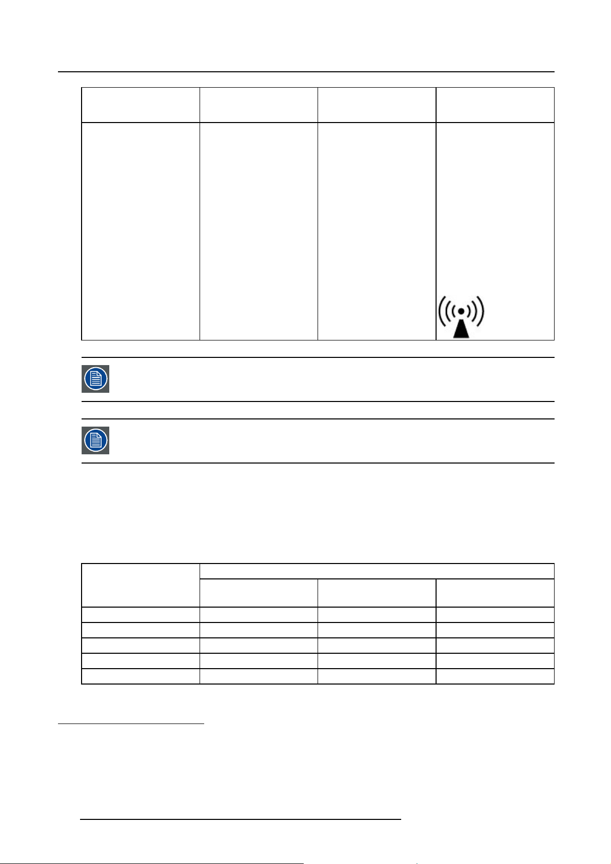
These guidelines may not apply in all situations. Electromagnetic propagation is affected by absorption and reflection from structures, objects and people.
Recommended separation distance
The Eonis is intended for use in an electromagnetic environment in which radiated RF disturbances are
controlled. The customer of the user of the Eonis can help prevent electromagnetic interference by maintaining a minimum distance between portable and mobile RF communications equipment (transmitters)
and the Eonis as recommended below, according to the maximum output power of the communications
equipment.
Rated maximum output
power of transmitter
W
0.01 0.12 0.12 0.23
0.1 0.38 0.38 0.73
1 1.2 1.2 2.3
10 3.8 3.8 7.3
100121223
3. Field strengths from fixed transmitters, such as base stations for radio (cellular/cordless) telephones and land mobile radios, amateur
radio, AM and FM radio broadcast and TV broadcast cannot be predicted theoretically with accuracy. To assess the electromagnetic
environment due to fixed RF transmitters, an electromagnetic site survey should be considered. If the measured field strength in the
location in which the Eonis is used exceeds the applicable RF compliance level above, the Eonis should be observed to verify normal
operation. If abnormal performance is observed, additional measures may be necessary, such as re-orienting or relocating the Eonis.
4. Over the frequency range 150 kHz to 80 MHz, field strengths should be less than3V/m.
5. For transmitters rated at a maximum output power not listed above, the recommended separation distance d in meters (m) can be
estimated using the equation applicable to the frequency of the transmitter. Where P is the maximum output power rating of the
transmitter in watts (W) according to the transmitter manufacturer.
Separation distance according to frequency of transmitter
5
150kHz to 80MHz
d=1.2√P
80MHz to 800MHz
d=1.2√P
800MHz to 2.5GHz
d=2.3√P
28 K5903500 EONIS 19/09/2014
Page 31
At 80 M Hz and 800 MHz, the separation distance for the higher frequency range applies.
These guidelines may not apply in all situations. Electromagnetic propagation is affected by absorption and reflection form structures, object and people.
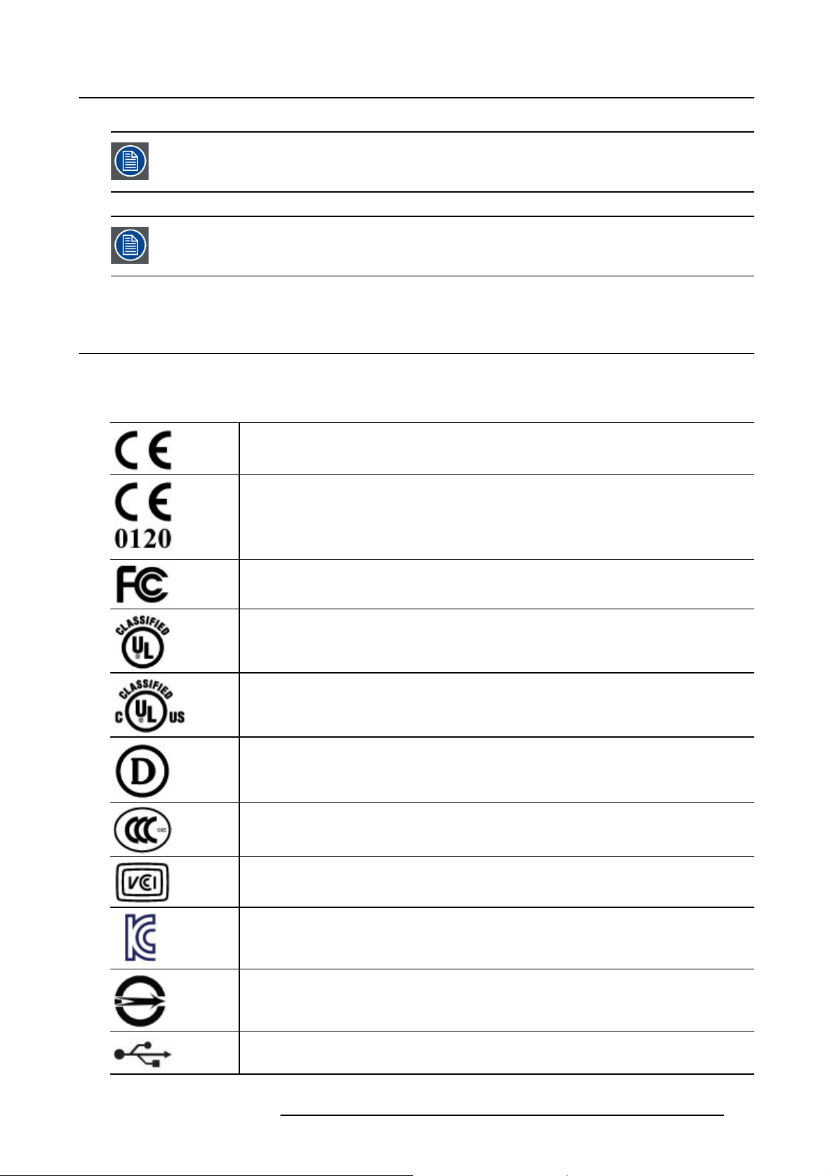
7.5 Exp lanation of symbols
Symbols on the device
On the device or power supply, you may find the following symbols (nonrestrictive list):
Indicates compliance with the Directive 93/42/EEC as Class I device
7. Important information
Indicates compliance with the Directive 93/42/EEC as Class II device
Indicates compliance with Part 15 of the FCC rules (Class A or Class B)
Indicates the device is approved according to the UL regulations
Indicates the device is approved according to the UL regulations for Canada
and US
Indicates the device is approved according to the UL Demko regulations
Indicates the device is approved according to the CCC regulations
Indicates the device is approved according to the VCCI regulations
Indicates the device is approved according to the KC regulations
Indicates the device is approved according to the BSMI regulations
Indicates the USB connectors on the device
K5903500 EONIS 19/09/2014 29
Page 32
7. Important information
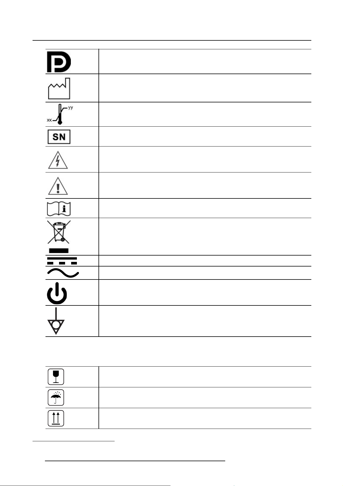
Indicates the DisplayPort connectors on the device
Indicates the manufacturing date
Indicates the temperature limitations6for the device to safely operate within specs
Indicates the device serial no.
Warning: dangerous voltage
Caution
Consult the operating instructions
Indicates this device must not be thrown in the trash but must be recycled,
according to the European WEEE (Waste Electrical and Electronic Equipment)
directive
Indicates Direct Current (DC)
Indicates Alternating Current (AC)
Stand-by
Equipotentiality
Symbols on the box
On the box of the device, you may find the following symbols (nonrestrictive list):
Indicates a device that can
being stored.
Indicates a device that needs to be protected from moisture when being stored.
Indicates the storage direction of the box. The box must be transported, handled
and stored in such a way that the arrows always point upwards.
6. Values for xx and yy can be found in the technical specifications paragraph.
30 K5903500 EONIS 19/09/2014
be broken or damaged if not handled carefully when
Page 33
7. Important information
15
n
20 - 30 Kg
-20 °C
5 %
xx
50 kPa
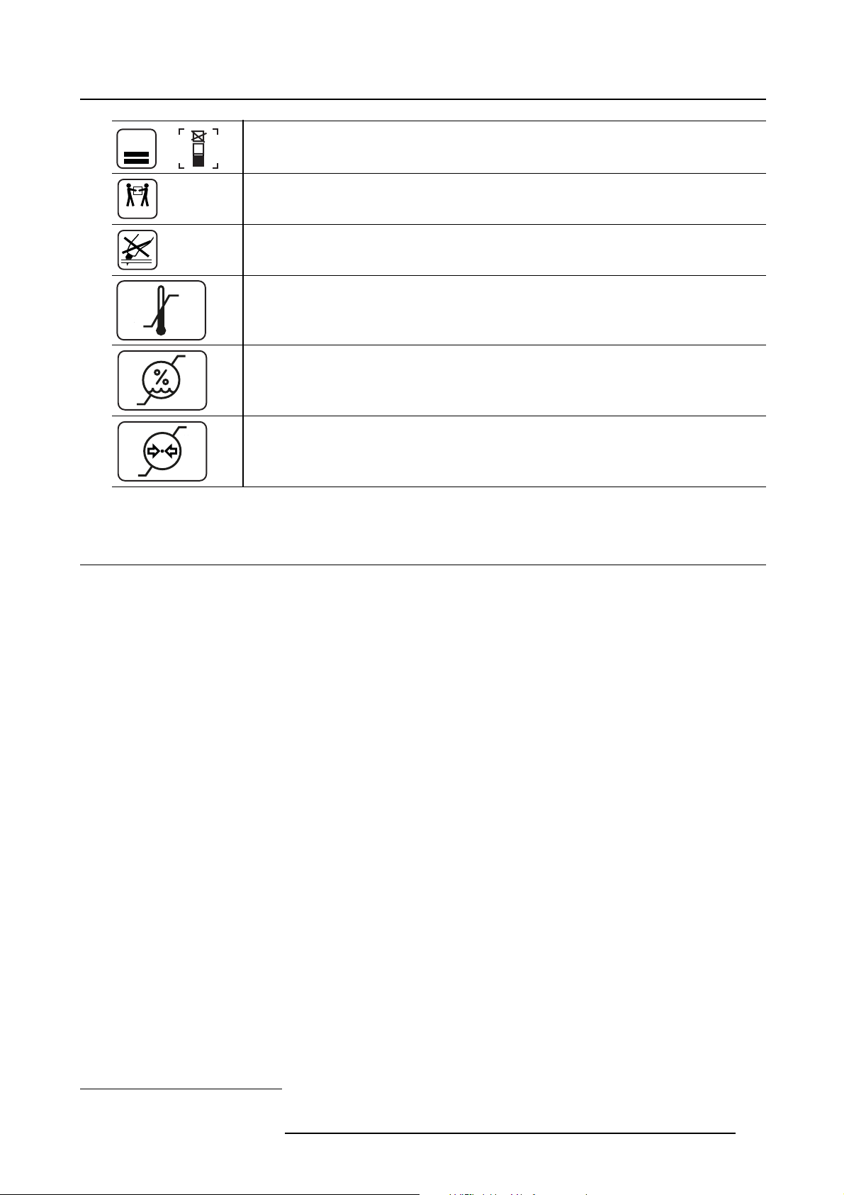
Indicates the maximum number of identical boxes which may be stacked on each
n
other, where “n” is the limiting number.
or
Indicates that the box should be carried with two persons.
Indicates that the box should not be cut with a knife, a cutter or any other sharp
object.
Indicates the temperature limits7to which the device can be safely exposed when
yy
+60 °C
xx
yy
85 %
being stored.
Indicates the range7of humidity to which the device can be safely exposed when
being stored.
x
yyy
106 kPa
Indicates the range7of atmospheric pressure to which the device can be safely
exposed when being stored.
7.6 Legal dis claimer
Disclaimer notice
Although every attempt has been made to achieve technical accuracy in this document, we assume no
responsibility for errors that may be found. Our goal is to provide you with the most accurate and usable
documentation possible; if you discover errors, please let us know.
Barco software products are the property of Barco. They are distributed under copyright by Barco N.V. or
Barco, Inc., for use only under the specific terms of a software license agreement between Barco N.V. or
Barco Inc. and the licensee. No other use, duplication, or disclosure of a Barco software product, in any
form, is authorized.
The specifications of Barco products are subject to change without notice.
Trademarks
All trademarks and registered trademarks are property of their respective owners.
Copyright notice
This document is copyrighted. All rights are reserved. Neither this document, nor any part of it, may
be reproduced or copied in any form or by any means - graphical, electronic, or mechanical including
photocopying, taping or information storage and retrieval systems - without written permission of Barco.
© 2014 Barco N.V. All rights reser
ved.
7. Values for xx and yy can be found in the technical specifications paragraph.
K5903500 EONIS 19/09/2014 31
Page 34

7. Important information
7.7 Technical specifications
Overview
Product acronym
Screen technology TFT Color LCD
Active screen size (diagonal) 541 mm (21.3”)
Active screen size (H x V) 432 mm x 324 mm (17” x 12.76”)
Aspect ratio (H:V)
Resolution
Pixel pitch 0.270
Color imaging
Gray imaging
Color support
Viewing angle (H, V) 178°
MDRC-2221
4:3
2MP (1600 x 1200)
Yes
Yes
10 bit
Ambient Light Compensation
(ALC)
Front sensor Yes
Maximum luminance
DICOM calibrated luminance 250 cd/m²
Contrast ratio
Response time (Tr + Tf)
Housing color
Video input signals DisplayPort, DVI
USB ports
USB standard
Power requirements (nominal)
Power consumption (nominal) 32 W (<1 W in stand-by)
Power save mode Yes
Power management
Dot clock 165 MHz
OSD languages English, French, German, Spanish, Italian, Dutch, Japanese, Tr aditional
Dimensions with stand (W x H
xD)
Dimensions w/o stand (W x H
xD)
Dimensions packaged (W x H
xD)
Net weight with stand 8.7 kg
Net weight w/o stand
Net weight packaged with
stand
Height adjustment range
Tilt
Swivel -45° / +45°
Pivot Yes
Mounting standard
Screen protection N/A
Yes, preset values in OSD
440 cd/m² typical
1500:1 typical
20 ms
Black + Silver
1 upstream, 2 downstream
2.0
100-240 V
DPMS
Chinese, Simplified Chinese, Korean
376 x 591.7 x 201.33 mm (portrait)
376 x 484 x 75.93 mm (portrait)
584 x 667 x 272 mm
5.25 kg
12.4 kg
100.0 +/- 5.0 mm
-5° / +20°
VESA (100 mm)
32 K5903500 EONIS 19/09/2014
Page 35

7. Important information
Certifications CE (MDD 93/42/EEC class I product), CE-2004/108/EC, 2014/30/EU
(Directive 2004/108/EC is repealed with effect from 20 April
2016), IEC 60601-1:2005, ANSI/AAMI ES60601-1 (2005/(R)2012
+ C1:2009/(R)2012 + A2:2010/(R)2012), CAN/CSA-C22.2 No.
60601-1 (2008), DEMKO - EN 60601- 1:2006, EN 60601-1-2:2007,
EN60601-1:2006+A11:2011, KC, VCCI, FCC class B, ICES-001 Level
B, FDA Class I device, RoHS
Supplied accessories
QA software MediCal QAWeb & QAWeb PP
Warranty 3 years
Operating temperature +10°C / +35°C
Storage & transport
temperature
Operating humidity 20% - 85% (non-condensing)
Storage & transport humidity 5% - 95% (non-condensing)
User Guide
Cable routing strap
Video cables (1 x DVI + 1 x DP)
Main cables (UK, European (CEBEC/KEMA) or USA (UL/ CSA; adaptor
plug NEMA 5-15P))
USB 2.0 cable
Cleaning cloth
This adapter(s) is a forming part of the medical device.
(Manufacturer: BridgePower Corp., BPM060S24F09; Input: 100-240 V
AC, 50-60 Hz, 1.5 A; Output: +24V DC (
-20°C / +60°C
), 2.7 A)
Operation altitude
Storage & transport altitude
Operating pressure
Storage & transport pressure
3000 m
5500 m
70 kPa - 106 kPa
50 kPa - 106 kPa
K5903500 EONIS 19/09/2014 33
Page 36

7. Important information
34 K5903500 EONIS 19/09/2014
Page 37

A. Troubleshooting
A. TROUBLESHOOTING
A.1 Troubl esho ot ing
General
If you experience trouble with the LCD display, refer to the following troubleshooting. If the problem persists, please contact your local dealer or our service center.
Problem: No image appears on the screen
• Push the standby button.
• Check if all I/O and power connectors are correctly connected as described in the “installation” section.
• Make sure the pins of the connectors are not crooked or broken.
Problem: Partial image or incorrectly displayed image
• Check to see if the resolution of your computer is higher than the resolution of the display.
•Re-configure the resolution of your computer to make it less than or equal to the native resolution
(1600 x 1200)
A.2 Warning signals
General
Sometimes you may see warning messages for this display. This means that the display cannot correctly
receive the signal form the computer graphics card.
Problem: No signal
This message means that the display has been powered on but it cannot receive any signal from the
computer graphics card. Check all the power switches,
Problem: Out of range
This message means that the signal of the computer graphics card is not compatible with the display.
When the signal is not included in the compatibility mode we have listed in the appendices of this manual,
the display will show this message.
power cables, and video cable.
K5903500 EONIS 19/09/2014
35
 Loading...