


UTILITY SYSTEMS
Generator Condition Monitor (GCM-X)
Installation and Operation Manual
GA0353P02 Rev. B

Contents
Specifications....................................................................................................................................... 5
Application .......................................................................................................................................... 6
Principle of Operation .................................................................................................................... 6
System Description ............................................................................................................................. 7
System Electronics .......................................................................................................................... 7
Display Panel ................................................................................................................................. 7
Input/Output Board......................................................................................................................... 7
Installation........................................................................................................................................... 8
Mounting......................................................................................................................................... 8
System Design Considerations ........................................................................................................... 9
Transit Time Calculations................................................................................................................ 10
Sampling System Components ........................................................................................................ 11
Electrical Connections ...................................................................................................................... 12
Contacts ........................................................................................................................................ 12
Signals .......................................................................................................................................... 12
System Operation ............................................................................................................................. 13
GCM-A Initial Startup .................................................................................................................. 13
Typical Responses to GCM-A Warning & Alarm Indications ..................................................... 14
GCM-A Initialization ....................................................................................................................... 16
GCM-A Menu Displays .................................................................................................................... 17
Navigating the LCD Display ........................................................................................................ 17
LCD Display Menu — Two Modes of Operation ......................................................................... 17
Menu Profile ................................................................................................................................. 17
Menu Navigation Tutorial................................................................................................................ 18
Activating the Menu ...................................................................................................................... 18
Navigating the Menu in Scrolling Mode (GCM-A default) .......................................................... 18
Disabling Scrolling Mode............................................................................................................. 18
Navigating the Menu in Non-Scrolling Mode............................................................................... 18
Function (FN) Menu ..................................................................................................................... 19
Setup Menu ................................................................................................................................... 19
Test Menu ...................................................................................................................................... 20
View Menu .................................................................................................................................... 21
1
GA0383P02 Rev. C

Log Menu ...................................................................................................................................... 22
Procedures ......................................................................................................................................... 23
Draining the Humidifier ............................................................................................................... 23
Adjusting the Ambient Airflow...................................................................................................... 23
Adjusting the Generator Airflow .................................................................................................. 24
Adjusting the Cloud Chamber Airflow ......................................................................................... 25
Setting the Ambient Gain .............................................................................................................. 25
Setting the Ambient Warning Level...............................................................................................25
Setting the Ambient Alarm Level .................................................................................................. 25
Setting the Generator Gain .......................................................................................................... 26
Setting the Generator Warning Level ........................................................................................... 26
Setting the Generator Alarm Level ...............................................................................................26
Setting the Differential Warning Level ......................................................................................... 26
Setting the Differential Alarm Level ............................................................................................. 27
About the Faults Log .................................................................................................................... 27
About the Power Log .................................................................................................................... 28
Modes of Operation .......................................................................................................................... 29
Startup .......................................................................................................................................... 29
Startup Problems .......................................................................................................................... 29
Alternating Operation .................................................................................................................. 30
Ambient Only Operation ............................................................................................................... 30
Generator Only Operation ........................................................................................................... 31
Troubleshooting ................................................................................................................................ 32
Remote Access ................................................................................................................................... 34
Requirements ................................................................................................................................ 34
GCM-A Modem Installation ......................................................................................................... 34
Using a Custom Modem String.....................................................................................................34
Changing the Modem String ......................................................................................................... 35
Establishing a Direct Connection................................................................................................. 35
Establishing a Dialup Connection................................................................................................36
Viewing Output History ................................................................................................................ 36
Configuring the GCM-A for Historical Data Collection ............................................................. 36
Maintenance ...................................................................................................................................... 38
Periodic Maintenance................................................................................................................... 38
Daily ............................................................................................................................................. 38
Weekly ........................................................................................................................................... 38
Monthly ......................................................................................................................................... 38
Quarterly ...................................................................................................................................... 38
Annually ........................................................................................................................................ 38
GA0383P02 Rev. C
2

Figures
Figure 1 - System Overview .............................................................................................................................. 39
Figure 2 - GCM-A Outline ................................................................................................................................ 40
Figure 3 - GCM-A Mounting ............................................................................................................................ 41
Figure 4 - Customer Interface Wiring ............................................................................................................... 42
Figure 5 - Closed Circuit “H” Probe ................................................................................................................. 43
Figure 6 - Closed Circuit “U” Probe ................................................................................................................. 44
Figure 7 - Open Circuit “Sample Heads” .......................................................................................................... 45
Figure 8 - Open Circuit “Probes” ...................................................................................................................... 46
Figure 9 - Sampling System, 3/8” Typical (PVC) ............................................................................................. 47
Figure 10 - Sampling system, 1/2” Typical (PVC) ............................................................................................ 48
Figure 11 - Sampling System, 1/2” Flange Configuration ................................................................................ 49
Figure 12 - Zone Manifold ................................................................................................................................ 50
Figure 13 - Sample Head ................................................................................................................................... 51
Figure 14 - Sample Probe .................................................................................................................................. 52
Figure 15 - Zone Manifold Flow, DP mm Water............................................................................................... 53
Figure 16 - Particle Concentration .................................................................................................................... 54
Figure 17 - Control Panel Detail ....................................................................................................................... 55
Figure 18 - Manifold DP Gage .......................................................................................................................... 56
3
GA0383P02 Rev. C

GENERATOR CONDITION MONITOR (GCM-A)
IMPORTANT INFORMATION
THIS EQUIPMENT OPERATES AT VOLTAGE LEVELS THAT CAN BE HAZARDOUS TO
PERSONNEL. THE SECTION ABOUT SAFETY CONSIDERATIONS SHOULD BE READ
BEFORE INSTALLING OR SERVICING.
THESE INSTRUCTIONS DO NOT PURPORT TO COVER ALL DETAILS OR VARIATIONS
IN EQUIPMENT NOR TO PROVIDE FOR EVERY POSSIBLE CONTINGENCY TO BE
MET IN CONNECTION WITH INSTALLATION, OPERATION OR MAINTENANCE.
SHOULD FURTHER INFORMATION BE DESIRED, OR SHOULD PARTICULAR
PROBLEMS ARISE THAT ARE NOT COVERED SUFFICIENTLY FOR THE
PURCHASER’S PURPOSES, THE MATTER SHOULD BE REFERRED TO
ENVIRONMENT ONE CORPORATION AT +1 518 346 6161 OR WWW.EONE.COM/
DETECTION.
SITE MANAGEMENT IS RESPONSIBLE FOR ASSURING THAT ALL PERSONNEL
WORKING WITH THIS SYSTEM ARE ADEQUATELY TRAINED IN SAFETY
CONSIDERATIONS AND THAT THEY HAVE RECEIVED THE NECESSARY TRAINING TO
PROPERLY OPERATE THE EQUIPMENT.
GENERATOR CONDITION MONITOR (GCM-A)
SAFETY CONSIDERATION
THE SYSTEM ELECTRONICS ENCLOSURE CONTAINS 115 AND/OR 230 VOLTS AC.
THIS VOLTAGE APPEARS AT THE AC POWER STRIP AND VARIOUS OTHER POINTS.
ALL ELECTRICAL CONNECTIONS TO THE SYSTEM ELECTRONICS SHOULD BE
TESTED AND VERIFIED TO BE CORRECT.
ALL WIRING MUST BE IN ACCORDANCE WITH LOCAL CODES AND PROFESSIONAL
PRACTICE.
USE OF THIS EQUIPMENT IN A MANNER NOT SPECIFIED BY ENVIRONMENT ONE
CORPORATION IS STRICTLY PROHIBITED.
GA0383P02 Rev. C
4

Specifications
Measurement Characteristics
Detection principle Submicron particle detector
Air Flow Rate Adjusted by Zone Manifold, nominal 14 LPM
Readout (bar graph) Ambient Air 0% to 100% of scale
Electrical Characteristics
Power Input, grounded power cable 115/230 VAC, 50/60 Hz
Output Relays, general purpose
Ambient Alarm, Generator Alarm,
Differential Alarm, Common Warning,
System Trouble, Flow Trouble 120 VAC/28VDC / 3.0 A
Output Signal (4-20 mA)
Generator Air 0% to 100% of scale
Ambient Air 0% to 100% of scale
Generator Air 0% to 100% of scale
Mechanical Characteristics
Dimensions, overall 24” H x 22” W x 9 1/8” D*
(610 mm x 559 mm x 232** mm)
Weight, approximate 88 lbs. (40 kg)
Connectors, gas inlet 3/8” NPT, female
Temperature, maximum 32-122 F (0-50 C)
Area Classification CE, Non Hazardous
Relative Humidity 0-95%
Controls 5-key membrane switch keypad with liquid
crystal display
* 8”/203 mm for GD0080G02
** 10”/254 mm for GD0080G01
5
GA0383P02 Rev. C

Application
The Generator Condition Monitor for air-cooled machines (GCM-A) is a sensitive real-time
instrument designed to provide early warning indication of overheating (or arcing) in aircooled generators before extensive damage can occur. Tests conducted on operating aircooled generators have shown that the GCM-A can detect thermal decomposition of small
amounts of insulating materials.
Thermal decomposition of organic materials such as epoxy paint, core lamination enamel or
other insulating materials used in the generator results in the production of a large number
of small particles. The onset of particle production, as the material is heated, occurs at a
temperature characteristic of the material (thermal particulation point) and its surrounding
atmosphere. Below this temperature, no particles are created, yet once the critical
temperature is reached (thermal particulation point – TPP), millions of submicron particles
are generated each second for every square centimeter of surface area.
The GCM-A features:
· Microprocessor-based electronics
· Self-diagnostics
· Output indication
· Trouble indication
· Allowance for remote control/display and communication
Principle of Operation
A basic understanding of the GCM-A is necessary to properly utilize the information that the
instrument provides.
Particle detection is by means of a detector utilizing the condensation nuclei principle (cloud
chamber).
In operation, an air sample is delivered to the detector by means of a centrifugal blower
connected to two sets of sampling lines; one line is dedicated to the ambient air and the
second is dedicated to the generator’s cooling circuit. A portion of these air samples is first
diverted into a humidifier and humidified to approximately 100% relative humidity, then
directed to the cloud chamber where it is subjected to a rapid vacuum expansion. The effect
of the vacuum is to cool the air sample and cause water droplets to condense onto particles
that may be present in the air sample.
It is known that particles smaller than the wavelength of visible light occur spontaneously as
material is heated, and in numbers far above those present in a normal ambient
environment. As a result, thermally generated particles cause many droplets to form a cloud
which is then detected by the optical system of the cloud chamber.
GA0383P02 Rev. C
6

System Description
The GCM-A is primarily designed for use on air-cooled generators, although application to
other air-cooled machines is possible. Its main purpose is to provide early warning and
detection of overheating (or arcing) in these machines.
The major components of the GCM-A are the System Electronics and the sampling system.
System Electronics
The System Electronics consist of one display board, one controller board, one input/output
board, two airflow metering boards, one power supply, one vacuum pump, one cloud
chamber, one blower fan and one sampling manifold.
The System Electronics provide calibration, mode selection, alarm contacts, data logging,
system inputs/outputs and diagnostics.
Fail-safe operation of the GCM-A is assured by:
• On power-up the GCM-A must execute and pass qualifying self tests. Failure in any test
results in the suspension of operation and the annunciation of the condition causing the
failure.
• Following power-up and/or system reset, the GCM-A is continuously supervised by an
independent watchdog monitor that serves to reset it should its operation become
erratic.
• The GCM-A is completely self-supervised and continuously checks itself for legal
processor functioning, proper vacuum levels, internal voltages, communication accuracy,
integrity of cabling and relay operation. Any faults are immediately annunciated.
Display Panel
The Control/Display Panel provides control of all functions of the GCM-A as well as
complete annunciation of GCM-A’s status (Figure 17). Functions are accessed by means of
a four-button membrane-switch keypad and 20-character Liquid Crystal Display (LCD).
Generally, pressing the Fn (Function) key causes the LCD to continuously scroll the names
of the available functions. A function may then be accessed by pressing the Enter key when
the function name appears. See “GCM-A Menu Displays” for more information.
The Display Panel provides Light Emitting Diodes (LED’s) to annunciate GCM-A status; they
indicate Warning, Alarm and Trouble conditions. A green LED indicates AC Power.
Since all configuration constants are stored in non-volatile memory, these values will not be
lost should the system be initialized, or should it lose, then regain, AC power.
Input/Output Board
The Input/Output board assembly has terminal strips where all customer connections to the
relay and signal outputs are made. Wire access is provided by the three knockouts at the
top and/or bottom of the Enclosure.
7
GA0383P02 Rev. C

Installation
These instructions provide details to facilitate the equipment installation.
Mounting
The GCM-A (GD0080G01) should be installed indoors. If outdoor installation is necessary, a
protective enclosure should be considered and discussed with Environment One. Locate the
GCM-A out of direct sunlight to prevent the interior ambient temperature from exceeding
50 C (122 F). If a protective enclosure is used, it should also be ventilated.
A GCM-A may be supplied with a protective enclosure. Installation of this variation
(GD0080G02) system begins with installation of the exterior enclosure. This enclosure
should be mounted in accordance with Figure 3.
Please note that both the exterior enclosure and the GCM-A cabinet should be securely
attached to the mounting surface. Securing the GCM-A cabinet only to the exterior
enclosure is not recommended.
GA0383P02 Rev. C
8

System Design Considerations
The GCM-A system consists of the detector unit (the GCM-A itself) and an associated air
sampling system. When designing a system for a particular application, one needs to
consider:
a) The configuration of the generator’s cooling system. In particular, it is important to
know whether the application is a single pass (open) or enclosed (closed) cooling circuit.
This will play a major role in the sampling system design layout. A cooling system
schematic and sectional views of the generator are valuable to this process and should
be provided to Environment One.
b) The mounting location of the GCM-A cabinet. The particular location of the GCM-A
cabinet will play a role in the sampling system design layout and electrical connections
and will also assist in identifying key mechanical installation considerations. For
example, if the GCM-A is to be mounted near or on the generator’s exterior case, the
generator OEM may need to be contacted for information, approval and/or instruction.
Consideration of these and other mechanical factors will facilitate installation.
c) The distance between the GCM-A cabinet and the farthest point the sampling
system will reach. This information is key to the transit time analysis of the sampling
system. Identification of physical obstacles and/or considerations that will impact the
specific piping layout will also be considered. Often, the cooling system schematic
referred to above will provide much of the information sought.
d) The preferred piping material to be used in the sampling system. The GCM-A’s
sampling system can employ a variety of pipe sizes and types. Environment One does
not supply the sampling system’s pipe, but will be interested in learning whether the
power plant has a preference for a particular material – for example, a plant may have a
supply of 1/2-inch conduit left over from electrical service installations throughout the
plant; this material could be viewed as the preferred sampling system pipe. Environment
One will ask the plant whether there is a preference in this regard. Typically, 3/8-inch
NPT is used in a GCM-A sampling system.
9
GA0383P02 Rev. C

Transit Time Calculations
Environment One will utilize information from the customer to develop a sampling system
transit time calculation. The main purpose for this analysis is to verify that the sampling
system will meet minimum system requirements for air flow through the sampling system
and to establish an expectation for the amount of time an overheat signal generated from
within the generator will take to reach the detector unit.
During a typical GCM-A system start-up and commissioning, a 100-watt resistor will be
overheated within the cooling circuit. When this is done, the transit time analysis will be
validated, as there should be a rough correlation between the transit time design
expectation and the actual interval between the resistor being overheated and a response
by the GCM-A.
Should the approximated transit time not be validated during the commissioning of the
system, air flow through the Zone Manifolds would be validated using an external DP gage
to verify proper flow rates and adjustments to flow would be made to meet system
requirements and customer expectations.
GA0383P02 Rev. C
10

Sampling System Components
As noted, the GCM-A’s sampling system is composed of a pipe network that delivers an air
sample to the GCM-A. The individual components of a GCM-A sampling system may differ
from installation to installation (see isometric views Figures 5 though 8 of an open and
closed circuit application). In most instances, the following components are used (see
Figures 9 through 14 for component details):
• Zone Manifold – Two Zone Manifolds are used in the GCM-A system; one for the
Ambient signal, the other for the Generator signal. These components are typically
installed close to the GCM-A and are used to adjust airflow from each segment of the
sampling system network. Each Zone Manifold will be supplied with pipe unions to ease
removal of these components from the sampling system should the need arise.
Communication between Environment One and the power plant customer will confirm
the particular configuration of the pipe unions. A Zone Manifold also contains a
replaceable filter that helps guard against dirt and insects from entering the inlet manifold
of the GCM-A system (possibly obstructing flow).
• Sampling pipe — This material is supplied by the site. Communication between
Environment One and the power plant customer will determine necessary lengths. It is
the responsibility of site management to assure that sampling system piping is installed
in accordance with sampling system design parameters, local codes and professional
practice.
• Sample Heads — Sample Heads may be used as part of the sampling system, and
particularly for the Ambient signal. Sample Heads have a fixed orifice and contain a
replaceable filter that helps guard against dirt and insects from entering the sampling
system (possibly obstructing flow); see Figure 13.
• Sample Probes — Sample Probes are sections of sampling system pipe that have
holes drilled in them at particular spacing and with particular diameters. They are used as
an alternative to Sample Heads and are often preferred for the Generator signal portion of
the sampling system because of their inherent flexibility. Communication between
Environment One and the power plant customer will determine whether Sample Probes
will be used in a GCM-A sampling system; see Figure 14.
• DP Gage — The DP Gage is an external metering component used to confirm the air
flow across a Zone Manifold. The default GCM-A system design parameter for air flow is
14 LPM for each sample line. The DP Gage will be utilized during system commissioning
and at maintenance intervals to validate sampling system operation; see Figure 18.
11
GA0383P02 Rev. C

Electrical Connections
Electrical connections are made through three knockouts provided at the top and bottom of
the GCM-A cabinet (Figure 4). The system power requirement is 115/230 VAC (+/- 10%),
50/60 Hz. The source of AC power should be reliable and not subject to severe transients.
Wiring and wire routing should be in accordance with Figure 4 so that noise generated from
the AC power and contacts does not interfere with the signals. If a circuit breaker is used, it
should be 10 amps. The ground wire should be 12 AWG with 25-amp capacity.
ALL WIRING MUST BE IN ACCORDANCE WITH LOCAL CODES AND PROFESSIONAL
PRACTICE.
Contacts
As shown in Figure 4, the GCM-A provides these relay contacts:
· Ambient Alarm Relay. Both a normally open and a normally closed contact (single pole,
double throw configuration) is provided and an alarm is signaled by an energized relay.
· Generator Alarm Relay. Both a normally open and a normally closed contact (single
pole, double throw configuration) is provided and an alarm is signaled by an energized
relay.
· Differential Alarm Relay. Both a normally open and a normally closed contact (single
pole, double throw configuration) is provided and an alarm is signaled by an energized
relay.
· Warning Relay. Both a normally open and a normally closed contact (single pole,
double throw configuration) is provided and a warning is signaled by an energized relay.
· Flow Trouble Relay. Both a normally open and a normally closed contact (single pole,
double throw configuration) is provided a flow rate problem is signaled by an energized
relay.
· System Trouble Relay. Both a normally open and a normally closed contact (single
pole, double throw configuration) is provided, and Trouble is signaled by a de-energized
relay.
Signals
· Ambient Output Level Signal. 4 to 20 mA signal (transmitter)
· Generator Output Level Signal. 4 to 20 mA signal (transmitter)
GA0383P02 Rev. C
12

System Operation
GCM-A Initial Startup
The GCM-A leaves the factory without any water in the water bottle or in the humidifier to
prevent damage during shipping. Before starting the GCM-A, fill the water bottle with
distilled water. (WARNING: The use of anything other than distilled water will damage
the GCM-A and will void the warranty.)
To fill the GCM-A water bottle:
• Open the outer door.
• Remove the six screws from the GCM-A subdoor.
• Remove the water bottle from the water bottle shelf.
• Remove the cap from the water bottle and fill it with distilled water.
• Secure the cap on the water bottle and return the bottle to the water bottle shelf.
• Secure the GCM-A subdoor and outer door.
The humidifier is filled during the boot process (see the section GCM-A Initialization for
details of the boot process). At the point in the boot process where the GCM-A normally
indicates “WATER OK,” it will instead indicate “WATER=0”. After one second, “WATER=0”
will be followed by “WATER=1,” and so on until “WATER=15” is reached. At this point the
GCM-A will flash the prompt “CONTINUE FILLING?”. Press the enter key to continue filling.
The humidifier will be filled to capacity at or about “WATER=17”.
The GCM-A may detect that the Zone Manifolds need to be adjusted during the initial boot.
If it detects that the flow rates are out of specification, it will stop the boot process and flash
the out of specification reading on the display. It will flash “AMB FLO = N.N LPM” if the
ambient air flow rate is out of specification and/or “GEN FLO = N.N LPM” if the generator
airflow rate is out of specification. Adjust the appropriate Zone Manifold to a nominal 14 LPM
correct the problem and validate the air flow through the Zone Manifold using the DP Gage.
The two zone manifolds are adjusted with an allen head set screw located on their lower
right hand side (see Figure 12). Turn the set screw in a clockwise direction to decrease the
airflow or in a counterclockwise direction to increase the airflow. The GCM-A requires
that the airflow be between 7 and 21 LPM (nominal 14 liters per minute) for initial startup.
After the GCM-A has started successfully, adjust the airflow and clear the event logs.
You may want to run the tutorial called “Menu Navigation Tutorial” to familiarize yourself with
menu navigation before proceeding with these steps.
See the procedures titled “Adjusting the Ambient Airflow” and “Adjusting the Generator
Airflow” to adjust the airflow. See the sections “CLEAR FAULTS LOG” and “CLEAR POWER
LOG” under the heading “Log Menu” to clear the event logs.
13
GA0383P02 Rev. C

Typical Responses to GCM-A Warning & Alarm Indications
This section addresses what a power plant may consider as reasonable actions in response
to particular GCM-A indications. It does not purport to cover all instances.
The GCM-A provides information for plant personnel to use in making operational decisions.
The information provided is often validated by other I&CS. Plant management is encouraged
to consider the relationship of the GCM-A to other systems installed on site. By considering
these relationships, plant management will be in the best position to maximize the utility of
the GCM-A to the plant’s efficient operation.
In the event of:
GCM-A System Trouble — Select SHOW FAULTS LOG from the <LOG MENU>. If no
faults are indicated, then the operator may have disabled monitoring. If faults are indicated,
see the section “About the Faults Log” for interpretation.
Ambient Warning and Alarm — The Warning point is typically selected based on an initial
examination of the normal, or typical, background particle level at the site. Standard practice
is to allow a GCM-A run for several days to determine the highest nominal background
particle level at the site and then select a Warning point that is marginally above that. The
Alarm set point is similarly arrived at; the Alarm point must always higher than the Warning.
When Ambient particle levels rise above the Warning and possibly to the Alarm threshold, it
is reasonable to ask whether this is a short-term condition or whether the nominal
background particle level has changed due to the introduction of another environmental
factor.
In the event of an Ambient Warning or Alarm, examine the operating environment for the
presence of particle generation sources that are not common to the normal operating
environment (excessive exhaust or a fire is a good example of an extraneous source). If
there is such a temporary extraneous event, site personnel should consider whether it
can/should be eliminated/anticipated in the future and make adjustments to Warning and
“Alarm” set points as necessary.
If additional equipment has been installed at the plant site since the GCM-A’s installation
date, an Ambient Warning or Alarm may result from that equipment’s impact on nominal
background particle levels. In such an instance, site personnel may need to consider
increasing the Warning point to a level that is above the highest anticipated nominal particle
level. Essentially, the GCM-A is an environmental monitor; therefore, if the nominal
background particle level has changed because of the introduction of a sustained particle
generating source, reassessment of Warning and Alarm points is required.
Generator Warning and Alarm — The Generator Warning and Alarm points are selected
similarly to the Ambient points (see above). Therefore, a change in the nominal Ambient
particle level could be expected to cause a similar particle level increase in the Generator
signal, insofar as the Ambient air represents the same air as the air contained within the
generator’s cooling circuit.
If a Generator Warning or Alarm occurs and it is not accompanied by an Ambient Warning
or Alarm, site personnel are advised to consider that overheating may be occurring within
GA0383P02 Rev. C
14

(Typical Responses, cont’d)
the generator cooling circuit. In this instance, other site instrumentation should be reviewed
for corroborating indications of generator overheating.
Differential Warning and Alarm — A Differential Warning or Alarm occurs as a result of a
difference existing between Ambient and Generator particle levels. It is an expression of
“Generator less Ambient” and its value cannot equal less than zero.
The Differential Warning and Alarm set points are adjustable, with the factor default being a
30 percent difference for Warning and a 50 percent difference for Alarm. These settings are
adjustable.
In the event of a Differential Warning or Alarm, other site instrumentation should be
reviewed for corroborating indications of generator overheating. The GCM-A’s indication of a
Differential Warning, and particularly a Differential Alarm, is the most serious indication of a
thermal particulation event occurring within the generator’s cooling circuit. Site personnel
are advised to immediately initiate internal procedures for dealing with an acute problem that
could lead to generator failure.
Environment One is sometimes asked whether a GCM-A Differential Alarm should be used
to “trip” a generator off-line. This is not a question that Environment One is in a position to
respond to, as decisions relating to taking a generator off-line involve significant economic
considerations/repercussions and are solely the responsibility of site management.
Environment One can only advise GCM-A end-users that our experience has been that
operators typically reduce load upon a verified alarm in one of our overheat monitoring
instruments. They typically evaluate whether a reduced load changes the alarm condition
and then act in accordance with their established internal procedures. In the event that plant
operators choose to use a GCM-A to trip a generator, the “Differential Alarm” is the only
indication that should be used.
15
GA0383P02 Rev. C

GCM-A Initialization
Apply system power to the GCM-A. The GCM-A DISPLAY PANEL will respond with (a) all
discrete LED’s lit; (b) all segments of the AMBIENT and GENERATOR bar graphs lit; and (c)
all pixels of the LCD display on.
After a delay of two seconds, (a) all discrete LED’s, except the AC POWER, SYSTEM
TROUBLE and FLOW LED’s, will turn off; (b) all segments of the AMBIENT and
GENERATOR displays will turn off; and (c) the display will echo the results of cold start
initialization:
· “GCM-A Ver 1.7B-8”
· “CHECKSUM OK”
· “POWER OK”
· “RELAY TEST …”
· “… PASSED”
· “STARTING …” will flash for two seconds;
· “ROTARY VALVE …”
· “… PASSED”
· “VACUUM OK”
· “SAMPLE LINE ...”
· “… PASSED”
· “GEN SOLENOID ...”
· “… PASSED”
· “AMB SOLENOID ...”
· “… PASSED”
· “AMB FLO=14.0 LPM”
· “GEN FLO=14.0 LPM”
· “WATER OK”
· “END DIAGNOSTICS”
“NORMAL OPERATION” will flash for two seconds; the GCM-A will begin normal operation
and the display will read “GCM-A by E/One.”
GA0383P02 Rev. C
16

GCM-A Menu Displays
The following sections provide definitions and user information regarding the various menus
that are accessible via the GCM-A’s LCD display. It is strongly recommended that users
familiarize themselves with this section. Additional questions can be forwarded to
Environment One at +1 518 346-6161 or www.eone.com/detection.
Navigating the LCD Display
Four keys are used to control menu operation. The keys are FN, ENTER, UP ARROW and
DOWN ARROW.
· The FN key activates the menu and exits the menu.
· The ENTER key selects an item from the menu.
The UP ARROW and DOWN ARROW keys change the selection displayed.
LCD Display Menu — Two Modes of Operation
The menu has two modes of operation. The modes are scrolling and non-scrolling.
· In scrolling mode the selection shown on the LCD changes automatically every two
seconds.
· In non-scrolling mode the UP ARROW and DOWN ARROW keys must be used to
change the selection.
Scrolling is the default mode. Users can change modes by reviewing the SETUP MENU
section in the following pages.
Menu Profile
Five menus are available: the Function menu, the Log menu, the Setup menu, the View
menu and the Test menu. The Function menu is the top-level menu; all of the other menus
are accessed through this menu.
Function
· Log
· Setup
· View
· Test
17
GA0383P02 Rev. C

Menu Navigation Tutorial
Activating the Menu
Press FN to start the menu. The LCD should display the prompt <FUNCTION MENU>.
Press FN again to turn it off.
Navigating the Menu in Scrolling Mode (GCM-A default)
1. Press FN to start the menu. The LCD should display the prompt <FUNCTION MENU>.
After two seconds the prompt should change to GO REMOTE.
2. Wait until the prompt GO TO VIEW MENU and press the ENTER key. The LCD should
display the prompt <VIEW MENU>.
3. Wait until the prompt VIEW LEVEL and press the ENTER key. The display should show
GENERATOR=N.N% (or AMBIENT=N.N%) where N.N is the present value of the cloud
chamber response. Press the FN key; the prompt will be restored to VIEW LEVEL.
4. Press FN again. The prompt will be restored to GO TO VIEW MENU.
5. Press FN a third time. The LCD will display “GCM-A by E/One” as the menu is
deactivated.
Disabling Scrolling Mode
1. Press FN to start the menu.
2. Wait until the prompt GO TO SETUP MENU and press ENTER.
3. Wait until the prompt SET SCROLL OFF and press ENTER.
4. The prompt will flash SET SCROLL OFF.
5. Press FN to return to the beginning of the menu.
Navigating the Menu in Non-Scrolling Mode
1. The LCD should display the prompt <FUNCTION MENU>. Press the DOWN ARROW
key until the prompt GO TO VIEW MENU and press the ENTER key.
2. The LCD should display the prompt <VIEW MENU>. Press the DOWN ARROW key until
the prompt VIEW LEVEL and press the ENTER key. The display should read
GENERATOR=N.N% (or AMBIENT=N.N%) where N.N is the present value of the cloud
chamber response.
3. Press the FN key. The prompt will be restored to VIEW LEVEL.
4. Press FN again. The prompt will be restored to GO TO VIEW MENU.
5. Press FN a third time. The LCD will display “GCM-A by E/One.”
GA0383P02 Rev. C
18

Function (FN) Menu
· GO REMOTE Select this item to transfer control to an active remote control software
session. The GO REMOTE prompt will flash for two seconds after it is selected. If the
FN key is pressed while GO REMOTE is still flashing, transfer will be canceled. If the
GCM-A cannot detect an active remote control software session, the transfer will be
canceled and the GCM-A will remain in local mode.
· GO LOCAL Select this item to transfer control to the display panel located on the front
of the GCM-A cabinet (only shown if control was previously transferred to an active
GCM-A Remote Control Software session). The GO LOCAL prompt will flash for two
seconds after it is selected. If the FN key is pressed while GO LOCAL is still flashing,
transfer will be canceled.
· GO TO LOG MENU Select this item to enter the LOG MENU. The log menu contains
selections to view and clear the fault and power logs. The log menu also includes a
selection to view the software version number.
· GO TO SETUP MENU Select this item to enter the SETUP MENU. The setup menu
includes selections for setup and configuration.
· GO TO TEST MENU Select this item to enter the TEST MENU. The test menu contains
selections to test the power supplies, the keypad, the relays, the vacuum pump, the
cloud chamber, the bar graphs and the four- to 20-milliamp (4-20 mA) outputs.
· GO TO VIEW MENU Select this item to enter the VIEW MENU. The view menu contains
selections to view the water usage, the LED current, the cloud chamber output, the
vacuum, the air flow and the cloud chamber period.
Setup Menu
· AMBIENT GAIN Select this item to change the ambient gain. See Setting the Ambient
Gain for more information.
· GENERATOR GAIN Select this item to change the generator gain. See Setting the
Generator Gain for more information.
· AMBIENT FLOW ADJ Select this item to change the ambient flow limits. See Adjusting
the Ambient Airflow for more information.
· GENERATOR FLOW ADJ Select this item to change the generator flow limits. See
Adjusting the Generator Airflow for more information.
· AMBIENT WARN Select this item to change the ambient warning level. See Setting the
Ambient Warning Level for more information.
· GENERATOR WARN Select this item to change the generator warning level. See
Setting the Generator Warning Level for more information.
· DIFFERENCE WARN Select this item to change the difference warning level. See
Setting the Difference Warning Level for more information.
19
GA0383P02 Rev. C

(Setup Menu, cont’d)
· AMBIENT ALARM Select this item to change the ambient alarm level. See Setting the
Ambient Alarm Level for more information.
· GENERATOR ALARM Select this item to change the generator alarm level. See Setting
the Generator Alarm Level for more information.
· DIFFERENCE ALARM Select this item to change the difference alarm level. See Setting
the Difference Alarm Level for more information.
· DRAIN WATER This item is to be used for decommissioning the instrument. Select this
item to drain the humidifier. See Draining the Humidifier for more information.
· CHAMBER FLOW ADJ Select this item to adjust the chamber airflow. See Adjusting
Chamber Airflow for more information.
· MONITORING MODE This item is to be used for troubleshooting. When selected, the
GCM-A will display its operation mode. The GCM-A can operate in one of four modes:
Normal Operation, Alternating Operation, Ambient Only and Generator Only. Use the
arrow keys to scroll through the choices and press the ENTER key to select one. See
Normal Operation, Alternating Operation, Ambient Only Operation or Generator Only
Operation for more information.
· START MONITORING This item is displayed when the monitoring is currently turned off.
Select it to turn monitoring on. When selected, the START MONITORING prompt will
flash STARTING for two seconds before monitoring begins. If the FN key is pressed
while it is still flashing, the command will be canceled. See Normal Operation for more
information.
· SET SCROLL OFF This item is displayed when the scrolling is currently turned on.
Select it to turn scrolling off. When scrolling is inactive, the displayed menu items will not
change until a menu key (UP ARROW, DOWN ARROW, FN or ENTER) is pressed.
· SET SCROLL ON This item is displayed when the scrolling is currently turned off. Select
it to turn scrolling on. When scrolling is active, the displayed menu items will change
once every two seconds.
Test Menu
· CONTACT TEST Select this item to start an interactive test of the relay contacts. The
GCM-A will place all relays except one in a de-energized condition. The LCD will display
the name of the single relay that is still energized. Use the arrow keys to change which
relay is energized. Press the FN or ENTER keys to terminate the test.
· KEYPAD TEST Select this item to start an interactive test of the keypad. The LCD will
display the prompt PRESS ANY KEY at the start of the test. Test the keypad by
pressing, one at a time, all of the keys on the keypad, reserving the FN key for last. The
LCD will echo the name of each key as it is pressed. The test will terminate when the FN
key is pressed.
· OUTPUT TEST Select this item to start an interactive test of the bar graphs and four- to
20-milliamp (4-20 mA) outputs. The GCM-A will clear the bar graphs, set the four- to 20milliamp outputs to four milliamps and display CURRENT=4mA on the LCD display at
the start of the test. Use the arrow keys to increase or decrease the current in one
GA0383P02 Rev. C
20

(Test Menu, cont’d)
milliamp steps. The bar graphs will track the current outputs with four milliamps equal to
zero percent and 20 milliamps equal to 100 percent. Press FN or ENTER to terminate
the test.
· POWER TEST Select this item to test the power supplies. When POWER TEST is
selected, the GCM-A will display the voltage for each power supply in the format
<nominal value>=<present value>. An example for the 5-volt power supply would be
+5 VOLTS =5.1. The GCM-A will scroll through all five power supply voltages. The
voltages are displayed for two seconds apiece.
· RELAY TEST Select this item to test all of the relays. The LCD will display RELAY TEST;
the system will cause each relay to be energized. If no errors are detected, the LCD will
display RELAYS PASS. If an error is detected, the LCD will display the failure mode and
then list the names of the malfunctioning relays. The failure modes are STUCK ON,
STUCK OFF and MISSING.
· SYSTEM TEST Select this item to test the submicron particle detection subsystem. The
submicron particle detection subsystem consists of the inlet manifold, the ambient and
generator airflow meters, the cloud chamber detector, the vacuum pump and the water
level sensors. The GCM-A will annunciate any problems it detects.
· VACUUM PUMP TEST Select this item to start an interactive test of the vacuum pump.
The GCM-A will position the rotary valve to achieve the maximum vacuum for a given
duty cycle at the start of the test. The vacuum can be increased or decreased by
changing the duty cycle. Press the UP key to increase the duty cycle or the DOWN key
to decrease it. The LCD will display the vacuum and duty cycle. Press the FN or ENTER
keys to terminate the test.
· LED RESPONSE TEST Select this item to check the dynamic response of the cloud
chamber optical system. The CPU will pulse the cloud chamber LED to simulate a cloud
obscuration and measure the response. It will display the response in the format
NN@M.M where NN is the response of the electronics and M.M is the LED current in
milliamps. Press the FN key to terminate the test.
View Menu
· VIEW WATER USAGE Select this item to display the GCM-A’s water meter. The water
meter indicates the number of seconds the GCM-A has spent filling the humidifier. The
water meter is cleared by restarting the GCM-A.
· VIEW PHOTOCELL Select this item to display the current through the cloud chamber
LED in milliamperes.
· VIEW PERIOD Select this item to display the cloud chamber sampling state and cycle
count. This is an advanced diagnostic intended for factory use only.
· VIEW LEVEL Select this item to display the output of the cloud chamber and the zone
being sampled at a once/second update rate.
· VIEW VACUUM Select this item to display the vacuum level and vacuum pump duty
cycle. Three numbers are displayed: the peak vacuum present during the expansion
process, the minimum vacuum present during the fill/flush process and the vacuum
pump duty cycle required to maintain these vacuum levels.
21
GA0383P02 Rev. C

(View Menu, cont’d)
· VIEW FLOW Select this item to display the ambient or generator airflow in liters per
minute. Press the up or down arrow keys to toggle between the ambient airflow and the
generator airflow.
Log Menu
· SHOW FAULTS LOG Select this item to view the faults log. See About the Fault Log for
more information.
· CLEAR FAULTS LOG Select this item to clear the faults log. When selected, the
CLEAR FAULTS LOG prompt will flash for two seconds before clearing the faults log. If
the FN key is pressed while it is still flashing clearing of the log will be canceled. See
About the Fault Log for more information.
· SHOW POWER LOG Select this item to view the power log. See About the Power Log
for more information.
· CLEAR POWER LOG Select this item to clear the power log. When selected the
CLEAR POWER LOG prompt will flash for two seconds before clearing the power log. If
the FN key is pressed while it is still flashing, clearing of the log will be canceled. See
About the Power Log for more information.
· SHOW PROGRAM ID Select this item to display the program identification and revision
level in the format GCM-A Rev X.X. This manual was written for software version 1.7A-
8.
GA0383P02 Rev. C
22

Procedures
Some maintenance procedures and most troubleshooting/repair activities will involve gaining
access to the GCM-A’s internal assemblies. In each instance where internal components of
the GCM-A are to be accessed, site management should consider whether power
should be removed from the unit. If the unit remains powered, site management is
responsible for proper safety procedures being used.
To access internal GCM-A components,
· Open the GCM-A’s outer door.
· Remove the six (6) screws from the GCM-A’s subdoor (do not lose the screws).
· Open the subdoor to gain access to the GCM-A’s internal components.
· If internal electronics (PCB’s) will be handled, an electrostatic protective wrist strap
should be worn.
Draining the Humidifier
The Humidifier must be drained before moving the GCM-A. Once the Humidifier has been
drained, the GCM-A should be powered down.
When DRAIN HUMIDIFIER is selected, the GCM-A will stop monitoring particulate levels and
the SYSTEM TROUBLE LED will illuminate. The prompt VALVE OPEN will be displayed on
the LCD display. Disconnect the water line from the water bottle and connect it to a syringe
(E/One Part # 0823-023). Draw back on the plunger of the syringe to draw the water out of
the Humidifier. Disconnect the syringe from the water line and press the syringe plunger to
discharge the water it contains. Repeat this process until all of the water in the Humidifier
has been removed. It has a 15 cubic centimeter capacity. Remove power from the GCM-A.
Adjusting the Ambient Airflow
Allow the flow meters to stabilize by letting the GCM-A warm up for at least 15 minutes prior
to making this adjustment.
IMPORTANT! It is important to note that the GCM-A system addresses flow monitoring in
two ways: the first is by using an external instrument (DP Gauge) to validate flow through the
zone manifold; the second method is by way of internal air flow sensors located within the
inlet manifold of the GCM-A. For the purposes of system design parameters and validation,
the DP Gauge is designated as the authoritative source of information regarding flow across
the zone manifold. The GCM-A’s internal flow sensor indication, while accurate, may differ
slightly from the DP Gauge. So long as the difference is minor, the end-user need not be
concerned. Should the difference between the GCM-A’s internal indicator and the GP Gauge
exceed 25 percent, contact Environment One at +1 518 346-6161 or www.eone.com/
detection, for technical support.
Locate the zone manifold that supplies ambient air to the GCM-A. Connect a differential
pressure gauge to the taps on the zone manifold (see Figure 12). Loosen or tighten the allen
head flow adjustment screw until the differential pressure gauge reads 6 inches of water
23
GA0383P02 Rev. C

(Adjusting the Ambient Airflow, cont’d)
(turn the screw clockwise to decrease the flow and reduce the differential pressure).
The GCM-A monitors the airflow through the zone manifold and generates a warning
indication if it drifts significantly from its nominal value. The GCM-A detects significant drift by
comparing the airflow against two software adjustable airflow limits. These flow limits should
be reset after adjusting the airflow through the zone manifold.
The procedure that resets the airflow limits is accessed through the SETUP menu. Select
SETUP from the main menu then AMBIENT FLOW ADJ from the SETUP menu. The GCM-A
will display the ambient airflow in liters per minute. Press the ENTER key to set the limits.
The GCM-A will respond by flashing SETTING LIMITS for two seconds while it sets the
ambient low flow limit and the ambient high flow limit. The ambient low flow limit is set to 50
percent of the indicated airflow reading, and the ambient high flow limit is set to 150 percent
of the indicated airflow reading.
Disconnect the differential pressure gauge and replace the sealing caps on the zone
manifold taps.
Adjusting the Generator Airflow
Allow the flow meters to stabilize by letting the GCM-A warm up for at least 15 minutes prior
to making this adjustment.
IMPORTANT! It is important to note that the GCM-A system addresses flow monitoring in
two ways; the first is by using an external instrument (DP Gage) to validate flow through the
zone manifold. The second method is by way of internal air flow sensors located within the
inlet manifold of the GCM-A. For the purposes of system design parameters and validation,
the DP Gage is designated as the authoritative source of information regarding flow across
the zone manifold. The GCM-A’s internal flow sensor indication, while accurate, may differ
slightly from the DP Gage. So long as the difference is minor, the end-user need not be
concerned. Should the difference between the GCM-A’s internal indicator and the GP Gage
exceed 25 percent, contact Environment One at +1 518 346-6161 or www.eone.com/
detection, for technical support.
Locate the zone manifold that supplies generator air to the GCM-A. Connect a differential
pressure gauge to the taps on the zone manifold (see Figure 12). Loosen or tighten the allen
head flow adjustment screw until the differential pressure gauge reads 6 inches of water
(turn the screw clockwise to decrease the flow and reduce the differential pressure).
The GCM-A monitors the airflow through the zone manifold and generates a warning
indication if it drifts significantly from its nominal value. The GCM-A detects significant drift by
comparing the airflow against two software adjustable airflow limits. These flow limits should
be reset after adjusting the airflow through the zone manifold.
The procedure that resets the airflow limits is accessed through the SETUP menu. Select
SETUP from the main menu then GENERATOR FLOW ADJ from the SETUP menu. The
GCM-A will display the ambient airflow in liters per minute. Press the ENTER key to set the
limits. The GCM-A will respond by flashing SETTING LIMITS for two seconds while it sets the
generator low flow limit and the generator high flow limit. The generator low flow limit is set to
50 percent of the indicated airflow reading and the generator high flow limit is set to 150
percent of the indicated airflow reading.
GA0383P02 Rev. C
24

(Adjusting the Generator Airflow, cont’d)
Disconnect the differential pressure gauge and replace the sealing caps on the zone
manifold taps.
Adjusting the Cloud Chamber Airflow
When CHAMBER FLOW ADJ is selected, the GCM-A will stop monitoring particulate levels
and the SYSTEM TROUBLE LED will illuminate. The prompt CONNECT FLOWMETER will
be displayed on the LCD display for reference. Press the FN key to return to the SETUP
MENU.
To check and or adjust the cloud chamber flow disconnect the air sample line from the quick
disconnect fitting on the manifold and insert it into the cloud chamber flow meter (Part #
FA0263G01). Adjust the air flow to 1.1 LPM by adjusting the Chamber Flow Adjust screw (1/
16 allen screw) located on the Chamber/Humidifier assembly on the bottom front side of the
cloud chamber. Remove the air flow meter and reconnect the air sample line to the Inlet
Manifold fitting. Press the FN key to return to normal functioning.
Setting the Ambient Gain
The ambient gain determines the sensitivity of the submicron particle detector. The higher
the ambient gain setting, the more sensitive the detector. The factory default value for the
ambient gain is 1. The ambient gain can be changed by selecting AMBIENT GAIN from the
SETUP MENU.
When AMBIENT GAIN is selected, the ambient gain will be displayed on the LCD display.
Press the UP ARROW key to increase it. Press the DOWN ARROW key to decrease it. It
cannot be decreased below 1 or increased beyond 9.9. Press the ENTER key to save your
changes and return to the SETUP MENU. Press the FN key to discard the changes and
return to the SETUP MENU.
Setting the Ambient Warning Level
The ambient warning level determines what electrical output from the cloud chamber
detector will trigger a WARNING indication The ambient warning level is expressed as a
percentage of full scale. A WARNING indication is given when the output of the cloud
chamber detector exceeds the value of ambient warning level. The factory default value for
the ambient warning level is 50 percent. The ambient warning level can be changed by
selecting AMBIENT WARNING from the SETUP MENU.
When AMBIENT WARNING is selected, the ambient warning level will be displayed on the
LCD display. Press the UP ARROW key to increase it. Press the DOWN ARROW key to
decrease it. It cannot be decreased below one or increased beyond the ambient alarm level.
Press the ENTER key to save your changes and return to the SETUP MENU. Press the FN
key to discard the changes and return to the SETUP MENU.
Setting the Ambient Alarm Level
The ambient alarm level determines what electrical output from the cloud chamber detector
will trigger an ALARM indication. The ambient alarm level is expressed as a percentage of full
scale. An ALARM indication is given when the output of the cloud chamber detector exceeds
the value of ambient alarm level. The factory default value for the ambient alarm level is 80
percent. The ambient alarm level can be changed by selecting AMBIENT ALARM from the
SETUP MENU.
25
GA0383P02 Rev. C

(Setting the Ambient Alarm Level, cont’d)
When AMBIENT ALARM is selected, the ambient alarm level will be displayed on the LCD
display. Press the UP ARROW key to increase it. Press the DOWN ARROW key to
decrease it. It cannot be decreased below the ambient warning level or increased beyond 99
percent. Press the ENTER key to save your changes and return to the SETUP MENU. Press
the FN key to discard the changes and return to the SETUP MENU.
Setting the Generator Gain
The generator gain determines the sensitivity of the submicron particle detector. The higher
the generator gain setting, the more sensitive the detector. The factory default value for the
generator gain is one. The generator gain can be changed by selecting GENERATOR GAIN
from the SETUP MENU.
When GENERATOR GAIN is selected, the generator gain will be displayed on the LCD
display. Press the UP ARROW key to increase the value; press the DOWN ARROW key to
decrease the value. The value cannot be decreased below one or increased beyond 9.9.
Press the ENTER key to save chances and return to the SETUP MENU; press the FN key to
discard the changes and return to the SETUP MENU.
Setting the Generator Warning Level
The generator warning level determines what electrical output from the cloud chamber
detector will trigger a WARNING indication. The generator warning level is expressed as a
percentage of full scale. A WARNING indication is given when the output of the cloud
chamber detector exceeds the value of generator warning level. The factory default is 50
percent; select GENERATOR WARNING from the SETUP MENU to change the default.
When GENERATOR WARNING is selected, the generator warning level is displayed on the
LCD display. Press the UP ARROW key to increase the level; press the DOWN ARROW to
decrease the level. The level cannot below one or increased beyond the generator alarm
level. Press the ENTER key to save changes and return to the SETUP MENU; press the FN
key to discard changes and return to the SETUP MENU.
Setting the Generator Alarm Level
The generator alarm level determines what electrical output from the cloud chamber detector
will trigger an ALARM indication. The generator alarm level is expressed as a percentage of
full scale. An ALARM indication is given when the output of the cloud chamber detector
exceeds the value of the generator alarm level. The factory default is 80 percent; the default
can be changed by selecting GENERATOR ALARM from the SETUP MENU.
Setting the Differential Warning Level
The differential warning level determines what electrical output from the cloud chamber
detector will trigger a WARNING indication. The differential warning level is expressed as a
percentage of full scale. A WARNING indication is given when the output of the cloud
chamber detector exceeds the value of the differential warning level. The factory default value
is 30 percent; the value can be changed by selecting DIFFERENTIAL WARNING from the
SETUP MENU.
When DIFFERENTIAL WARNING is selected, the differential warning level will be displayed
on the LCD display. Press the UP ARROW key to increase the value; press the DOWN
ARROW key to decrease the value. The value cannot be decreased below one or increased
GA0383P02 Rev. C
26

(Setting the Differential Warning Level, cont’d)
beyond the differential alarm level. Press the ENTER key to save your changes and return to
the SETUP MENU. Press the FN key to discard changes and return to the SETUP MENU.
Setting the Differential Alarm Level
The differential alarm level determines what electrical output from the cloud chamber
detector will trigger an ALARM indication. The differential alarm level is expressed as a
percentage of full scale. An ALARM indication is given when the generator output level
exceeds the ambient output level by a value greater than the differential alarm level. The
factory default value is 50 percent. The differential alarm level can be changed by selecting
DIFFERENTIAL ALARM from the SETUP MENU.
When DIFFERENTIAL ALARM is selected, the differential alarm level is displayed on the
LCD display. Press the UP ARROW key to increase the value; press the DOWN ARROW
key to decrease the value. The value cannot be decreased below the differential warning
level or increased beyond 99 percent. Press the ENTER key to save changes and return to
the SETUP MENU; press the FN key to discard changes and return to the SETUP MENU.
About the Faults Log
· The Faults log traps these error conditions: I/O Read Error, I/O Write Error, COM1 RX
Overflow, COM1 Tx Overflow, Bad Command Checksum, Received Unknown
Command, Alarm Relay Fault, Trouble Relay Fault, Ambient Flow Fault, Generator Flow
Fault, Vacuum Fault, Photocell Fault, Cycle Fault, Water Fault and Power Fault.
· An I/O READ ERROR is logged when a read error is detected in the communication
channel that connects the processor and I/O board.
· An I/O WRITE ERROR is logged when a write error is detected in the communication
channel that connects the processor and I/O board.
· A COM1 RX OVERFLOW is logged when the remote computer sends data faster than
the GCM-A can process it. It usually indicates a problem with the flow control setting on
the remote computer.
· A COM1 TX OVERFLOW is logged when the GCM-A sends data faster than the remote
computer can process it.
· A BAD CMD CHECKSUM is logged when the GCM-A receives a command that was
corrupted during transmission.
· A RCVD UNKNOWN CMD is logged when the GCM-A receives a command from the
remote computer that it does not understand. It usually indicates that the software
version of the remote control software is newer than that of the GCM-A.
· A POWER FAULT is logged when the measured voltage of one or more of the power
supplies is out of specification.
· An ALARM RELAY FAULT is logged when one of the three alarm relays is not
functioning properly.
· A TROUBLE RELAY FAULT is logged when there is a problem with the warning, flow
trouble or system trouble relays.
27
GA0383P02 Rev. C

(About the Faults Log, cont’d)
· An AMBIENT FLOW FAULT is logged when flow rate through the ambient air intake falls
below the ambient low flow limit or climbs above the ambient high flow limit.
· A GENERATOR FLOW FAULT is logged when flow rate through the generator air intake
falls below the generator low flow limit or climbs above the generator high flow limit.
· A VACUUM FAULT is logged when the Vacuum level or the duty cycle of the Vacuum
pump deviates from its normal range.
· A PHOTOCELL FAULT is logged when the LED current deviates from its normal range.
The normal range of LED current is from 4 mA to 16 mA.
· A CYCLE FAULT is logged when the timing of the vacuum pulse varies by more than 2
percent.
· A WATER FAULT is logged when the GCM-A is low on water or when it uses an unusual
amount of water. An unusual amount is defined as filling for more than 15 continuous
seconds or going without water for more than 24 hours.
About the Power Log
· The Power log records the minimum and maximum voltage of each power supply. The
voltage is sampled once every two seconds.
· When SHOW POWER LOG is selected, the GCM-A will display the minimum and
maximum for each power supply in the format <nominal value>=<minimum
value>,<maximum value>. An example for the 5-volt power supply is +5V=4.9,5.2. Use
the UP ARROW key or DOWN ARROW key to scroll through the five power supply
voltages. Press the FN key to return to the LOG MENU.
GA0383P02 Rev. C
28

Modes of Operation
Startup
The GCM-A initializes the display mode to local and all relays to the de-energized position.
The GCM-A executes a “power-on self test” (POST) to verify its proper operation. It verifies
its software by checksum testing the contents of its read-only memory (ROM). It tests all of
its power supplies and all of its relays. It verifies the sampler system, vacuum pump and
rotary valve. It checks the water system and the ambient and generator airflow rates.
The POST will take about 30 seconds to complete if no errors are encountered. At the
conclusion of the POST, the GCM-A display panel will flash STARTING CHAMBER for two
seconds before beginning normal operation. If the FN key is pressed while it is still flashing,
normal operation will be canceled and the GCM-A will enter suspended operation instead.
Startup Problems
The GCM-A verifies its software by checksum testing the contents of its read only memory
(ROM). If it finds a problem it will stop the POST process and flash BAD CHECKSUM on the
LCD. The FN key may be pressed to allow the GCM-A to continue the POST process.
However, proper operation cannot be guaranteed if this error is present.
The GCM-A will annunciate any problems it finds with the power supplies or relays. The
presence of one or more of these faults will not stop the POST process. However, they
should be corrected as soon as possible because they indicate a hardware problem.
· +5 VOLTS=N.N a flashing 5-volt power supply voltage indicates that the 5-volt power
supply is out of specification.
· +6 VOLTS=N.N a flashing 6-volt power supply voltage indicates that the 6-volt power
supply is out of specification.
· +15 VOLTS=N.N a flashing 15-volt power supply voltage indicates that the 15-volt power
supply is out of specification.
· -15 VOLTS=N.N a flashing -15 volt power supply voltage indicates that the -15 volt
power supply is out of specification.
· The GCM-A will annunciate any problems it finds with the submicron particle detector.
The GCM-A will pause on each error and wait for the operator to acknowledge the error
by pressing the FN key.
· BAD ROTARY VALVE indicates a problem with the cloud chamber rotary valve or optical
interrupter.
· BAD VACUUM indicates that the vacuum pump could not provide at least 8 inches of
vacuum to the cloud chamber.
· PLUGGED SAMPLE LINE indicates a loose rotary valve or a plugged sample line.
· AMB FLO=N.N LPM a flashing airflow indicates that the airflow indicated is less than the
29
GA0383P02 Rev. C

(Startup Problems, Cont’d.)
ambient low flow limit or greater than ambient high flow limit. This error indicates that the
airflow needs to be adjusted according to the procedure “Adjusting the Ambient Airflow.”
· GEN FLO=N.N LPM a flashing airflow indicates that the airflow indicated is less than the
generator low flow limit or greater than generator high flow limit. This error indicates that
the airflow needs to be adjusted according to the procedure “Adjusting the Generator
Airflow.”
· LEAKING SAMPLE LINE indicates that the sample line running from the inlet manifold to
the cloud chamber may be leaking.
· BAD SOLENOID (AMB) indicates that the intake manifold solenoid that controls the
ambient air intake has failed.
· BAD SOLENOID (GEN) indicates that the intake manifold solenoid that controls the
generator air intake has failed.
· FILL WATER BOTTLE indicates that the water bottle is empty.
· CONTINUE FILLING? Indicates that the humidifier is using an unusually large quantity of
water. It may indicate that the water level sensor has failed. Press ENTER to continue
filling.
Alternating Operation
· When the GCM-A is in alternating operation, it will monitor the particulate level but it will
not generate any alarms or warnings.
· The SYSTEM TROUBLE LED will be illuminated whenever the GCM-A is in this mode of
operation.
· The GCM-A monitors the flow rate with a flow sensor. It monitors the particulate level
with a cloud chamber detector.
· The GCM-A will display the particulate level of the generator and ambient air on the LED
bar graphs. The particulate level of the generator and ambient air are also available
through two four- to 20-milliamp (4-20 mA) outputs.
· The particulate level of the generator and ambient air is updated once every 32 seconds.
Ambient Only Operation
· When the GCM-A is in ambient only operation, it will monitor the ambient particulate level,
but it will not generate any alarms or warnings.
· The SYSTEM TROUBLE LED will be illuminated whenever the GCM-A is in this mode of
operation.
• The GCM-A monitors the flow rate with a flow sensor. It monitors the particulate level
with a cloud chamber detector.
· The GCM-A will display the particulate level of the ambient air on the LED bar graph
labeled “AMB”; the bar graph labeled GEN will read zero. The particulate level of the
generator air will not be checked. The particulate level of the ambient air is also
GA0383P02 Rev. C
30

(Ambient Only Operation, cont’d)
available through two four- to 20-milliamp (4-20mA) outputs.
· The particulate level of the generator and ambient air is updated every second.
Generator Only Operation
• When the GCM-A is in suspended operation, it will monitor the generator particulate level,
but it will not generate any alarms or warnings.
• The SYSTEM TROUBLE LED will be illuminated whenever the GCM-A is in this mode of
operation.
• The GCM-A monitors the flow rate with a flow sensor. It monitors the particulate level
with a cloud chamber detector.
• The GCM-A will display the particulate level of the generator air on the LED bar graph
labeled “GEN”; the bar graph labeled “AMB” will read zero. The particulate level of the
ambient air will not be checked. The particulate level of the generator air is also available
through its four- to 20-milliamp (4-20mA) output.
• The particulate level of the generator air is updated every second.
31
GA0383P02 Rev. C

Troubleshooting
Table 1 (Customer Contacts)
Contact
Ambient Alarm
Generator Alarm
Energized when an ambient alarm occurs, can only be cleared by
pressing reset.
Energized when a generator alarm occurs, can only be cleared by
pressing reset.
Difference Alarm
Flow Trouble
System Trouble
Common Warning
1
Applicable line in Table 4 (GCM-A Status)
Energized when a difference alarm occurs, can only be cleared by
pressing reset.
Energized whenever the airflow through the ambient or generator
sampling system is out of specification.
De-energized when the GCM-A detects an abnormal condition. 1
Energized whenever the ambient, generator or differential output
level is above its respective warning level.
Indicator
Status
Table 2 (Display Indicators)
Status
ref.
1
2
3,4,5,
6,7,9
1
1
1
ref.
1
AC Power
Ambient Alarm
Generator Alarm
Difference Alarm
Ambient Warning
Generator Warning
Difference Warning
System Trouble
Ambient Flow
Trouble
Lit whenever the display panel is powered and functioning properly.
Lit when an ambient alarm occurs, can only be cleared by pressing
reset.
Lit when a generator alarm occurs, can only be cleared by pressing
reset.
Lit when a difference alarm occurs, can only be cleared by pressing
reset.
Lit when the ambient output level is above its respective
warning level.
Lit when the generator output level is above its respective warning
level.
Lit when the generator output level is above the ambient output level
by a value greater than the difference warning.
Lit when the GCM-A detects an abnormal condition.
Lit when the airflow through the ambient sampling system is out of
specification.
1
2
3
4
5
6
9,10,
11,12,13
7
Generator Flow
Trouble
GA0383P02 Rev. C
Lit when the airflow through the ambient sampling system is out of
specification.
8
32

Table 3 (Display Keys)
Key
Reset
1
Applicable line in Table 4 (GCM-A Status)
Clear all alarms.
Condition Typical Cause
1 Ambient Alarm
2 Ambient Warning
3 Generator Alarm
High concentration of submicron particles are
present in the gas stream.
The ambient output level is above its
warning level
High concentration of submicron particles are
present in the gas stream
4 Generator Warning
The generator output level is above its
warning level
5 Differential Alarm
High concentration of submicron particles are
present in the gas stream
Function
Table 4 (GCM-A Status)
ref.
1,2,3
Indicators Affected
Ambient Alarm Relay
Ambient Alarm LED
Warning Relay
Ambient Warning LED
Generator Alarm Relay
Generator Alarm LED
Warning Relays
Generator Warning LED
Differential Alarm Relay
Differential Alarm LED
1
6 Differential Warning
7 Ambient Flow
Trouble
8 Generator Flow
Trouble
9 Relay Problem
2
10 Power Supply
Problem
11 I/O Error
3
4
12 Detector Problem
13 Disabled
The differential output level is above its
warning level
The airflow through the ambient sampling
system is out of specification
The airflow through the generator sampling
system is out of specification
A missing or defective relay
One or more power supplies are not within
tolerance
The GCM-A is detecting a communication
error while trying to talk to the I/O board
A problem with the instrumentation involved
5
in submicron particle detection
Monitoring has been disabled by the operator,
or the operator is running a diagnostic test.
Warning Relays
Differential Warning LED
Flow Trouble Relay
Ambient Flow Trouble LED
Flow Trouble Relay
Generator Flow Trouble LED
System Trouble Relay
System Trouble LED
System Trouble Relay
System Trouble LED
System Trouble Relay
System Trouble LED
System Trouble Relay
System Trouble LED
System Trouble Relay
System Trouble LED
2
Run a relay test to identify relay problems.
3
Run a power test to identify power supply problems.
4
Use the Fault Log to view Communication errors.
5
Run a system test to identify problems in the sub-micron particle detector.
33
GA0383P02 Rev. C

Remote Access
Requirements
· A null modem cable for a direct connection or an external modem capable of 9600 baud
or greater for a dial-up connection (a U.S. Robotics Sportster modem is suggested.).
· A copy of GCM-NET for GCM-A version 2.0 or newer.
· A IBM-compatible personal computer running Microsoft Windows 95, Widows 98 or
Windows NT 4.0.
GCM-A Modem Installation
1. The GCM-A stores a modem setup string in its nonvolatile memory. The setup string is
used to configure the modem to GCM-A requirements. The setup string is specific to the
modem used. The default modem string is for a U.S. Robotics Sportster 28.8 modem.
2. Connect a cable from the 9-pin communication port located on the GCM-A Peripheral
Control Board to the external modem. Configure the modem dip switches (if present) for
three wire communication and Xon/Xoff flow control. (Consult your modem manual for
details).
3. Apply power to the external modem.
4. Choose Initialize Modem from the Setup Menu. The display will indicate “INITIALIZING …”
for about three seconds and then change to “REMOVE MODEM.”
Using a Custom Modem String
The GCM-A is pre-programmed for a U.S. Robotics Sportster 28.8 external modem.
However, the GCM-A is not limited to this modem. The initialization string may be customized
to work with almost any external modem.
The GCM-A supports a three wire communication link to the modem. It expects the modem
to use software flow control (XON/XOFF). It operates at 9600 baud with 8 bits per character
and no parity. It detects an incoming call by listening for a “ring” character (a number ‘2’). It
expects the modem to issue at least two “ring” characters before answering the phone.
The default modem string is “ATE0Q0V0S0=3&D0&R1&H2&I2” where:
· AT — attention
· E0 — turn character echo off
· Q0 — display result codes (need to receive “ring” messages)
· V0 — use numerical result codes (‘2’ instead of “RING”)
· SO=3 — answer on the third ring
· &D0 — ignore DTR (disable hardware flow control)
GA0383P02 Rev. C
34

(Using a Custom Modem String, cont’d)
· &R1 — ignore RTS (disable hardware flow control)
· &H2 — use XON/XOFF for flow control
· &I2 — XON/XOFF to your modem only (not “and remote system”)
Changing the Modem String
Start the GCM-A Net communication software. Connect to the GCM-A. Select the “SETUP”
page. Press the “READ” button to refresh the configuration tree. Select the “Modem String”
branch. Enter the new modem string in the Modem String text box. Press the “SAVE” button
to update the GCM-A.
Establishing a Direct Connection
1. Connect a null modem cable from the nine pin communication port on the GCM-A I/O
board to a free serial port on your computer.
2. Start the GCM-A remote control software.
3. Across the bottom left hand side of the computer screen are four tabs. The tabs are
labeled DISPLAY, HISTORY, SETUP and CONNECT. Choose the tab labeled CONNECT.
4. In the upper left hand corner of the setup page is a combo box labeled “Select
Communication Port.” Select the DOWN arrow on the right hand side of the combo box
to drop down a list of choices. Choose the serial port that you have connected to the
GCM-A (i.e. Direct to COM2 for serial port COM2).
5. Press the “Configure” button located to the right of the “Select Communication Port”
combo box. The “COM2 Properties” dialog box should appear. Set the port to 9600 baud,
8 data bits, no parity, 1 stop bit and Xon/Xoff flow control. Press the “OK” button to return
control to the GCM-A Net software.
6. Press the button to the right of the phone number labeled “Connect.”
As the GCM-A connects the following prompts will appear in the status window:
· Connected
· Password Accepted
· Read Master Record
· Read Normal Record
· Read Alarm Record
· Read Instrument Status
35
GA0383P02 Rev. C

Establishing a Dialup Connection
1. Start the GCM-A remote control software.
2. Across the bottom left hand side of the computer screen are four tabs. The tabs are
labeled DISPLAY, HISTORY, SETUP and CONNECT. Choose the tab labeled CONNECT.
3. In the upper left hand corner of the setup page is a combo box labeled “Select
Communication Port.” Select the down arrow on the right hand side of the combo box to
drop down a list of choices. Any modems that are installed on your personal computer
will show up at the bottom of the list. Choose the modem you would like to use to
connect to the GCM-A.
4. The next item on the setup page is a edit control labeled Phone Number. Enter the phone
number of the modem attached to GCM-A in this location. Include the area code and dial
out access number if required.
5. Press the button to the right of the phone number labeled “Connect.”
As the GCM-A connects the following prompts will appear in the status window:
· Connecting …
· Connected
· Password Accepted
· Read Master Record
· Read Normal Record
· Read Alarm Record
· Read Instrument Status
Viewing Output History
Start the GCM-A Net communication software. Connect to the GCM-A. Select the
“HISTORY” page. Press the “UPDATE ALL” button to refresh the historical information.
Choose the parameter(s) you wish to view on the simulated chart recorder by placing a
check mark in front of them.
Configuring the GCM-A for Historical Data Collection
1. Start the GCM-A Net communication software. Connect to the GCM-A. Select the
“SETUP” page. Press the “READ” button to refresh the configuration tree. Expand the
“History” branch.
2. Select “Normal Recording Rate.” Choose a new recording rate from the drop down
combo box located beneath the configuration tree. Press the “SAVE” button to update the
GCM-A. If this is the first time you are configuring the output history recorder, or if you
would like to discard all of the previously recorded output history, press the “Clear Output
Log” button.
GA0383P02 Rev. C
36

(Configuring the GCM-A for Historical Data Collection, cont’d)
3. Select “Alarm Recording Rate.” Choose the new recording rate from the drop down
combo box located beneath the configuration tree. Press the “SAVE” button to update
the GCM-A. If this is the first time you are configuring the alarm history recorder, or if
you would like to discard all of the previously recorded alarm history, press the “Clear
Alarm Log” button.
37
GA0383P02 Rev. C

Maintenance
Periodic Maintenance
The Generator Condition Monitor is designed for reliable, trouble-free operation and ease of
periodic checks and maintenance.
Daily
Check that power is on and that no system troubles are identified.
Weekly
Check that power is on and that no system troubles are identified.
Monthly
Perform RELAY TEST check (see SYSTEM description for instructions).
Perform DETECTOR TEST check (see SYSTEM description for instructions).
Inspect filters.
Quarterly
Refill the water bottle with distilled water only.
Note: Do not neglect regular inspection of sample head and zone manifold filters. Although a
used filter may be capable of passing the recommended flow, dirt, dust or other obstructions
can cause an increase in submicron particle detection, thereby reducing system sensitivity.
Check that all tubing is properly connected, with no kinks.
Check the response of the Cloud Chamber detector by running the LED RESPONSE TEST
in the SETUP MENU.
Check and/or adjust Cloud Chamber airflow as outlined in Setting the Airflow through the
Cloud Chamber.
Check flow at the Zone Manifold and adjust as necessary.
Replace Cloud Chamber air flow filter.
Annually
Introduce particles to at least one head per zone.
Check tubing connections annually, or whenever they have been disturbed.
Replace sample head filters.
GA0383P02 Rev. C
38

Figure 1 - System Overview
39
GA0383P02 Rev. C

Figure 2 - GCM-A Outline
GA0383P02 Rev. C
40

Figure 3 - GCM-A Mounting
41
GA0383P02 Rev. C

Figure 4 - Customer Interface Wiring
POWER SUPPLY
LINE
NEUT
GND
POWER IN
I/O BOARD
com
n.o.
com
n.o.
com
n.o.
com
n.o.
com
n.c.
com
n.o.
+
GENERATOR
+
AMBIENT
-
DIFFERENTIAL ALARM
GENERATOR ALARM
AMBIENT ALARM
COMMON FLOW TROUBLE
SYSTEM TROUBLE
COMMON WARNING
4-20 mA
GP RELAYS
CONTROLLER
DB-9
GA0383P02 Rev. C
RS232 MODEM
42

Figure 5 - Closed Circuit “H” Probe
43
GA0383P02 Rev. C
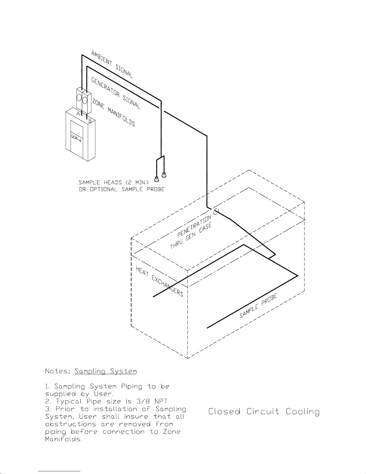
Figure 6 - Closed Circuit “U” Probe
GA0383P02 Rev. C
44

Figure 7 - Open Circuit “Sample Heads”
45
GA0383P02 Rev. C
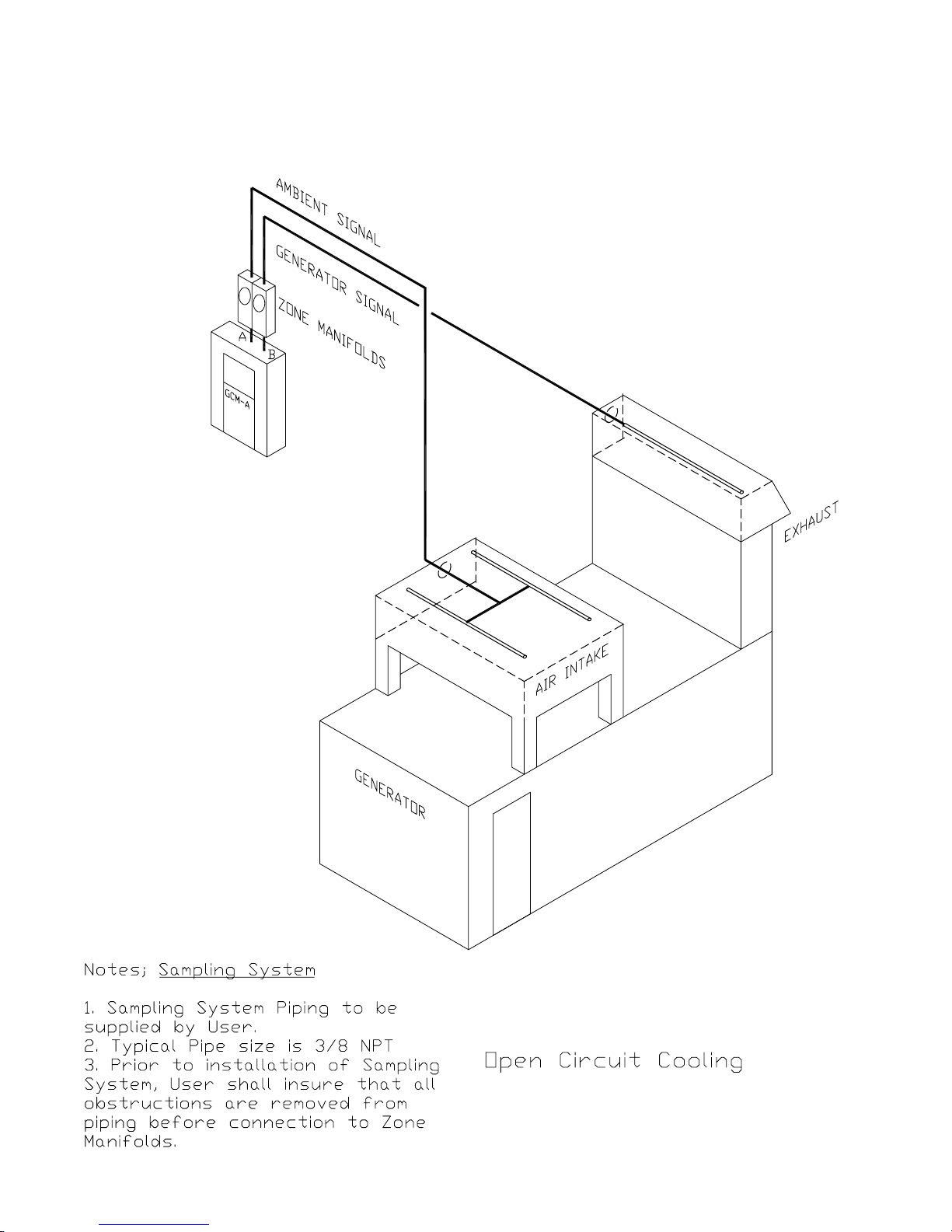
Figure 8 - Open Circuit “Probes”
GA0383P02 Rev. C
46

Figure 9 - Sampling System, 3/8” Typical (PVC)
47
GA0383P02 Rev. C

Figure 10 - Sampling system, 1/2” Typical (PVC)
GA0383P02 Rev. C
48

Figure 11 - Sampling System, 1/2” Flange Configuration
49
GA0383P02 Rev. C

Figure 12 - Zone Manifold
INLET FROM
SAMPLE HEAD
3/8 NPT TYPICAL
BOTH ENDS
THUMB SCREWS
FILTER
3/16 DIA MTG HOLE
TYPICAL
FILTER
FLOW
FLOW ADJUST
P
D
D
P
GA0383P02 Rev. C
OUTLET TO
DECTECTOR
50

Figure 13 - Sample Head
1.25 IN
32 MM
3/8 NPT
SAMPLING HEAD
HOUSING
RETAINING RING
SECTION AA
1.50 IN
38 MM
SCREEN
DO NOT PAINT
51
GA0383P02 Rev. C

Figure 14 - Sample Probe
GA0383P02 Rev. C
52
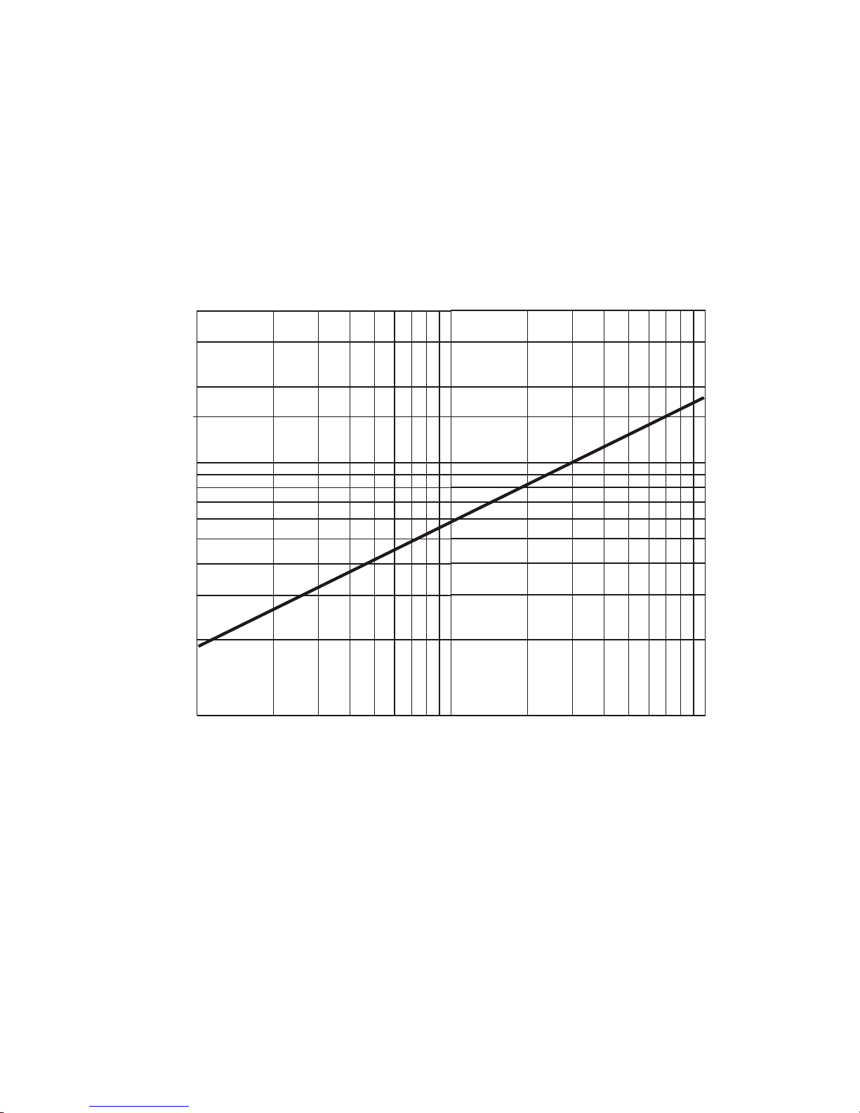
Figure 15 - Zone Manifold Flow,
30
20
14
10
9
8
7
6
5
FLOW LPM
4
∆∆
∆P mm Water
∆∆
3
2
1
.1 .2 .3 .4 .5.6.7.8.91.0 2 3 45678910
ZONE MANIFOLD FLOW P mm WATER
D
53
GA0383P02 Rev. C

Figure 16 - Particle Concentration
l
Particle Concentration vs. GCM-A Output
700
600
500
400
300
Particles/m
200
100
0
0 20406080100
GCM-A Output @ Unity Gain
GA0383P02 Rev. C
54

Figure 17 - Control Panel Detail
55
GA0383P02 Rev. C

Figure 18 - Manifold DP Gage
Instruction Procedure:
1. Place gage on a level surface and check zero. Adjust if necessary, using the adjustment
on the front of the gage.
2. To check flow, remove the caps from the flow differential pressure taps on the manifold.
Connect the + tube (high side) to the + flow differential pressure tap, and the – tube to
the – flow differential pressure tap. (Refer to Figure 4, 5 or 6 of the IFD Samples System
Manual for tap locations on the manifolds.)
3. To check filter differential pressure, connect the gage to the respective + and – filter
differential pressure taps. Always replace caps on unused taps.
From FA0239P01 Rev. A, Appendix A for Manifold Differential Pressure (DP) Gage, Catalog No. FC0041G01
GA0383P02 Rev. C
56

A PCC Flow Technologies, Inc. Company
Environment One Corporation
2773 Balltown Road
Niskayuna, New York USA 12309–1090
Tel: (01) 518.346.6161
FAX: 518.346.6188
www.eone.com
 Loading...