

Page 1

ET201
User’s Manual
Page 2

1
Preface
Dear Users,
Thank you for choosing ET201 Digital storage waveform multimeter. Digital waveform multimeter. It’s an
inevitable way for measuring meter develop from simulate display (pin indicator), digital display to waveform
display. I believe that the creative function combination and user-friendly design of the product will greatly facilitate
your on-site inspection. Please read this user manual carefully before using, especially in the “Safety instruction”
part, and please kindly keep it for your future reference.
Intellectual Property Rights
The Product adopts a combination of proprietary technologies, to purchase or use the instrument doesn’t mean
the owner has the right to transfer any intellectual property. Any action of imitating or applying all or part of the
technologies without our agreement may violate our intellectual rights any define as a tort. The intellectual property
rights include but not limit to patents, trademarks, publications, website contents and so on.
The information provide in this user manual replaces all the previously published information, any change
shall only be announced on our official website.
We reserve the right to change the product specifications, product price and software upgrading.
We reserve the ultimate right of the interpretation for our product using manual and marketing activities.
Page 3

2
Catalogue
PREFACE
.......................................................................................................................................................................................................
1
INTELLECTUAL PROPERTY RIGHTS
.............................................................................................................................................................
1
SAFETY INSTRUCTION
.................................................................................................................................................................................
1
METER INTRODUCTION
.................................................................................................................................................................................
4
GENERAL FEATURES..............................................................................................................................................................4
KEY-PRESS FUNCTION........................................................................................................................................................... 5
BASIC OPERATION
.......................................................................................................................................................................................
6
TURN ON/ SHUT DOWN.......................................................................................................................................................... 6
AUTO SHUTDOWN..................................................................................................................................................................7
BACKLIGHT USING................................................................................................................................................................ 7
BATTERIES REPLACE............................................................................................................................................................. 7
MULTIMETER OPERATION
.............................................................................................................................................................................
7
MULTIMETER PATTERN.......................................................................................................................................................... 7
MEASURING FUNCTION EXCHANGE...................................................................................................................................... 8
RELATIVE VALUE MEASURING (REL) PATTERN..................................................................................................................... 8
APPLICATION OF RELATIVE VALUE MEASURING (REL).........................................................................................................9
Page 4

3
MEASURING DATA HOLD AND STORAGE.............................................................................................................................. 10
MEASURING DATA READOUT AND DELETE.......................................................................................................................... 10
MEASURING DATA READOUT:.............................................................................................................................................. 10
STORED DATA DELETE:.........................................................................................................................................................11
AUTO RECORDING PATTERN................................................................................................................................................ 12
AC/DC VOLTAGE MEASURING............................................................................................................................................ 13
AC/DC CURRENT (MA, 20A) MEASURING......................................................................................................................... 14
FREQUENCY MEASURING.....................................................................................................................................................16
RESISTANCE MEASURING.....................................................................................................................................................17
DIODE/CONTINUITY/REMOTE TEST...................................................................................................................................... 18
DIODE DETECTING:.............................................................................................................................................................. 18
CONTINUITY TEST:............................................................................................................................................................... 18
REMOTE TEST:......................................................................................................................................................................19
CAPACITANCE MEASURING..................................................................................................................................................19
HFE MEASURING:................................................................................................................................................................21
WAVEFORM FUNCTION OPERATION
.............................................................................................................................................................
22
WAVEFORM PATTERN........................................................................................................................................................... 22
FUNCTION KEY AND MAIN MENU........................................................................................................................................ 22
VOLTAGE MEASURING WAVEFORM:..................................................................................................................................... 23
CURRENT MEASURING WAVEFORM:.....................................................................................................................................23
Page 5

4
WAVEFORM AUTO MEASURING............................................................................................................................................ 24
WAVEFORM HOLD AND STORAGE......................................................................................................................................... 25
WAVEFORM STORAGE AND READOUT.................................................................................................................................. 25
DELETING OF THE STORED WAVEFORM................................................................................................................................ 26
TECHNOLOGY PARAMETER AND METER PACKAGE
.......................................................................................................................................
26
METER FEATURES AND TECHNOLOGY PARAMETER............................................................................................................ 26
GENERAL FEATURES:.......................................................................................................................................................... 26
DIGITAL MULTIMETER FEATURES:...................................................................................................................................... 26
DISPLAYING SYMBOL AND ICON
...............................................................................................................................................................
30
THE PACKAGE AND ACCESSORIES
.............................................................................................................................................................
31
Page 6
1
Safety instruction
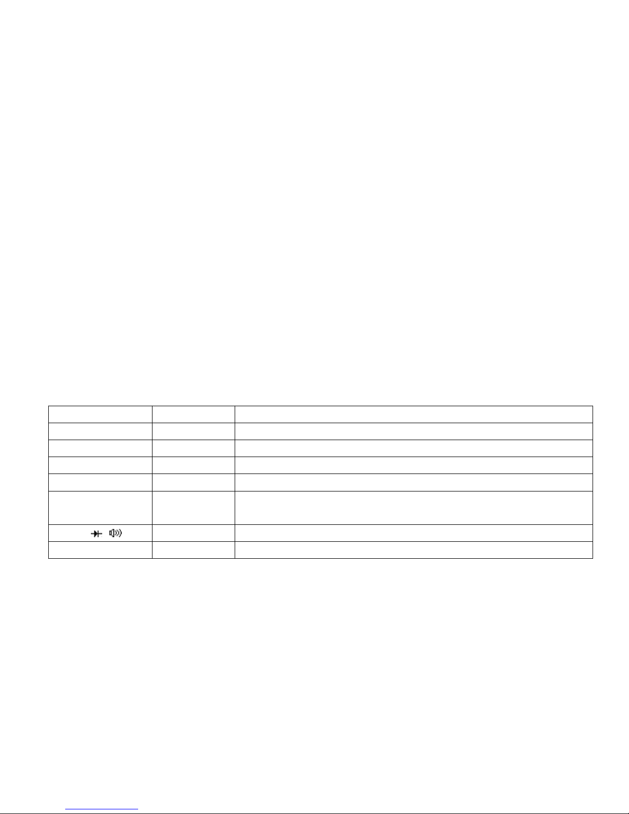
The design of digital storage waveform multimeter ET201 is in accordance with the safety standard of IEC 1010-1, CAT
Ⅲ-600V, the second category of excess voltage electrical measuring. pollution protect grade: 1stgrade.
1. Please check if the housing being damaged or if any accessories lost before using. Crucially, please pay highly
attention to check the insulation of the test pen and connection line. Do not contact the metal part of the test pen during your
using.
2. Operation doesn't allow in below condition: High temperature, Moist, Rainy day, inflammable and explosive, or even
your instrument become wet.
3. It’s completely not permitted to exert overload current/voltage that the instrument can accept during your using.
Measuring Function
Input terminal
Max. Limit
V DC
V/,COM
1000V DC+AC Peak Value,within 10 second
V AC
V/,COM
750V DC+AC RMS,within 10 second
Hz
V/,COM
250V DC/AC RMS,within 10 second
mA AC/ DC
200mA,COM
500mA DC/AC RMS,250V/400mA burnt fuse
A AC/ DC
20A,COM
20A DC/AC RMS,within 30 second,15min cooling diapauses, 500V/20A burnt
fuse
/ /
V/,COM
250V DC/AC RMS,within 10 second
Capacitance
V/,COM
250V DC/AC RMS,within 10 second
Page 7

2
4. Please do remember to remove the pin of the test pen from the testing point when you are trying to exchange the
measuring function, pull/insert the plug of the test pen or turn on/ shut off the instrument.
5. Please pay attention to the safety warning signal displayed on the instrument: when the input voltage exceeds
DC1000V/AC750V, the buzzer will make a long alarm sound; and it will beep for three times when the input over the safety
voltage (36VDC/25VAC) under the measuring range of DC1000V/AC750V.
6. Please do not organize voltage measuring job when the voltage-to-ground reach 500V which showing on the reference
input terminus "COM" of the instrument.
7. It will be extremely dangerous in mistaken operation of voltage measuring even though there is a 500V fuse installed in the
20A measuring range
8. The test pen is definitely not allowed to touch the two terminal of the voltage source when choosing below measuring
function: current, resistance, continuity, diode, capacitance and so on.
9. Before conducting the resistance and diode/continuity test, please cut off the power of the measurand and make sure the
capacitor of the power supply circuit has discharge completely.
10. The instrument power must be cut off and the test pen must be removed from the circuit before replacing for the fuse in
the backboard of the instrument. And the fuse specification should be kept in same accordingly.
11. Product and accessories should not be reconstructed, separated or taken into other usage beyond the original function
design; meanwhile, all of the accessories or enclosure can't be random replaced.
12. Please don't electricize for ordinary batteries, and please replace the batteries when low power prompted in the
screen.
Page 8
3
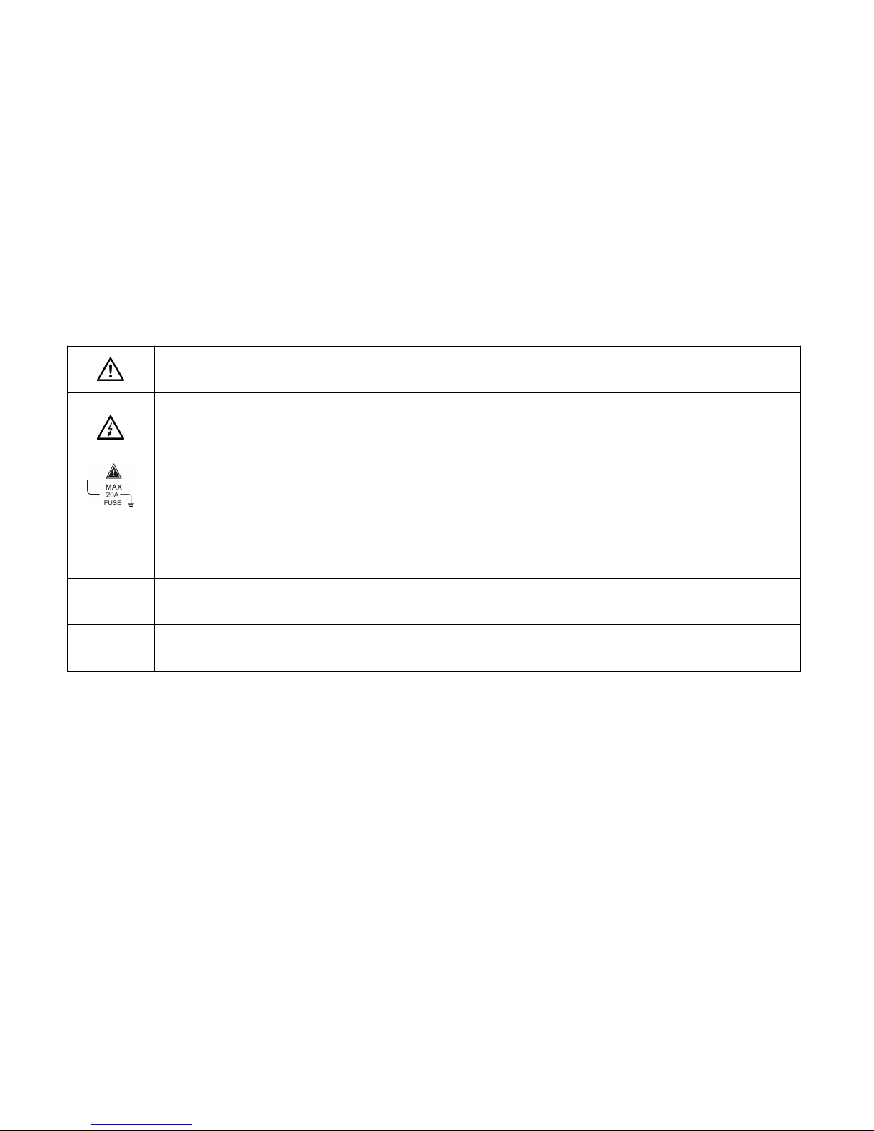
Safety Symbol:
Dangerous! When this symbol marks beside other sign or lies near the socket terminal, it indicates that the
operator must obey the manual instrument for use.
Electric shock dangerous! When this symbol marks on one or more using terminals, it indicates that it may
carry dangerous voltage during using. To guarantee your safety as much as possible, please don't touch the
testing terminal of the test pen with your hand.
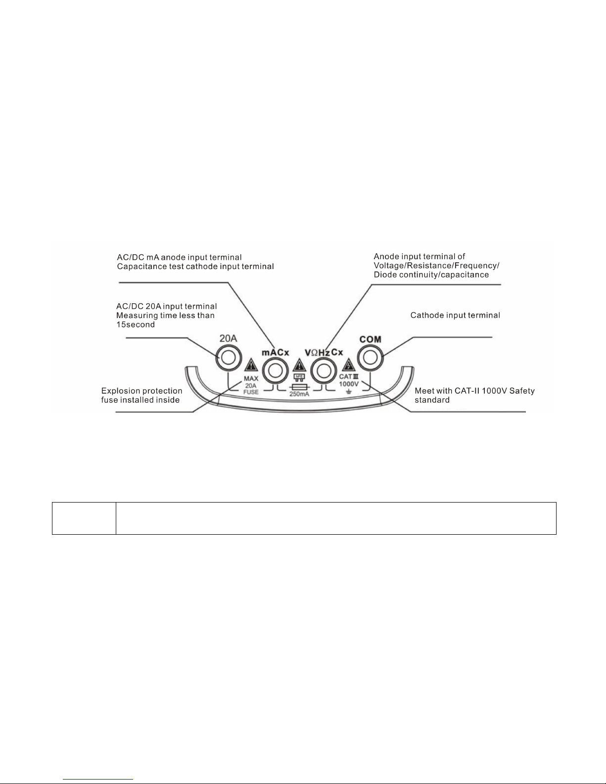
When this symbol lies near the connection terminal, it indicates that the Max acceptant current between the
terminal and the COM is 20A. "FUSE" means that there is a 20A internal fuse (250Ma) installed. And it's
strictly forbidden to measure the circuit current when the AC voltage is over 250V
Prompt!
The Prompt statement indicates that you should be careful because mistaken operation may lead to wrong testing
result or accessories damaged.
Attention!
The Attention statement indicates that you must be pretty careful because mistaken or disobeyed operation may
damage the product or possibly cause extra properties loss.
Warning!
The Warning statement indicates that you should be as much as concentrated because mistaken or disobeyed operation
may cause people injuries or even life danger.
Page 9
4
Meter introduction
General Features
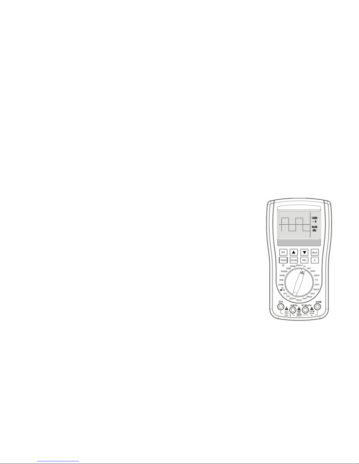
• 200k high-speed A/D data collecting, 2000 count digital multimeter, one-key transform to waveform function during
measuring.
• With Panel calibration technology, more reliable since calibration factor setting inside and no need to adjust the
potentiometer.
• 100 groups of data and 3 wave forms storage
• Waveform hold and data hold.
• Automatic waveform capture.
• Voltage/Current range auto-recording, which facilitates online test.
• Uniquely record readout; synchronously display historical data and real-time measurement.
• Relative value measurement, effectively eliminate lead-wire resistance or interference signals.
• Automatic shutdown and manually abolish automatic shutdown.
• With function of measuring DC/AC Current, DC/AC Voltage, resistance, capacitance,
Frequency, Diode/Continuity, HFE and Remote control test
• 2 kHz~200 kHz automatically exchange measuring range of frequency detecting, Max. input
380V.
• 20A AC/DC Current measuring,φ10X38 fuse installed inside.
• White backlight, manually control, which convenient for dim light operation and data readout
Page 10
5
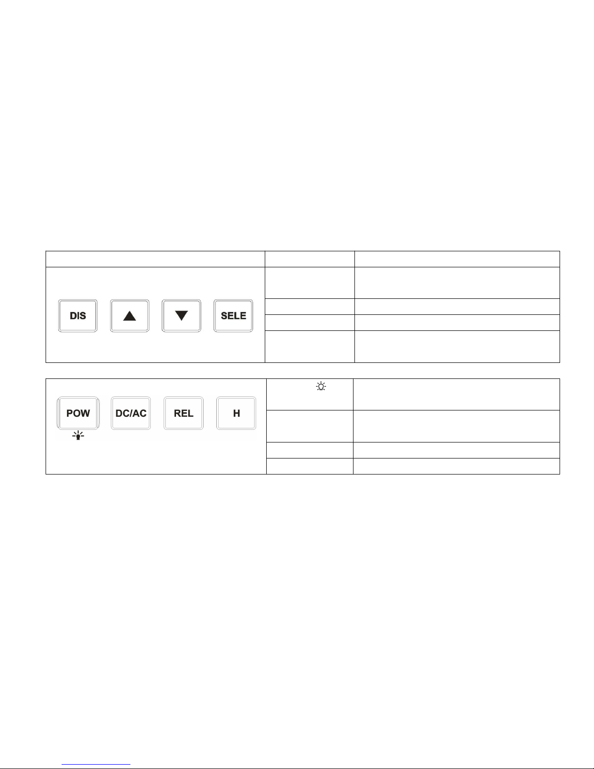
Key-press Function
Key-press
Name
Function
Dis
Exchange between Multimeter/Waveform meter;
waveform storage readout.
Page up
Data storage/Waveform readout Page up
Page down
Data storage/Waveform readout Page down
Sele
Automatic select vertical amplitude and time
base to display waveform
Pow
Control instrument power and the backlight of
LCD off/on
DC/AC
Select measurement between direct current(DC)
and alternating current (AC)
REL
Measuring relative value
H
Data hold/Waveform storage
Page 11
6
Input socket
Basic operation
Turn on/ Shut down
Press the key of “Power” and stay for more than 2 second, meter turn on, press again for more than 2 second, it will be
shut down
Attention!
• Please do remember to remove the test probe form the test point before shut down.
• Keep the electric power turned off when finished the using.
Page 12
7
Auto shutdown
The meter will be shutdown in 15 minutes if there is none press operation. To cancel the automatic shutdown function,
please press the key of “waveform readout” and “Power” in turn.
Backlight Using
Using backlight function can improve the effectiveness of display under dim measuring condition, however, overuse the
backlight may reduce the continuously working time of the batteries. Press the power key to light it up, it will hold on for
30 second and then automatically shut off; press again to shut it off manually.
Batteries Replace
When it shows with low power sign at the top right corner of the LCD screen during the using, please replace the
batteries as soon as possible. It’s better to take out the batteries if you don’t use the meter very often, in case for electrolyte
leakage which may damage the meter.
Warning!
Please don’t recharge for the equipped batteries! Use the powerful batteries for replacement.
Multimeter Operation
Multimeter pattern
Warning!
•Please thoroughly read, understand and obey the safety rules and operation standards mentioned below.
• Please remove the probe of the test pen from the test point when changing measuring function.
Page 13

8
Measuring Function Exchange
Rotary switch, select the measuring function and the proper measuring range.
Voltage measuring range: 200mV, 2V, 20V, 200V, 1000V (Notice that AC measuring is 750V RMS)
Frequency measuring range is automatically select, included 2 kHz/20kHz/200kHz
4 Capacitance measuring ranges, from 20nF to 200μF
4 Current measuring ranges, from 2mA to 20A
6 Resistance measuring ranges, from 200Ω to 20MΩ
Continuity test/ Remote test/ Diode test/ HFE test
Relative value measuring (REL) pattern
Relative value measuring pattern is the one that displays the D-value between the “real value” and “reference value”.
Most function of this meter can run the REL pattern.
1. When you press the “REL” key, the currently testing data will be storage as a “reference value”, and then the REL
pattern will be active.
2. LCD will display symbol “” to represent that the REL pattern has been actived.
3. The data displayed on the screen is the D-value between the current “real value” and the stored “reference value”.
4. Press the “REL” key again to exit the “REL” pattern.
5. “REL” pattern will be automatically relieve when changing function or measuring range
Page 14
9
Application of Relative value measuring (REL)
1. Apply in Voltage measuring: If LCD has original data displayed, once you active the REL function, the LCD screens will
display symbol “”, meanwhile, the original data will be counteract and showing as “000” (Resolution depends on your
measuring range), and then go on to voltage test as normal.
2. Apply in Resistance measuring: Switch the testing range to “Resistance measuring” and then insert the test pen with two
metal probe reliable connected (short-circuit), observe the reading, if initial reading existed, press the “REL” key and
then the LCD screen will display symbol “”, meanwhile, the original data will be counteract and showing as “000”
(Resolution depends on your measuring range), and then go on to Resistance test as normal.
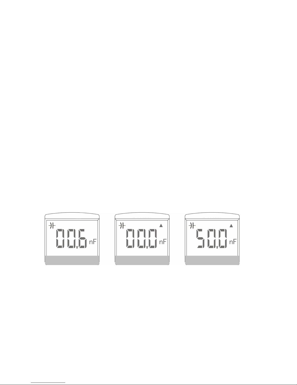
3. Apply in Capacitance measuring: Switch the testing range to “Capacitance measuring” and then insert the test pen with
two metal probe in open-circuit state, observe the reading, if initial reading existed, press the “REL” key and then the
LCD screen will display symbol “”, meanwhile, the original data will be counteract and showing as “000” (Resolution
depends on your measuring range), and then go on to Capacitance test as normal.
Page 15
10
Prompt!
• Some measuring range may exist interference, it’s normal that the reading can’t return zero or will float
slightly when active the REL measuring pattern.
•
Please remember to relieve the REL measuring pattern after finished the measurement.
Measuring data hold and storage
Both holding and storing measuring data are completed with one key. The displaying reading will be stored once
pressing the key of “storage”, and the LCD screen will display the data storage icon “H00-H99” at the same time. It will return
to normal running if you press the key again, anyway, the holding data has been stored in the internal storage.
1. If you need to load the current measured value into the database, please press the “Storage” key to keep it down.
2. Once the data being stored, press the “waveform/readout” key and stay for 2 second to enter the database, you can check
the stored data.
3. Once the meter gets into data holding state, it can only display the stored data when press the “waveform/readout” key,
and it’s unable to get into waveform state at this time.
4. Holding state will be existed automatically when changing measuring range or measuring function.
Measuring data readout and delete
Measuring data readout:
The database of this meter is equipped with the capacity of storing 100 DMM measuring data.
1. Press the “waveform/readout” key and stay at least 2 second to enter the database of the meter.
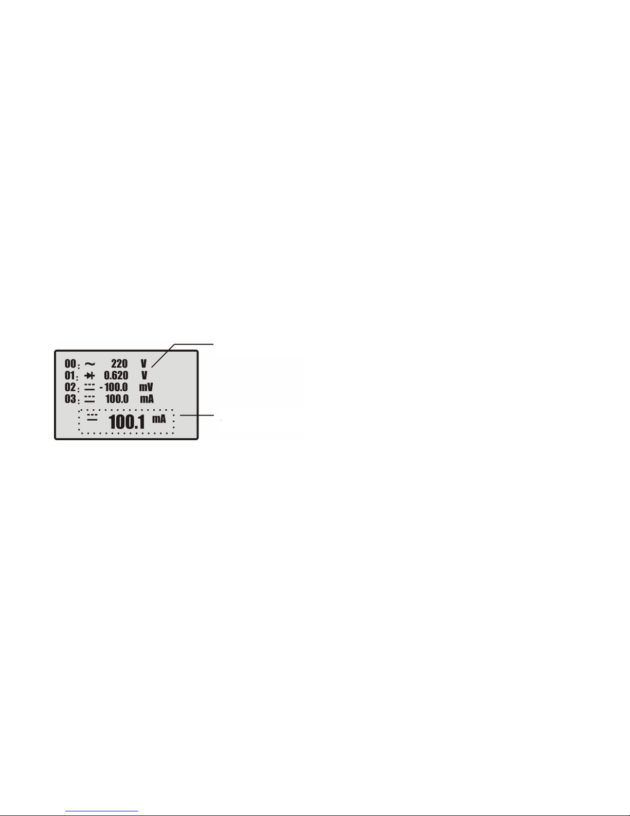
2. In the state of “data readout”, the bottom screen of the meter will appear a window (window of the real-time measuring
data) and the data will be renovated all the time.
Page 16
11
3. In the database, LCD will list out 4 storage location of the current page and indicates whether there has data being stored
in this location
4. If there has data being stored in one location, both its numerical value and unit will be listed out.
5. The list sequence will change if pressing the “ ” key, and it counts form H00 to H99, besides, there will be 4 groups of
stored data display on each page.
6. Press the “waveform/readout” key and stay at least 2 second to exit the “measuring data readout” state.
Stored data delete:
1. Press the “Auto” key and stay at least 2 second, LCD screen will display a symbol of “recycle bin”
2. Press the “Storage” key, LCD screen will display a symbol of “waiting”, it means the stored data is being deleted.
3. it’s unable to delete the data for a single line or single page, as a result, once you active the delete program, all the stored
data (H00-H99) will be deleted.
Display the historical stored data
Display the current measuring value
Page 17

12
4. When data delete program finished, it will automatically get into measuring state.
Auto recording pattern
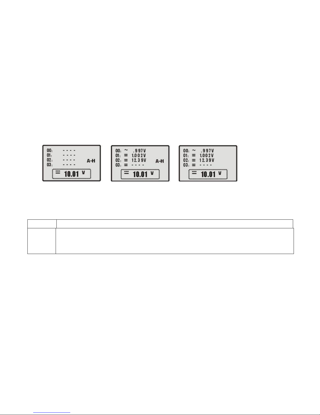
The auto recording pattern is able to display and auto record signals beyond 10 digits under the current measuring range.
When the test pen removes from the testing point, it will run and record a new measurement with the amplitude verified rule.
a. Press the “Storage” key and stay for 2 second, LCD screen will transform to Auto record frame, auto record function
activated.
b. Press the “Storage” key to cancel the A-H symbol and exit auto recording pattern. You can press the “ ” key to
check the record list and store the data simultaneously. Once auto record data being stored, the current measuring data
will only be listed behind when storing.
c. Press the “Storage” key to cancel the A-H symbol and exit the auto recording pattern, and then press the
“waveform/readout” key returning to normal measuring state.
Press “Storage” key to get into
data storage state
Press “Auto” key to get into deleting
program
Press “storage” key again to confirm deleting
Wait for a moment, symbol disappeared,
deleting finished.
Page 18
13
d. Only when the testing data displayed stably can it being record and it needs a few second for the record completed.
e. All previously stored data will be deleted once you get into the auto record pattern.
AC/DC Voltage measuring
Prompt!
You should be careful when the measuring voltage exceed the “Safety voltage” (36V DC/25V AC).
Warning!
• To avoid the meter from being damaged, it’s not allow to input the voltage of 750V AV or 1000V DC more
than ten seconds during testing.
• The measuring voltage reach to the utmost degree, please operate carefully.
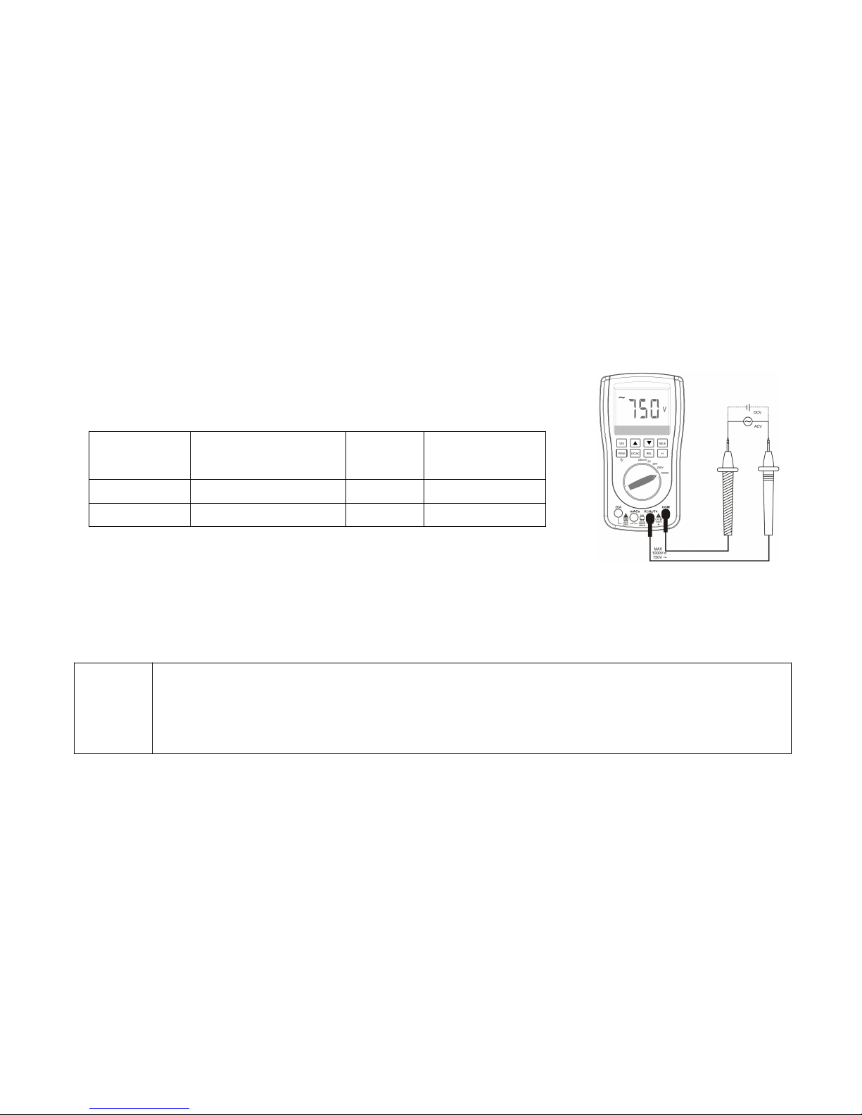
1. Put the banana plug of the black P-wire into the cathode COM socket, and the red one to the anode V socket.
2. Spin the function switch to select a proper range (200mV~1000V) according to the testing signal.
3. Press the “AC/DC” key to determine the AC/DC function, and then there will be a “~” or “---“symbol displayed on the top left
of the screen.
Press “Storage” key to get into
Auto recording pattern.
Automatically record the
measuring data for the test
Press the “Storage” key again to exit auto
recording pattern, and then press the “
”
key to check the record
Page 19
14
4. Connect the testing points with the test pen.
5. Read the voltage displayed on the screen, it may include the numerical value, decimal point and cathode/anode
determined.
Voltage measuring menu:
REL Pattern
Data hold/Auto record
Pattern
AC/DC
Function
Waveform/Readout
Function
REL
H00/A-H
~/---
REL(Clear)
Store
AC/DC
Waveform/Readout
a. Press the “REL” key to enter REL pattern.
b. Press the “Storage” key to enter Data hold/store/Auto record pattern.
c. Press the “AC/DC” key to select the AC/DC function
d. Press the “Waveform/Readout” key to enter the waveform pattern; it will display the waveform of the current voltage or a
list of stored data and waveform.
AC/DC Current (mA, 20A) measuring
Warning!
• It’s strictly prohibit using the 20A input terminal to measure the voltage; please don’t operate a AC current
measuring in a circuit with voltage over AV 250V.
• Do not test over 15 second in every 15 minutes when using the 20A Current measuring range. Otherwise,
the meter and test pen connecting wire may be damaged.
AC/DC Voltage measuring illustration
Page 20
15
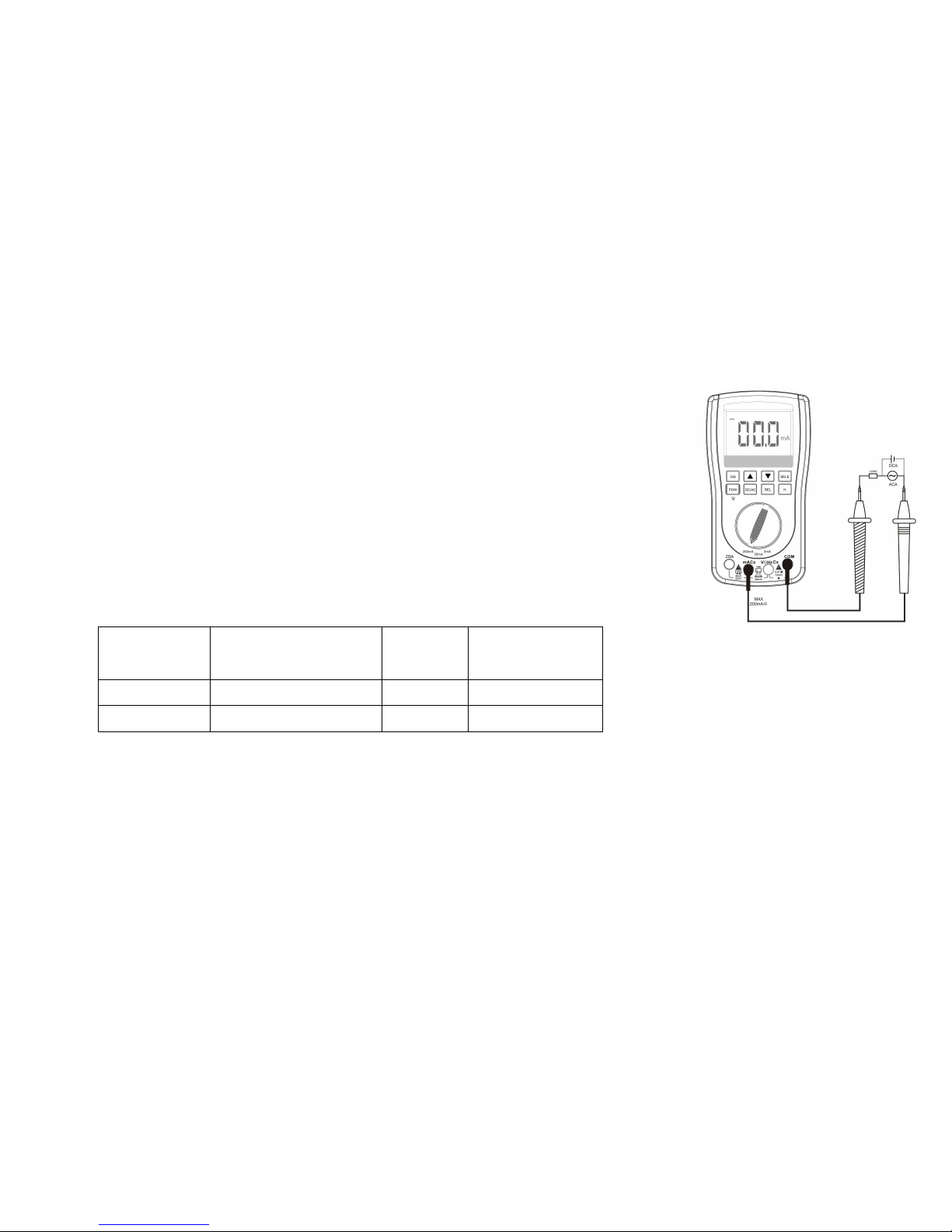
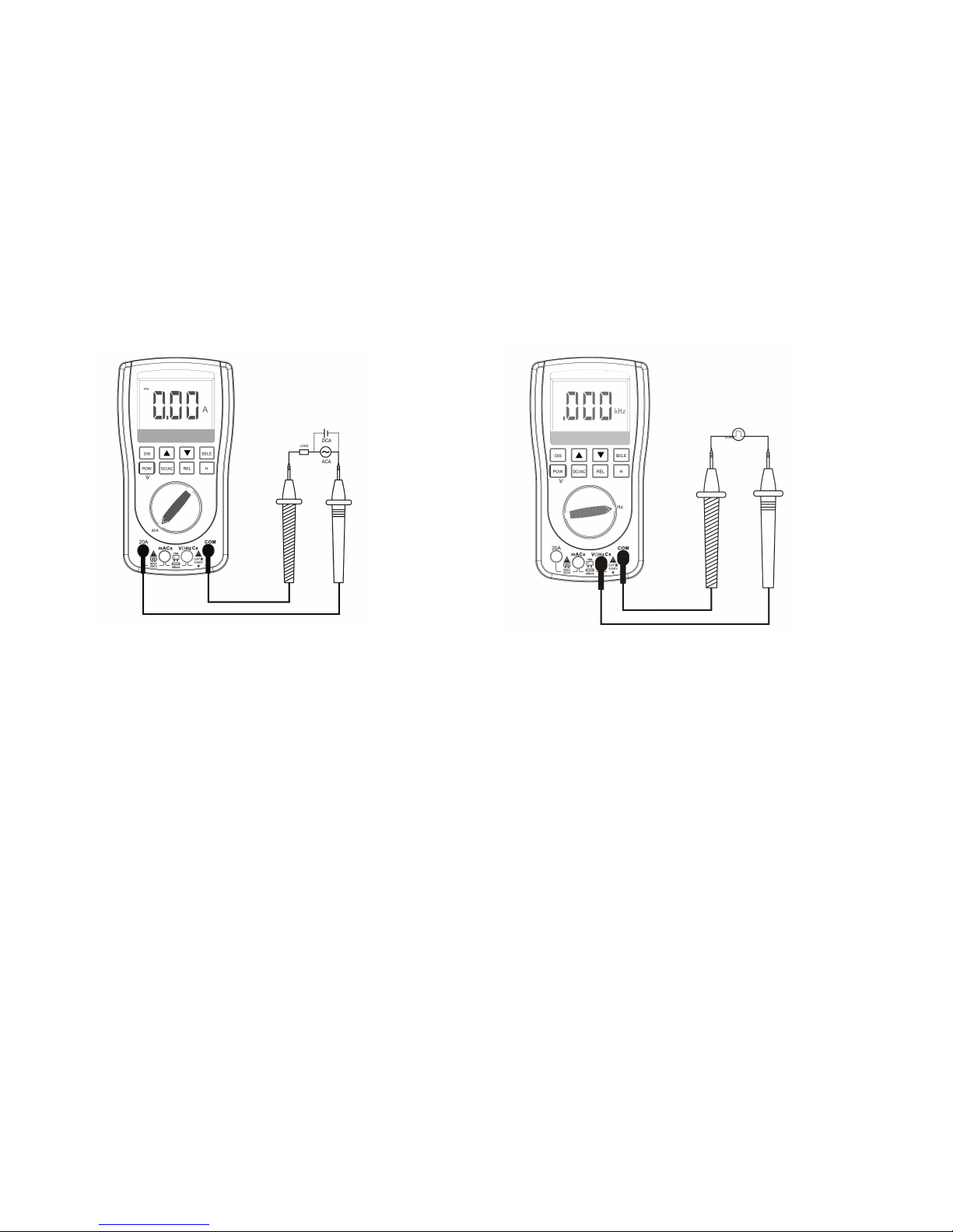
1. Put the banana plug of the black P-wire into the cathode COM socket, and the red one to the anode mA socket. (20A
measuring should insert in the 20A input terminal)
2. Spin the function switch to select a proper range (2mA~200mA(20A)) according to the
testing signal.
3. Press the “AC/DC” key to determine the AC/DC function, and then there will be a “~” or
“---“symbol displayed on the top left of the screen.
4. Connect the circuit with the test pen.
5. Read the current displayed on the screen, it may include the numerical value, decimal
point and cathode/anode determined.
Current measuring menu:
REL Pattern
Data hold/Auto record
Pattern
AC/DC
Function
Waveform/Readout
Function
REL
H00/A-H
~/---
REL(Clear)
Store
AC/DC
Waveform/Readout
a. Press the “REL” key to enter REL pattern.
b. Press the “Storage” key to enter Data hold/store/Auto record pattern.
c. Press the “AC/DC” key to select the AC/DC function
d. Press the “Waveform/Readout” key to enter the waveform pattern; it will display the waveform of the current voltage or a
list of stored data and waveform.
mA Current measuring illustration
Page 21
16
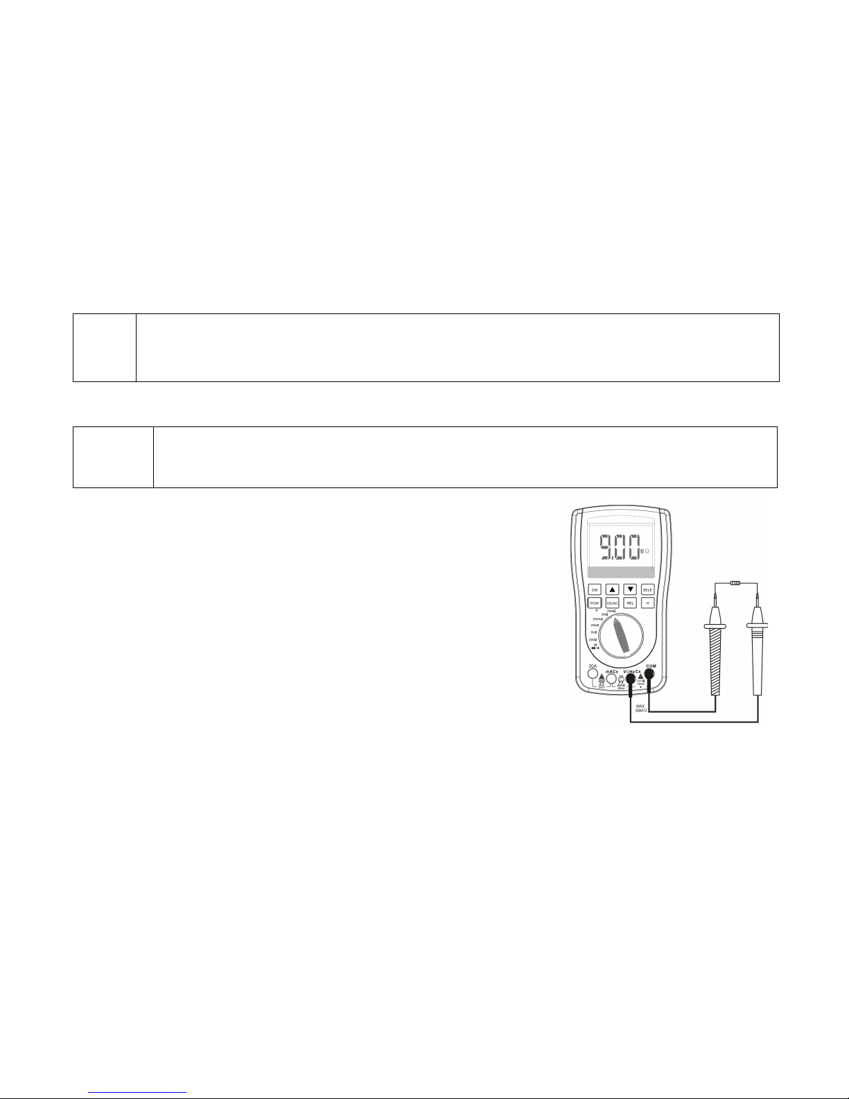
Frequency measuring
Frequency measuring, a extended function of the AC Voltage measuring.
1. Put the banana plug of the black P-wire into the cathode COM socket, and the red one to the anode V socket.
2. Spin the function switch to the Hz measuring range.
3. Connect the testing point with the test pen.
4. Read the Frequency displayed on the screen, it may include the numerical value, decimal point and cathode/anode
determined.
20A Current measuring illustration
Frequency measuring illustration
Page 22
17
Prompt!
It’s neither able to use the waveform display nor the REL function in the frequency measuring!
In the function of frequency measuring, the width of the testing signal should be no less than 2Vp-p, and the
utmost input voltage should lower than 380V.
Resistance measuring
Warning!
To prevent electric shock, you should firstly cut off the electric power of the measurand ( take off the
batteries/ pull out the power wire), and discharge the capacitance of the electric power supplier.
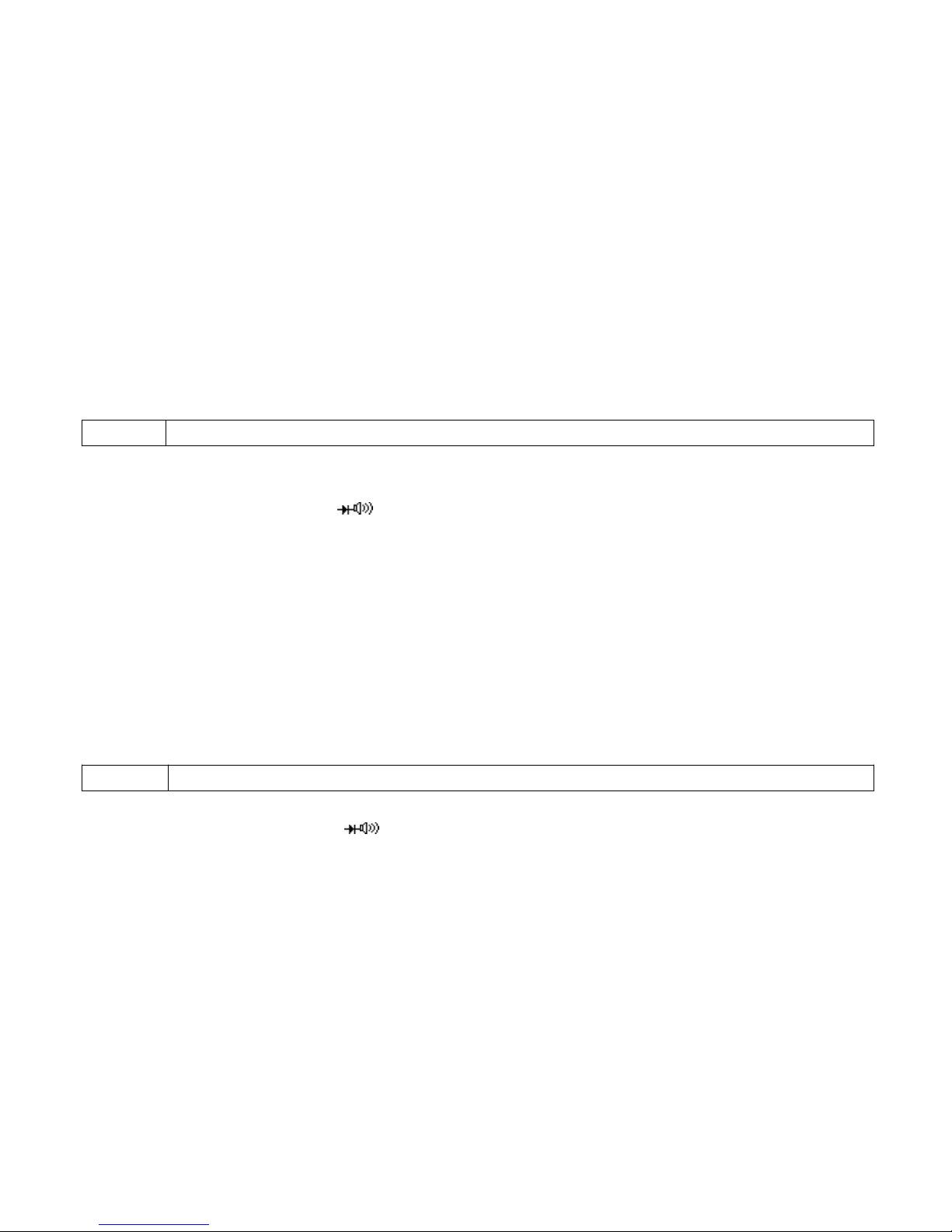
1. Put the banana plug of the black P-wire into the cathode COM socket, and the red
one to the anodesocket.
2. Spin the function switch to select a proper range (200Ω~20MΩ) according to the
magnitude of the Resistance.
3. Cross connect the circuit or component with the test pen, it’s better to take off the
tested component for the measuring to make sure other part of the circuit won’t
affect the accuracy of the measuring result
4. Read the Resistance displayed on the screen, it may include the numerical value,
decimal point and cathode/anode determined.
Resistance measuring illustration
Page 23
18
Diode/Continuity/Remote test
Diode detecting:
Warning!
To prevent electric shock, please do not detect the diode with voltage carried.
1. Put the banana plug of the black P-wire into the cathode COM socket, and the red one to the anode socket.
2. Spin the function switch to select the measuring range.
3. Cross connect to both sides of the tested diode or the PN-junction of the semiconductor. Be notice to the reading
displayed on the meter.
4. Exchange the position of the test pen to reverse its polarity. Be notice to the reading displayed on the meter.
5. The performance of the Diode or PN-junction of the semiconductor can be determined according to below situation:
If one reading displayed a voltage value (approximately 0.2V-0.7V) and the other displayed as “O.L”. It means the diode is
fine.
If both readings displayed as “O.L”, it means the diode break.
If both readings are low or shown as zero, it means the diode short-circuited.
Continuity test:
Warning!
To prevent electric shock, please do not operate a continuity test in a circuit carried with voltage
1.Put the banana plug of the black P-wire into the cathode COM socket, and the red one to the anodesocket.
2.Spin the function switch to select the measuring range.
Page 24
19
3.Connect the circuit with the test pen, if the Resistance less than 100Ω, the buzzer will sound.
Remote test:
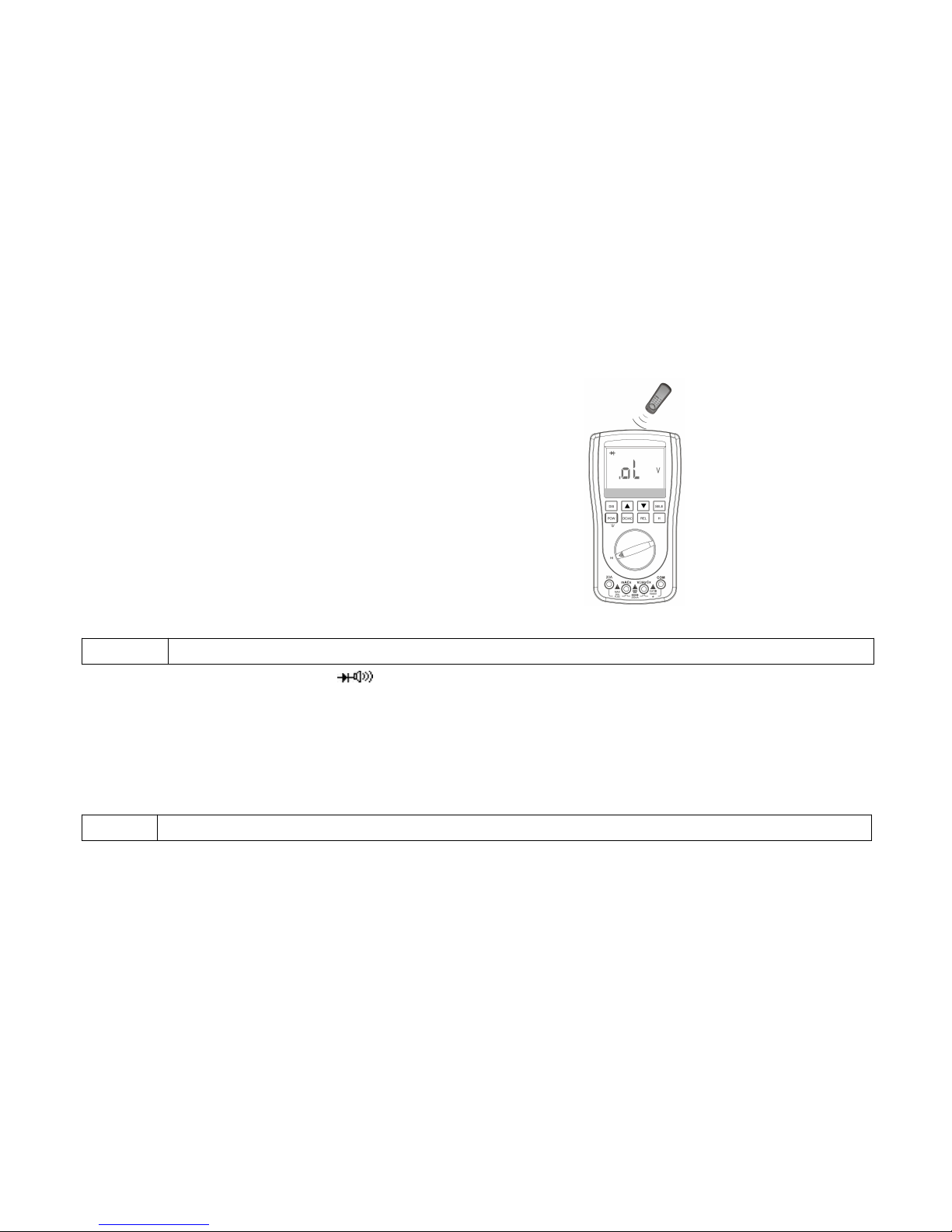
Prompt!
It’s specialized designed for the 38kHz frequency remote control test.
1. Spin the function switch to select the measuring range.
2. Turn on the power of the tested Remote control, press a key randomly and make the transmitting terminal aim at the top of
the meter, if the buzzer makes a sound, it means the remote control work healthily, and otherwise, something may be wrong
with it.
Capacitance measuring
Warning!
To prevent electric shock, please do not detect the Capacitance with voltage carried.
Continuity test illustration
Remote test illustration
Page 25
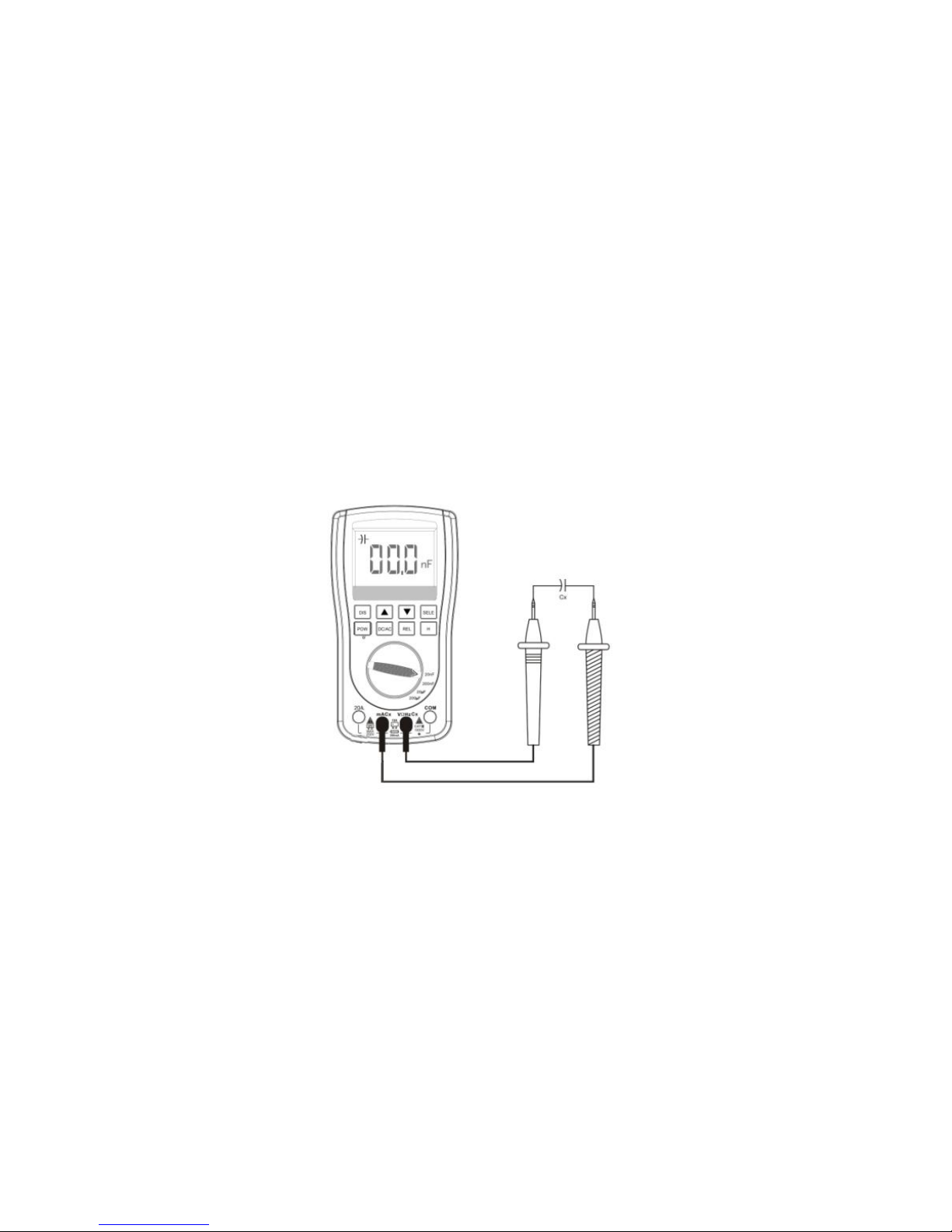
20
1. Put the banana plug of the black P-wire into the cathode mA socket, and the red one to the anode Cx socket.
2. Spin the function switch to select a proper range (20nF~200μF) according to the magnitude of the Capacitance..
3. When measuring for small Capacitance, please press the “REL” key to counteract the lead-wire or distributed capacitance.
4. Contact the metal pins of the Capacitance with the test pen.
5. Read the Capacitance displayed on the screen, it may include the numerical value, decimal point and cathode/anode
determined.
Capacitance test illustration
Page 26
21
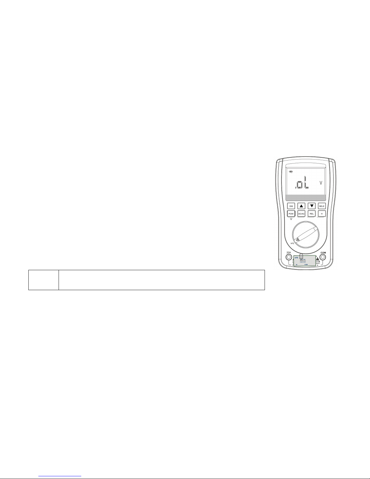
HFE measuring:
1. Insert the accessories of the measured transistor into the mA and COM input terminals
2. Spin the function switch to the HFE range
3. Judge the polarity of the measured transistor and insert its metal pins into the corresponding
EBC jacks of the (NPN or PNP) transistor.
4. Check the amplification (HFE value) displayed on the screen. If there is no display on the
LCD, check whether the transistor pins are contacted correctly, if not, it indicates that the
measured transistor may have been damaged.
Attention!
You can’t measure the voltage signal with the input terminal if you haven’t
inserted the accessories, otherwise, the meter will be damaged!
Dynatron test illustration
Page 27
22
Waveform Function Operation
Waveform pattern
Press the “Waveform/Readout” key to select the waveform function.
Prompt!
Waveform function only applies in the Voltage/Current measuring range.
Function key and Main menu
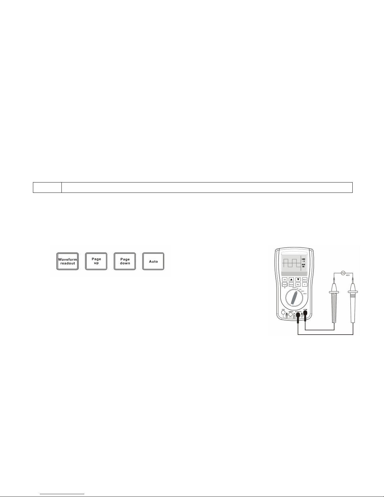
The waveform function key lies below the LCD screen. Coordinated with the different key enables you operate with multiple
functions.
Prompts of the meter’s basic operation written detailed below:
Page 28

23
Waveform pattern
Amount of
waveform display
Auto measuring
Waveform store
Waveform/Readout
Page up/Page
down
Auto
Storage
Measuring/Waveform
Change
Period/Frequency
Stable waveform
display
5 groups of waveform
Voltage measuring Waveform:
1. Put the banana plug of the black P-wire into the cathode COM socket, and the red one to the anode V socket.
2. Spin the function switch to select a proper range (200mV~1000V) according to the magnitude of the measured signal.
3. Contact the test points with the test pen.
4. Press the “Waveform/Readout” key to display the present Voltage waveform.
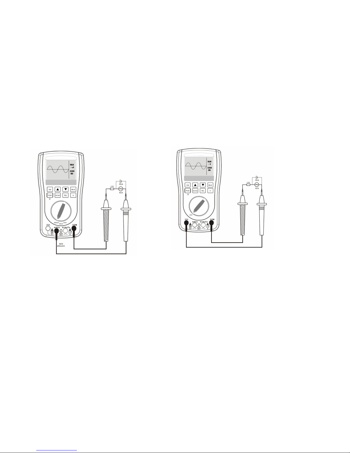
Current measuring Waveform:
1. Put the banana plug of the black P-wire into the cathode COM socket, and the red one to the anode mA socket.
2. Spin the function switch to select a proper range (20mA~200mA) according to the magnitude of the measured signal.
3. Use the test pen series-connected to the circuit.
4. Press the “Waveform/Readout” key to display the present Current waveform.
5. Please refer to the Current measuring section for the connected pattern of the 10A Current waveform measuring.
Page 29
24
Waveform Auto measuring
The waveform meter can automatically measure the Width and Frequency of the current waveform, and the test result
will show on the left of the waveform display area.
The measuring result of the waveform width is a RMS value due to the direct sampling way of the multimeter. (A/D)
Page 30

25
Press the“Auto”key and the LCD will display the stable waveform.
Waveform hold and storage
The main function of waveform hold is to preserve the current waveform for the meticulous observation. Beside, to store
the current waveform in the database, it needs to be hold previously.
The way to hold the waveform: press the“Storage”key and the waveform will be hold, meanwhile, it will display H0~H4
on the down right area of the LCD which indicates the sequence of the 5 groups of waveform.
Waveform storage and readout
The database of the meter can accommodate 5 groups of the waveform data. Please check below for the storage
operation:
1. Press the “Storage” key to enter the waveform storage function
2. Press the “Waveform/Readout” key and stay for 2 second to enter the waveform database.
3. The LCD screen will illustrate the state of the position where 5 groups of waveform listed.( H0-H4)
4. If there has data being stored in the selecting position, thumbnail and relative parameter will be displayed on the
waveform preview area. And it will display a blank coordinate instead if there is no stored data.
Page 31

26
Deleting of the stored waveform
1. Press the “Auto” key and stay at least 2 second, then the LCD will display a symbol of “recycle bin”.
2. Press the “Storage” key, LCD screen will display a symbol of “waiting”, it means the stored data is being deleted.
3. It’s unable to delete the data for a single line or single page, as a result, once you active the delete program, all the
stored data (H00-H99) will be deleted.4. When data delete program finished, it will automatically get into measuring state.
Technology parameter and Meter package
Meter Features and Technology Parameter
Page 32
27
General Features:
Display
128 64 dot-matrix LCD display
Observe area
60mm x40mm
Backlight
White
Resistance
10MΩ
Batteries
AAA 1.5V × 4
Auto power off
yes
Low power warning
Power dissipation
Lower than 20mA
Using time expectancy
About 50 hours
Storage
100 groups DMM, 5 groups of
waveform
Using condition
0°C~+40°C;<75%RH
Store condition
-10°C ~ +60°C ; <90%RH
Dimension
100 mm 186 mm 45mm
Weight
370g (exclude other accessories)
Digital Multimeter Features:
The Accuracy of all measuring range expressed as: ±(a% rdg+ dgt). The meter should be regulated periodically and
normally once a year. It should meet below environment condition to keep the accuracy: 23°C±5°C、<75%RH
Page 33
28
Analog bandwidth
10kHz
Max. current sampling rate
200ksps
Function
Range
Resolution
Accuracy
DC Voltage
200.0mV
0.1mV
(0.75%rdg + 10dgt)
2.000V
1mV
20.00V
10mV
200.0V
100mV
1000V
1V
(1.5%rdg + 10dgt)
AC Voltage
200.0mV
0.1mV
(1.0%rdg + 10dgt)
50Hz~400Hz
2.000V
1mV
20.00V
10mV
200.0V
100mV
750V
1V
(1.5%rdg + 10dgt) 50Hz~400Hz
DC Current
2mA/20mA/200mA
1µA /100µA
(1.2%rdg + 10dgt)
20.00A
10mA
200.0
0.1 Ω
2.000k
1 Ω
Page 34
29
Resistance
(1.0%rdg + 5dgt)
20.00k
10 Ω
200.0k
100 Ω
2.000M
1k
20.00M
10k
(3.0%rdg + 5dgt)
Capacitance
20.00nF
10pF
(2%rdg + 10dgt)
200.0nF
0.1nF
(1%rdg + 3dgt)
20.00μF
10nF
(1%rdg + 3dgt)
200.0μF
0.1μF
(1.5%rdg + 3dgt)
Frequency
2KHz~200KHz
1Hz
(1.0%rdg + 5dgt),(signal width should be
no less than 2Vp-p,AC V,MAX380V)
Diode test
The open-circuit voltage is about 1.5V and the Max. measuring current is about 1.5mA
Continuity
The detected Resistance is about 100Ω
Remote test
38kHz Carried Frequency
HFE
30~1000(Check the Attachment)
Fuse’s specification
Φ5×20,250mA/250V
Page 35

30
Displaying symbol and icon
A
Ampere
AC ~
Alternating current
COM
Measuring reference terminal(near
the plug of the input reference
terminal)
DC
Direct current
F
Farad(Capacitance unit)
hFEMagnification of the transistor
HOLD
Data/Waveform hold
Hz
Hertz(Frequency unit)
mA
Milliamp
mV
Millivolt
nF
Nanafarad (Capacitance unit)
Relative value(REL)
V
Volt
F
Microfarad(Capacitance unit)
Ohm(Resistance unit)
Page up/down
Sound, Continuity test
Remaining electric power
Diode
Safety warning(Prompt of the Harmed or the
utmost voltage/current)
Page 36

31
The Package and Accessories
Package:
ET201 test set×1, Double-plastic molding test pen ×1, Oxford bag ×1, Product manual ×1
 Loading...