

EOM-POS EOM-375 Quick Setup Manual
Wireless Barcode Scanner
Quick Setup Guide
Reset toDefaults
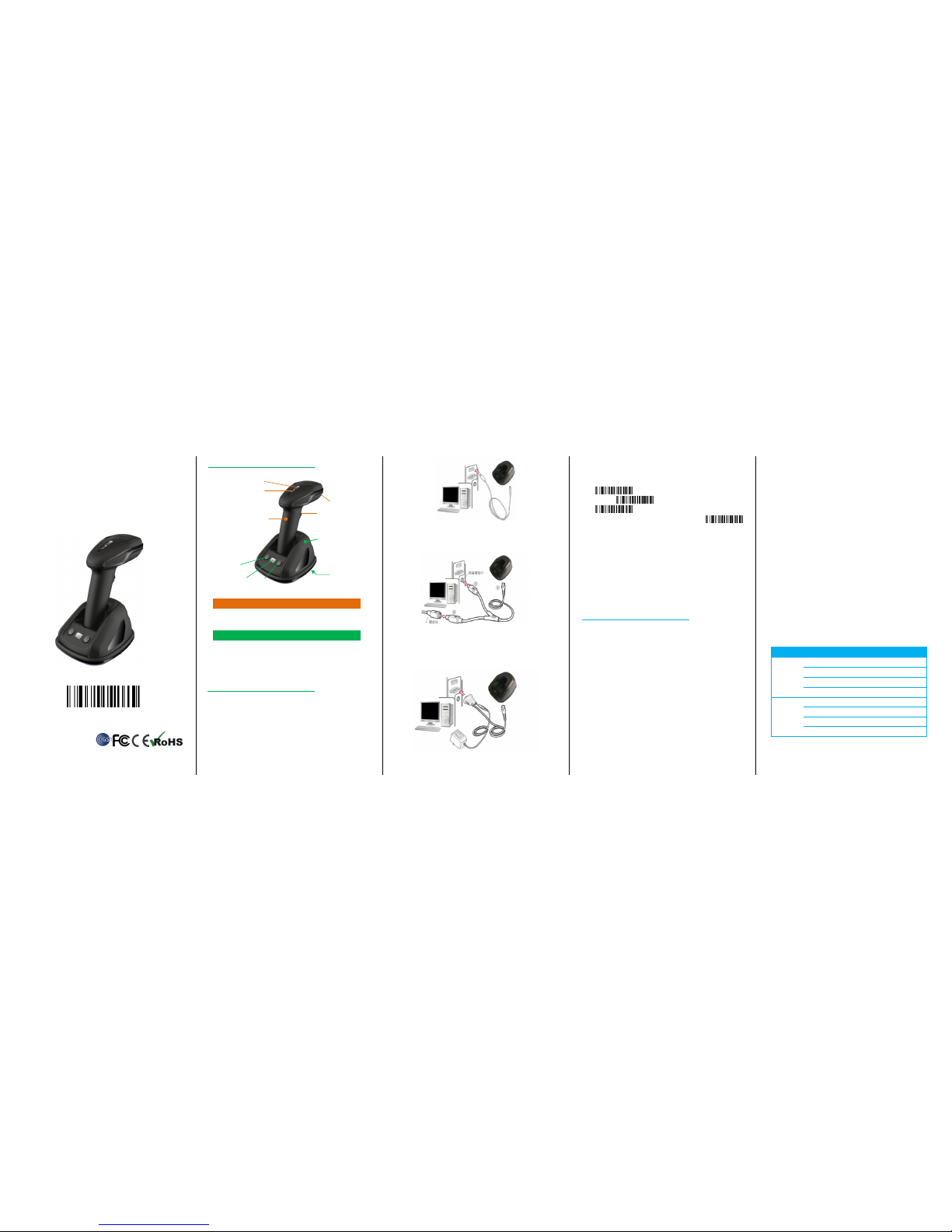
Handset&Cradle
A Handset
①Data Indicator(Front)
②Power Indicator(Back)
③Trigger
④View window of capture
B Cradle, data relay and charging handset
⑤Indicator
⑥Pairing Button
⑦Channel Button
⑧Data & Power Interface
Installation
Step1. Refer to the below pictures, connect the cradleto host (e.g. PC)
with different cables firstly:
USB End: Plug the RJ45 endinto cradle ⑧,and plug the other endto the
host.
USB cable
Keyboard PS/2 End:Plug the RJ45 to c radle⑧,and connect the male
PS/2 end to PC port and the female end with keyboard wire.
PS/2cable
RS232 End:RS232 cable RJ45 side to connect cradle⑧,the other side
to connect to PC. Power port on RS232 c able connect to power
adaptor(DC5V).
RS232cable
Typically,the cradle will identify theinterface type automatically. In
extreme casescradle may need a manuallysetting if the host fails to
identify it. Please trigger the code below for manual setting.
Automatic Identification(Default)
USB
PS/2
RS232
Note: The auto setting of interface type will only be activated when
the pairing is well done. Please refer to the Step2 and Step3 for pairing.
Step 2.Put the handset onto the cradle, then pair the handset and
cradle: Press and hold cradle⑥for about 4 seconds,until the
handsetissued a "beep-beep-beep" sound.
Note:1 cradle can support maximum 100 handsets. The handset cannot
upload data if the handset and cradle were not well paired.
Usage of Scanner
Power On/Power off
Scanner will be power on when the trigger is pulled.When the scanner is
not operated for 30seconds,it will turn off automatically.
Code capture
In the standby mode, pull the trigger to capture code. Make sure
the red aiming line is covering the full code.
Recharging
1, Place the handset onto the cradle to start recharging.
2, Using USB DC adapter or USB ports on PCas the power source, it can
be chargedby MicroUSB cable via interface at the handset bottom.
Note : 1. When the handset is low power, the power
indicator②will beflashinggreen.
2.When th e handset is rechargi ng, the power ind icator keeps
flashing red, an d it turns yellow on when charging finish es.
Built-in Data M emory
In Auto-storing Mode, if the handset is out of contact distance limit
with the cradle,the captured code data will be saved into built-in
handset memory and the data indicator① turns red.The handset will
upload the codedata to the cradle automatically whenthe contact
connection comes back normal.Then the data indicator② turns green.
Multi-Cradles wo rking
In case two or more cradles working in the same room, please set
them to different channels to ensure high upload efficiency as follow.
1. Open a notepad or any text editoron the host to display the channel
number.
2. Press the cradle Channel button⑦ to change the channel number.
3. Put the handset o nto the cradle. Press and hold the cradle
button⑥for about 4 seconds to pair the handset and cradle.
Remark: If two or more cradles working in the same signal channel, it
will slow down upload speed. However, they won’t jam with each other.
Indicator&Button
Scanner Indicator
Indicator
state
Meaning
Power
Indicator
(②Back)
Green
Started normally
Greenflash
Power low,need to recharge
Red flash
Recharging
Yellow
Recharge finished
Data
indicator
(①Front)
Green
All data uploaded
Red
Stored data pending to upload
Red flash
Data storage is full
Yellow flash
Data is uploading
Possibility of upload failures: Cradle disconnected to PC; Exceeding
distance limit; Handset working in Manual Upload Mode (stock check).
①
②
③
⑤ ⑥ ⑦ ④ ⑧
□
A
□
B
Cradle Indicator
Light
Meaning
Green
Flashing: Identifying interface
On: Interface is identified
Red
Flashing:Receiving code data
On:Stored data pending to upload
Cradle Button
Button
Position
(mark)
Function
Pairing
Button⑥
Left
Button
Press and hold it 4seconds to pair
the handset and cradle. A
“Dee-Doo-Dee” means pairing
finishes.
Channel
Button⑦
Right
Button
Settingsignal channel. One press for
one channel No. up.
Settings
Set Defaults
Set Defaults
Notice: The setting to the cradle must be done after the handset is well
paired with cradle.
Information Check
Handset Serial No.
Cradle Serial No
Battery Power
Channel & Handset ID
Suffix Quick Setup
CR(Default)
LF
CR+LF
None
Setting the Data Upload Mode
No Storing Mode: Every code data will be uploaded instantly to the
cradle once they are well captured. In case of unsuccessful upload, the
code data will be ignored and alarm of “Dee-Dee-Dee” will come out.
Auto Storing Mode (Default): The data will be stored in the handset
memory in case of upload failure to cradle. And the data will be
uploaded to cradle once the contact connection come back normal.
Manual Mode: The code data will firstly be stored in the built-in
handset memory once well captured. It can store up to 10,000pcs code
data. The data would be uploaded to cradle in one time once the
Upload Start Code is manually triggered.
During the process of uploading or after upload well finished, if the
Upload Start code is triggered, allcode data stored in handset will be
uploaded again.
Auto Storing(Default)
No Storing
Manual Mode
Upload Start(in Manual Mode)
Remark: In the Manual Mode, all stored code data will be kept
untilmanually erased. Every time the Upload Start code is triggered, all
code datastoredin handset will be uploaded again. To avoid duplicating
upload data, please trigger Erase Storage code to clear handset data.
Erase Storage
Insert Scanner ID before Barcode
In case two or more handsets are connected to the same cradle, the
handset ID can be inserted as prefix to each captured code in o rder to
identify the handset of capturing and uploading the single code.
Start insertinghandset ID
Stop inserting handset ID (Default)
Setting Power of Wireless Communication
High(Default 16dBm)
Middle(8dBm)
Low(0dBm)
Caution: Please check with your local authority and set the power of
wireless communication according to local rules and regulations.
Setting the Volume of Beeper
High(Default)
Middle
Low
Mute
Prefix
Start Transmit Prefix
Stop Transmit Prefix (Default)
Scan Prefix(0~16 Chars, 2Digits/Char; 00~FF; 00*)
Suffix
Suffix(Default)
Do Not Transmit Suffix
Scan Suffix (0~22 chars, 2 Digits/Char; 00~FF; 0D*)
Parameter bar code
0
1
2
3
4
5
6
7
8
9
A
B
C
D
E
F
Finish Setting
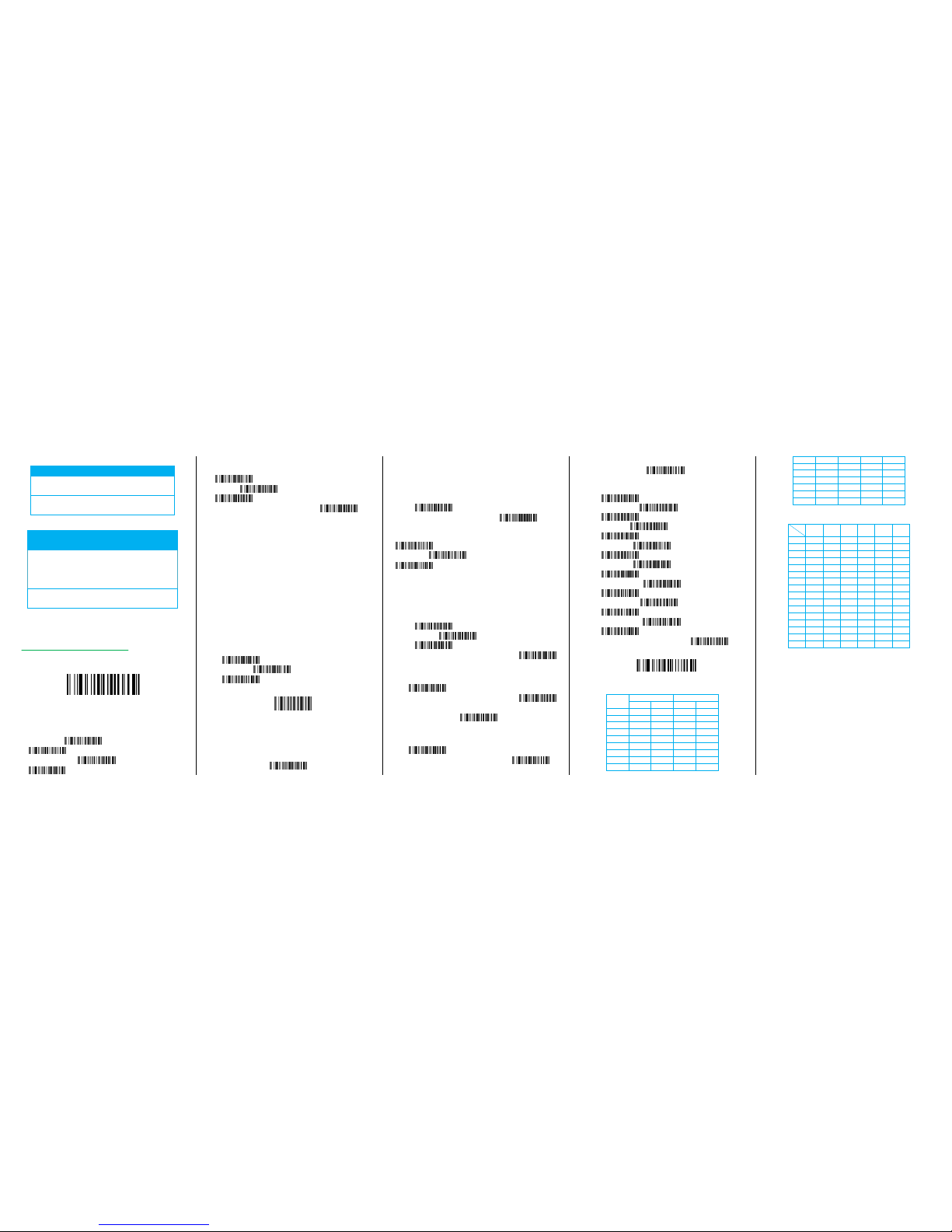
Table 1 Function Keys
H
L
P/S2 keyboard/USB
RS-232
0 1 0
1
0
Null NUL
DLE
1
Up
F1
SOH
DC1
2
Down
F2
STX
DC2
3
Left
F3
ETX
DC3 4 Right
F4
EOT
DC4
5
PgUp
F5
ENQ
NAK
6
PgDn
F6
ACK
SYN
7 F7
BEL
ETB
8
Bs
F8
BS
CAN
9
Tab
F9
HT
EM
A F10
LF
SUB
B
Home
Esc
VT
ESC
C
End
F11
FF
FS D Enter
F12
CR
GS
E
Insert
Ctrl+
SO
RS
F
Delete
Alt+
SI
US
Table 2 Chars
H
L
2 3 4 5 6
7
0
SP 0 @ P `
p
1 ! 1 A Q a q
2 “ 2 B R b r 3 # 3 C S c s 4 $ 4 D T d t
5 % 5 E U e u
6 & 6 F V f v
7 ‘ 7 G W g w
8 ( 8 H X h x 9 ) 9 I Y i
y
A * : J Z j z
B + ; K [ k {
C , < L \ l |
D - = M ] m } E . > N ^ n ~ F / ? O _ o DEL
Example:
Set a Prefix "ab":
1.Find out "a" and "b" in the table 2("61"and "62" )in the ASCII
2. Trigger the barcode "Scan Prefix"and then the "6", "1", "6", "2",
"Finish Setting" one by one.
3.Triggerthe barcode "Transmit Prefix".
 Loading...