

Page 1

- Instruction for light oil burners model:
Cod. 0006080836_200711
en
BTL 0 1 stage
BTL
4 1 stage
BTL 6 1 sta
ge
BTL 10 1 stag
e
Page 2

Page 3

ONE STAGE LIGHT OIL BURNERS
GB - Before using the burner for the rst time please carefully read the chapter “WARNINGS NOTES
FOR THE USER : HOW TO USE THE BURNER SAFELY” in this instruction manual, which is an
integral and essential part of the product. The works on the burner and on the esystem have to be
carried out only by competent people.
- Read carefully the instructions before starting the burner and service it.
- The system electric feeding must be disconnected before starting working on it.
- If the works are not carried out correctly it is possible to cause dangerous accidents.
Statement of Conformity
We hereby declare under our own responsibility, that our “CE” marked products
Series: BTL…;
Description:
domestic and industrial blown air burners red by gas, oil and dual fuel
respect the minimal regulation of the
European Directives:
• 90/396/EEC (G.A.D)
• 92/42/EEC (B.E.D)
• 89/336/EEC (E.M.C. Directive)
• 73/23/EEC (Low Voltage Directive)
• 98/37 EEC (Machinery Directive)
and have been designed and tested in accordance with the European
Standards:
• EN 676 (gas and dual fuel, gas side)
• EN 267 (light oil and dual fuel, oil side)
- EN 60335-1:2001:A1:2004+A11:2004 +A2:2006
- EN 60335-2-102:2006
- EN 50165:1997:A1:2001
- EN 55014-1:2000 + A1:2001+A2:2002
- EN 55014-2:1997 + A1:2001
- EN 50366:2004 + A1:2006
- EN 61000-3-2:2000 + A2:2005
Surveillance accordingly Gas Appliances Directive 90/396/EEC made by:
CE0085 - DVGW
3 / ...
000608....._2006/09
Page 4

ONE STAGE LIGHT OIL BURNERS
WARNING NOTES FOR THE USER
HOW TO USE THE BURNER SAFELY
FOREWORD
These warning notes are aimed at ensuring the safe use of the components of heating systems for civil use and the production of hot water.
They indicate how to act to avoid the essential safety of the components being compromised by incorrect or erroneous installation and by
improper or unreasonable use. The warning notes provided in this guide also seek to make the consumer more aware of safety problems in
general, using necessarily technical but easily understood language. The manufacturer is not liable contractually or extra contractually for any
damage caused by errors in installation and in use, or where there has been any failure to follow the manufacturer’s instructions.
GENERAL WARNING NOTES
• The instruction booklet is an integral and essential part of the product and must be given to the user. Carefully read the warnings in the
booklet as they contain important information regarding safe installation, use and maintenance. Keep the booklet to hand for consultation
when needed.
• Equipment must be installed in accordance with current regulations, with the manufacturer’s instructions and by qualied technicians. By
the term ‘qualied technicians’ is meant persons that are competent in the eld of heating components for civil use and for the production
of hot water and, in particular, assistance centres authorised by the manufacturer. Incorrect installation may cause damage or injury to
persons, animals or things. The manufacturer will not in such cases be liable.
• After removing all the packaging make sure the contents are complete and intact. If in doubt do not use the equipment and return it to the
supplier. The packaging materials (wooden crates, nails, staples, plastic bags, expanded polystyrene, etc.) must not be left within reach of
children as they may be dangerous to them. They should also be collected and disposed on in suitably prepared places so that they do no
pollute the environment.
• Before carrying out any cleaning or maintenance, switch off the equipment at the mains supply, using the system’s switch or shut-off systems.
• If there is any fault or if the equipment is not working properly, de-activate the equipment and do not attempt to repair it or tamper with it
directly. In such case get in touch with only qualied technicians. Any product repairs must only be carried out by EOGB authorised assistance centres using only original spare parts. Failure to act as above may jeopardise the safety of the equipment. To ensure the efciency
and correct working of the equipment, it is essential to have periodic maintenance carried out by qualied technicians following the manufacturer’s instructions.
• If the equipment is sold or transferred to another owner or if the owner moves and leaves the equipment, make sure that the booklet always
goes with the equipment so it can be consulted by the new owner and/or installer.
• For all equipment with optionals or kits (including electrical), only original accessories must be used.
BURNERS
• This equipment must be used only for its expressly stated use: applied to boilers, hot air boilers, ovens or other similar equipment and not
exposed to atmospheric agents. Any other use must be regarded as improper use and hence dangerous.
• The burner must be installed in a suitable room that has ventilation in accordance with current regulations and in any case sufcient to
ensure correct combustion
• Do not obstruct or reduce the size of the burner’ air intake grills or the ventilation openings for the room where a burner or a boiler is installed
or dangerous mixtures of toxic and explosive gases may form.
• Before connecting the burner check that the details on the plate correspond to those of the utility supplies (electricity, gas, light oil or other fuel).
• Do not touch hot parts of the burner. These, normally in the areas near to the ame and any fuel pre-heating system, become hot when the
equipment is working and stay hot for some time after the burner has stopped.
• If it is decided not to use the burner any more, the following actions must be performed by qualied technicians:
a) Switch off the electrical supply by disconnecting the power cable from the master switch.
b) Cut off the fuel supply using the shut-off valve and remove the control wheels from their position.
c) Render harmless any potentially dangerous parts.
Special warning notes
• Check that the person who carried out the installation of the burner xed it securely to the heat generator so that the ame is generated
inside the combustion chamber of the generator itself.
• Before starting up the burner, and at least once a year, have qualied technicians perform the following operations:
a) Set the burner fuel capacity to the power required by the heat generator.
b) Adjust the combustion air ow to obtain combustion yield of at least the minimum set by current regulations.
c) Carry out a check on combustion to ensure the production of noxious or polluting unburnt gases does not exceed limits permitted by
current regulations.
d) Check the adjustment and safety devices are working properly.
e) Check the efciency of the combustion products exhaust duct.
f) Check at the end of the adjustments that all the adjustment devices mechanical securing systems are properly tightened.
g) Make sure that the use and maintenance manual for the burner is in the boiler room.
• If the burner repeatedly stops in lock-out, do not keep trying to manually reset but call a qualied technicians to sort out the problem.
• The running and maintenance of the equipment must only be carried out by qualied technicians, in compliance with current regulations.
4 / ...
000608....._2006/09
Page 5

ONE STAGE LIGHT OIL BURNERS
WARNING NOTES FOR THE USER
HOW TO USE THE BURNER SAFELY
ELECTRICAL SUPPLY
• The equipment is electrically safe only when it is correctly connected to an efcient ground connection carried out in accordance with current
safety regulations. It is necessary to check this essential safety requirement. If in doubt, call for a careful electrical check by a qualied
technicians, since the manufacturer will not be liable for any damage caused by a poor ground connection.
• Have qualied technicians check that the wiring is suitable for the maximum power absorption of the equipment, as indicated in the technical
plate, making sure in particular that the diameter of cables is sufcient for the equipment’s power absorption.
• Adapters, multiple plugs and extension cables may not be used for the equipment’s power supply.
• An ominpolar switch in accordance with current safety regulations is required for the mains supply connection.
• The electrical supply to the burner must have neutral to ground connection. If the ionisation current has control with neutral not to ground
it is essential to make a connection between terminal 2 (neutral) and the ground for the RC circuit.
• The use of any components that use electricity means that certain fundamental rules have to followed, including the following:
- do not touch the equipment with parts of the body that are wet or damp or with damp feet
- do not pull on electrical cables
- do not leave the equipment exposed to atmospheric agents (such as rain or sun etc.) unless there is express provision for this.
- do not allow the equipment to be used by children or inexpert persons.
• The power supply cable for the equipment not must be replaced by the user. If the cable gets damaged, switch off the equipment, and call
only on qualied technicians for its replacement.
• If you decide not to use the equipment for a while it is advisable to switch off the electrical power supply to all components in the system
that use electricity (pumps, burner, etc.).
GAS, LIGHT OIL, OR OTHER FUEL SUPPLIES
General warning notes
• Installation of the burner must be carried out by qualied technicians and in compliance with current law and regulations, since incorrect
installation may cause damage to person, animals or things, for which damage the manufacturer shall not can be held responsible.
• Before installation it is advisable to carry out careful internal cleaning of all tubing for the fuel feed system to remove any residues that
could jeopardise the proper working of the burner.
• For rst start up of the equipment have qualied technicians carry out the following checks:
• If you decide not to use the burner for a while, close the tap or taps that supply the fuel.
Special warning notes when using gas
• Have qualied technicians check the following:
a) that the feed line and the train comply with current law and regulations.
b) that all the gas connections are properly sealed.
• Do not use the gas pipes to ground electrical equipment.
• Do not leave the equipment on when it is not in use and always close the gas tap.
• If the user of is away for some time, close the main gas feed tap to the burner.
• If you smell gas:
a) do not use any electrical switches, the telephone or any other object that could produce a spark;
b) immediately open doors and windows to create a current of air that will purify the room;
c) close the gas taps;
d) ask for the help of qualied technicians.
• Do not block ventilation openings in the room where there is gas equipment or dangerous situations may arise with the build up of toxic
and explosive mixtures.
FLUES FOR HIGH EFFICIENCY BOILERS AND SIMILAR
It should be pointed out that high efciency boilers and similar discharge combustion products (fumes) at relatively low temperatures into the
ue. In the above situation, traditional ues (in terms of their diameter and heat insulation) may be suitable because the signicant cooling
of the combustion products in these permits temperatures to fall even below the condensation point. In a ue that works with condensation
there is soot at the point the exhaust reaches the atmosphere when burning light oil or heavy oil or the presence of condensate water along
the ue itself when gas is being burnt (methane, LPG, etc.). Flues connected to high efciency boilers and similar must therefore be of a size
(section and heat insulation) for the specic use to avoid such problems as those described above.
5 / ...
000608....._2006/09
Page 6
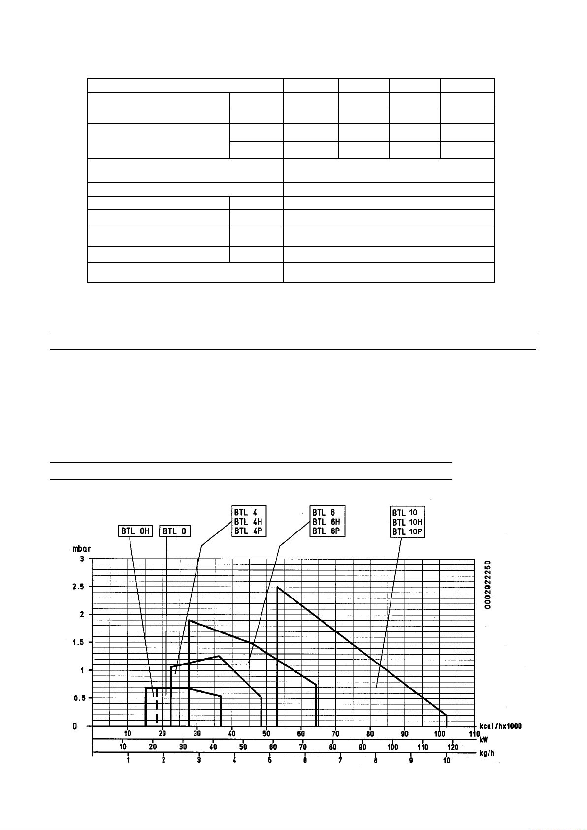
ONE STAGE LIGHT OIL BURNERS
MODEL BTL 0 BTL 4
Burner output
Thermic capacity
Fuel max. viscosity
“Electrical feeding 1 ~ 230V ±10% - 50Hz
Motor kW 0,10
Tranformer
Absobed electrical power *) KW 0,150
Weight kg 12
Operation ON / OFF
*) Total absorption at start with ignition transformer on. de encendido conectado.
STANDARD ACCESSORIES
n° 1 Isolating gasket
n° 1 1/4” x 1/4” x 1200 exible hoses
n° 4 M8 at washer
n° 5 Exagonal nuts M8
min kg/h 1,80 2,20
max kg/h 3,6 4,7
min kW 21,3 26,0
max kW 42,7 56,1
5,5 cst / 20° C
1,5° E / 20° C
40 mA - 15 kV
n° 4 TE M8 x 37 screws
n° 1 M8 x 25 screw
n° 2 1/4” nipples
BTL 6 BTL 10
2,70 5,10
6,3 10,0
31,9 60,2
74,3 118,0
OPERATING RANGE
N° 0002922250
Rev. 15/05/01
6 / ...
000608....._2006/09
Page 7
ONE STAGE LIGHT OIL BURNERS
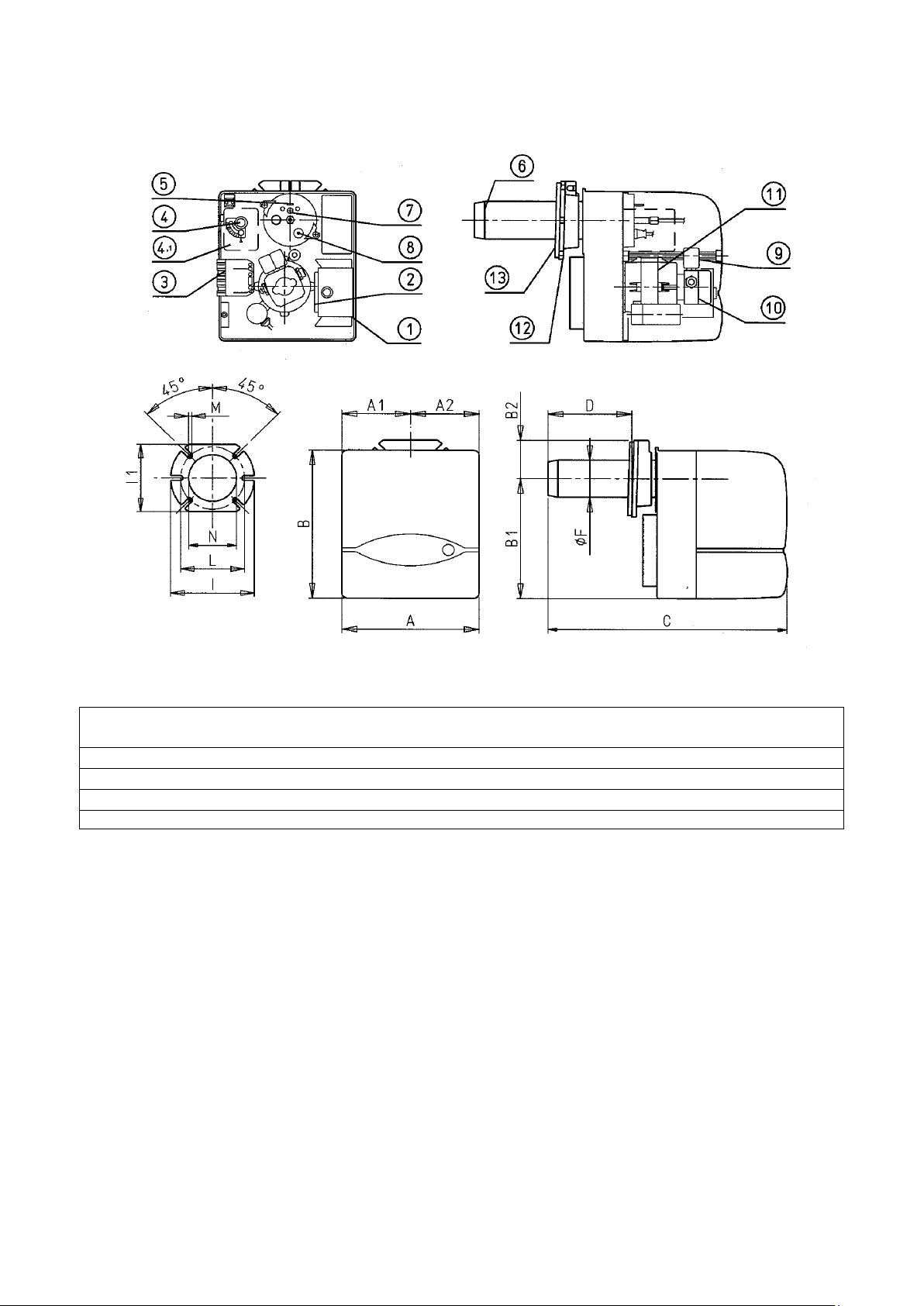
A A1 A2 B B1 B2 C D D F I I1 L L M N
MIN MAX MIN MAX
BTL 0 245 122,5 122,5 270 218,5 70 410 50 105 80 170 140 130 155 M8 85
BTL 4 245 122,5 122,5 270 218,5 70 410 50 105 80 170 140 130 155 M8 85
BTL 6 245 122,5 122,5 270 218,5 70 455 50 150 90 170 140 130 155 M8 95
BTL 10 245 122,5 122,5 270 218,5 70 480 70 158 90 170 140 130 155 M8 95
1) Control box
2) Ignition transformer
3) 7 pole connector
4) Air-damper adjusting screw
5) Reference for disk head positioning
6) Combustion head
7) Disk head adjusting screw
8) Photo-resistance
9) Electrovalve
10) Light-oil pump
11) Motor
12) Burner connection ange
13) Insulating gasket
7 / ...
000608....._2006/09
Page 8
ONE STAGE LIGHT OIL BURNERS
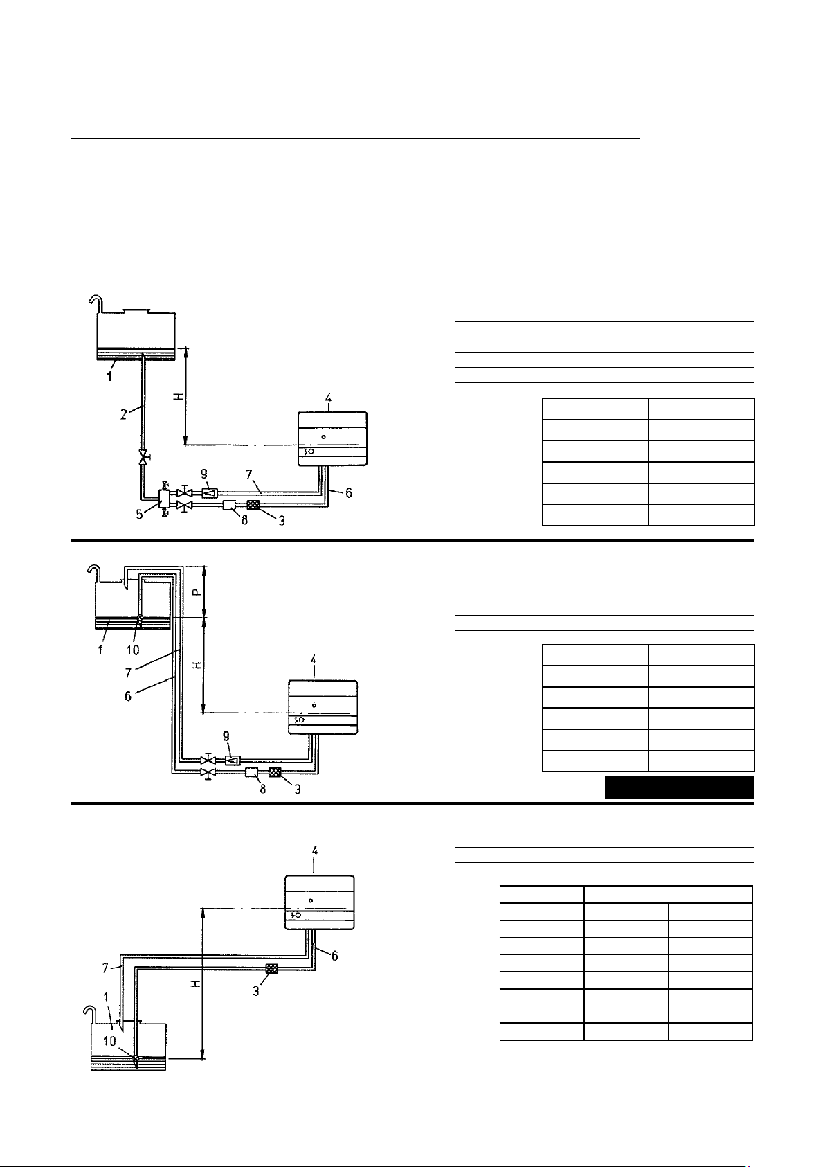
HYDRAULIC CONNECTIONS
N° 0002900860
Rev. 27/07/99
The pipes that connect the tank tothe burner should be in perfect tight condition; we recommend the use of copper or steel pipes
of an adeguate diameter.Fuel gate valves should be fitted at the end of the rigid pipelines.Fit the filter to the suction pipeline
after the gate valve. Connect the flexible fitting to this, which in turn should be connected to the suction of the burner pump.
Connect the flexible fitting to the return pipe after the gate valve, and then connect it ot the pump return. Filter, flexible pipes
and relative connecion nipples are standard burner accessories. The pump is provided with special connection points for the
insertion of control instruments (manometer and vacuumeter).To ensure reliable and silent operating conditions, the vacuum
in suction should not exceed 35 cm Hg equal to 0,46 bar.Maximun suction and return pressure 1,5 bar.
GRAVITY FEED FROM THE BOTTOM OF OIL TANK
1 Oil tank 6 Suction line
2 Feed line 7 Return line
3 Filter 8 Fire valve
4 Burner 9 Non return valve
5 Degasier
H Total meters
meters Ø i. 10 mm.
1 30
2 35
3 40
4 45
GRAVITY FEED OVER THE TOP OF OIL TANK
1 Oil tank 7 Return line
3 Filter 8
4 Burner 9
6 Suction line 10
Fire valve
Non return valve
Foot valve
H Total meters
meters Ø i. 10 mm.
1 30
2 35
3 40
4 45
Quote P = 3,5 m (max)
SUCTION FEED
1 Oil tank 6 Suction line
3 Filter 7
4 Burner 10
H “L. Total meters”
meters Ø i. 10 mm. Ø i. 12 mm.
0,5 26 54
1 24 47
1,5 18 38
2 14 30
N.B. For any missing devices in the
pipping, conform to existing regulations.
H = Measurement between minimum oil level and pump axis
L = Max. legth of suction line, including vertical lifts. For each bend of valve deduct 0,25 m.
Ø i = Internal diameter of pipe
2,5 10 23
3 6 15
3,5 - 7
Return line
Foot valve
8 / ...
000608....._2006/09
Page 9
ONE STAGE LIGHT OIL BURNERS
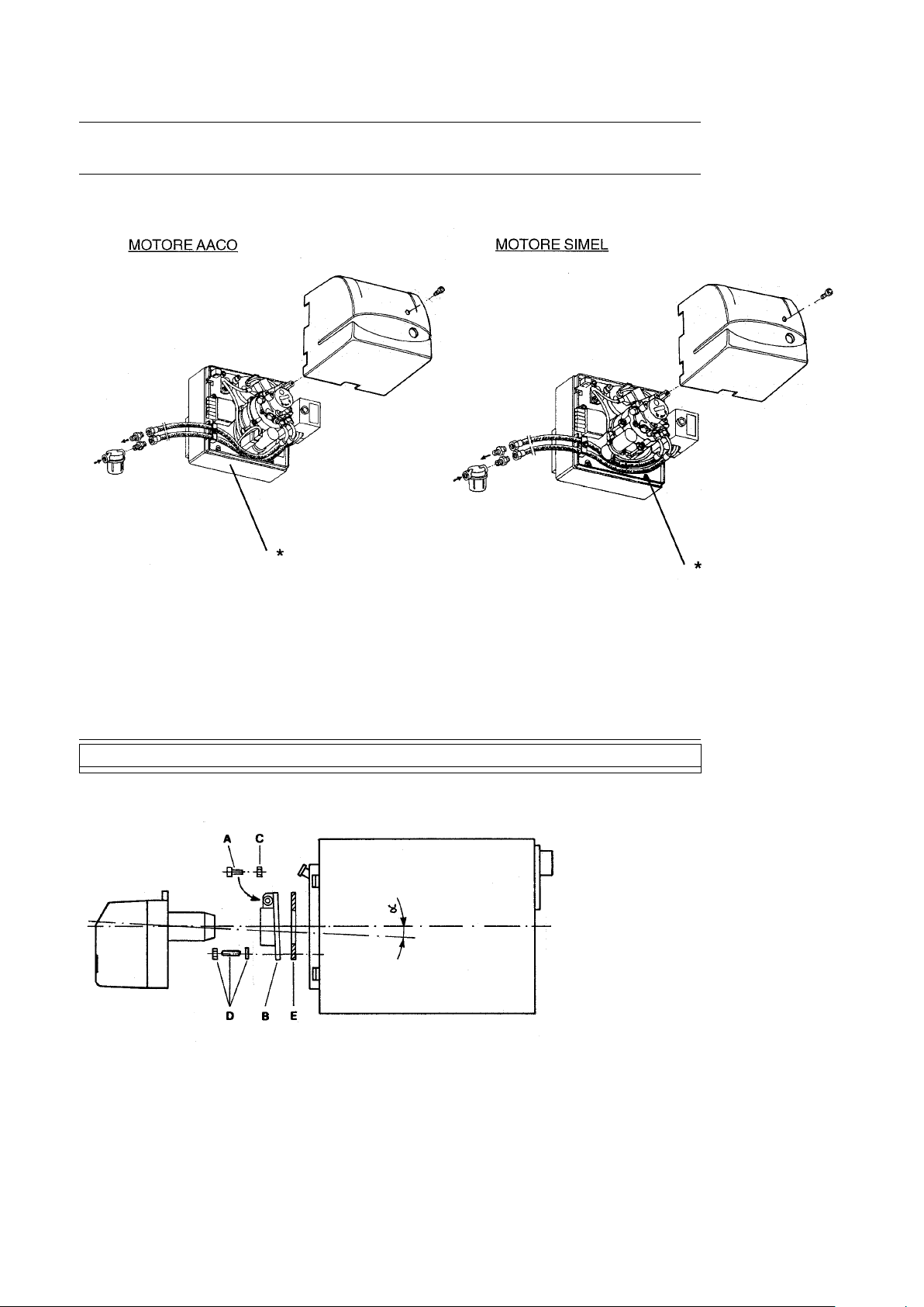
DIAGRAM SHOWING HOW TO PLACE THE FLEXIBLE PIPES
N° 0002933210
Rev. 22/09/00
* The two flexibles hoses shall be positioned as show on the figure for ensuring correct closing of the cover,
they can come out from the lower side or the left side of the burner.
INSTALLING ON BOYLER
WITH SLIDING FLANGE:
- Fasten flange (B) to the boiler with n°4
screws (D) placing the insulation card
(E);
- Insert burner into flange / boiler and
tighten screw (A) with nut (C).
N° 0002932940
Rev. 04/10/99
CAUTION: when attaching the burner to the flange position the combustion head axis as illustrated in the
diagram (angle α).
9 / ...
000608....._2006/09
Page 10
ONE STAGE LIGHT OIL BURNERS
APPLIANCE SPECIFICATIONS
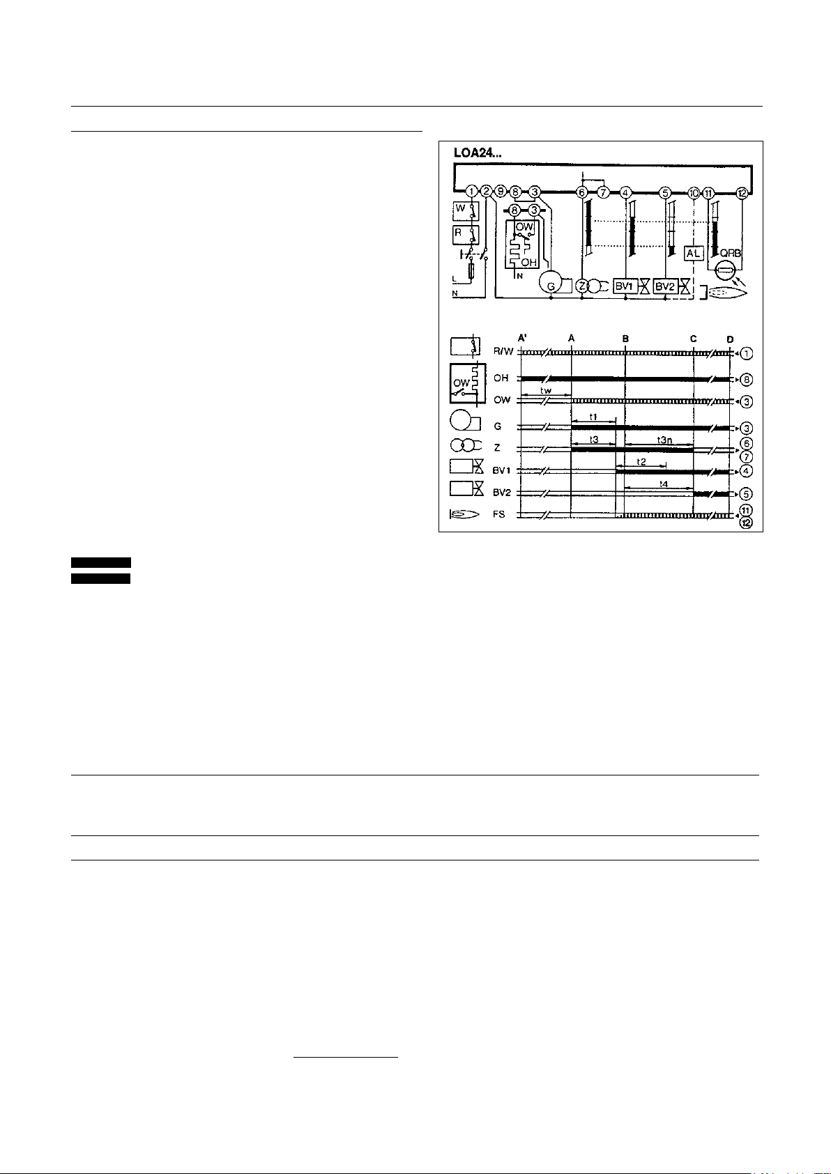
Extraneous light / advanced ignition
During the pre-ventilation and/or pre-starting phase there
shall be no flame signal. Should the signal be present, for
example for advanced ignition due to bad tightness of the
electrovalve, external lighting, short-circuit in the photoresistance or in the connecting cable, a breakdown in the
flame signal amplifier, and so on., when the pre-ventilation
and safety time has elapsed, the control-box brings the
burner to the emergency stop and cuts off fuel inflow even
during the safety time.
No flame
If there is no flame at the end of the safety time, the controlbox stops the burner immediately.
No flame during operation
If there is no flame during operation, the control-box cuts off
fuel and automatically repeats a new starting program: once
the “t4” time has elapsed, the starting program is over.
Every safety stop of less than 1 second switches off voltage
to terminals 3 - 8 - 11: and to terminal 10, it is possible to
provide a remote signal of emergency stop. Resetting of
the control-box is possible after approx. 50 seconds of
emergency stop.
Program Legend
Control-box output signals
Input signals required
A’ Beginning of starting cycle for burners
with light-oil pre-heater “OH”
A Beginning of starting cycle for burner
without light-oil pre-heater
B Flame presence
C Normal operation
tw Light-oil pre-heating time until operation consent
by contact “OW” (minimum thermostat)
t1 Pre-ventilation time
t3 Pre-starting time
t2 Safety time
t3n Post-starting time
t4 Timeintervalbetweenamepresenceand
connection of 2nd valve to terminal 5
D Adjustment stop by “R”
Tension Type Safety at Pre-ventilation Pre-starting Safety Post-starting Time
low voltage time Interval
V ~ t1 t3 t2max t3n BV1-BV2=t4
220/240 LOA 24.171B27 YES 13 s 13 s 10 s 15 s 15 s
PREPARATIONS FOR START UP
Control that the nozzle applied is suitable for the boiler potentiality. The table shows the delivery rates in kg/h of
light oil with respect to the nozzle size and the pump pressure (normally 12 bar). It should be remembered that
1 kg of light oil is equivalent to approximately 10.200 kcal). Make sure that the return pipe in the tank has no
obstructions, e.g. gate valves, closed plugs etc. Any eventual obstruction would cause a breakage in the sealing
surface situated on the pump shaft. Close the main switch and the boiler thermostats in order to start up the
motor and the ignition transformer. Upon completion of the pre-ventilation time, the solenoid valve is activated. the
electrovalve will cut in and expose the photoresistant cell to a source of light until the burner stops (shut down).
When the pipelines have been filled up (and when fuel has come out of the nozzle), stop the burner and put the
photoresistant cell back in its seat.
NOTE: Should it be necessary to purge air, this can be done by loosening the special fitting which the pump is
provided with (see 8930/1). Do not illuminate the photoresistant cell before the electric valve has cut in
because, in this case, the control box will go to “shut down”.
10 / ...
000608....._2006/09
Page 11
ONE STAGE LIGHT OIL BURNERS
IGNITION AND ADJUSTMENT
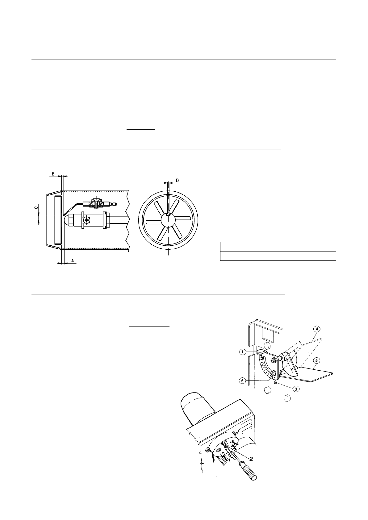
Loosen the xing screw “6” (see 0002933240) and bring the air damper into the position thought to be necessary as a
function of the quantity of fuel to be burnt. Turn the main switch to ON to power the burner and thus ignite it. Correct,
if necessary, combustion air delivery by acting on the intake damper and the position of the deector disk (adjustable
via screw 2, see 0002933230). The burner is, in fact, tted with a special screw to adjust the position of the deector
disk; this device allows for optimisation of combustion by reducing or increasing the air ow between deector disk
and head. It is normally necessary to reduce (undo screw 2) the air ow between deector disk and head when
there is reduced fuel delivery: this passage must be proportionately more open (screw in screw 2) when the burner
is working with a higher fuel delivery rate. After modifying the position of the deector disk it is, usually, necessary to
correct the air damper positions and afterwards check for proper ignition. BTL 0H-4H-6H-10H burners are equipped
with an on-nozzle light oil heater. This device provides better atomisation and thus better combustion.
AIR REGULATION PRINCIPLE DIAGRAM AND DISK-ELECTRODES SETTING
After having installed the nozzle, check the correct
position of the electrodes and disk according to the
following levels. It’s adviseable to check levels after
every intervention on head.
N.B. To prevent damage to the support or
the pre-heater effect nozzle assembly/
disassembly tasks with the aid of a wrench
and counter-wrench.
BTL 0 - 4 3 0 6 2,5
BTL 6 - 10 3 1 6 3
N.B. Ignition can be improved under certain working conditions
by slightly adjusting the position of the electrodes.
COMBUSTION ADJUSTMENT
1 AIR REGISTER OPENING ADJUSTER
- Reference index in position “0” register closed
- Reference index in position “9” register open
N° 0002933351
Rev. 24/07/02
N° 0002933240
Rev. 26/09/00
2 FLAME DISC POSITION
3 AIR REGISTER OPENING ADJUSTER
REFERENCE INDEX
4 AIR DAMPER IN OPEN POSITION (9)
5 AIR DAMPER IN CLOSED POSITION (0)
6 AIR DAMPER FIXING SCREW
0002933230
11 / ...
000608....._2006/09
Page 12
ONE STAGE LIGHT OIL BURNERS
Model
BTL 0 1.00
BTL 4
BTL 6 1,65
BTL 10 2,25 12 9,20 7 6
Nozzle
type
GPH bar kg/h n° tacca n° tacca
0,85 3,50 6,5 3,5
0,75 3,00 5 3
0,60 2,40 4 2
0,50 2,00 3,5 0,5
1,25
1,10 4,70 6 5
1,00 4,20 5,5 4
0,85 3,60 4,5 3,5
0,75 3,10 4 2,5
0,60 2,50 3 1
1,50 6,10 6 5
1,35 5,60 5,5 3,5
1,25 5,00 5 3
1,10 4,70 4,5 3
1,00 4,20 4 2,5
0,85 3,60 3 2
0,75 3,10 3 1
2,00 8,50 7 5
1,75 7,30 6,5 4
1,50 6,10 5 3
1,35 5,60 5 2,5
Pump Burner
12
12
12
Adjustment data
flow rate
4,20 7 5
5,00 6,5 5,5
6,50 6,5 5
3
Air gate
adjustment
Disk position
adjustment
2
NOTE:
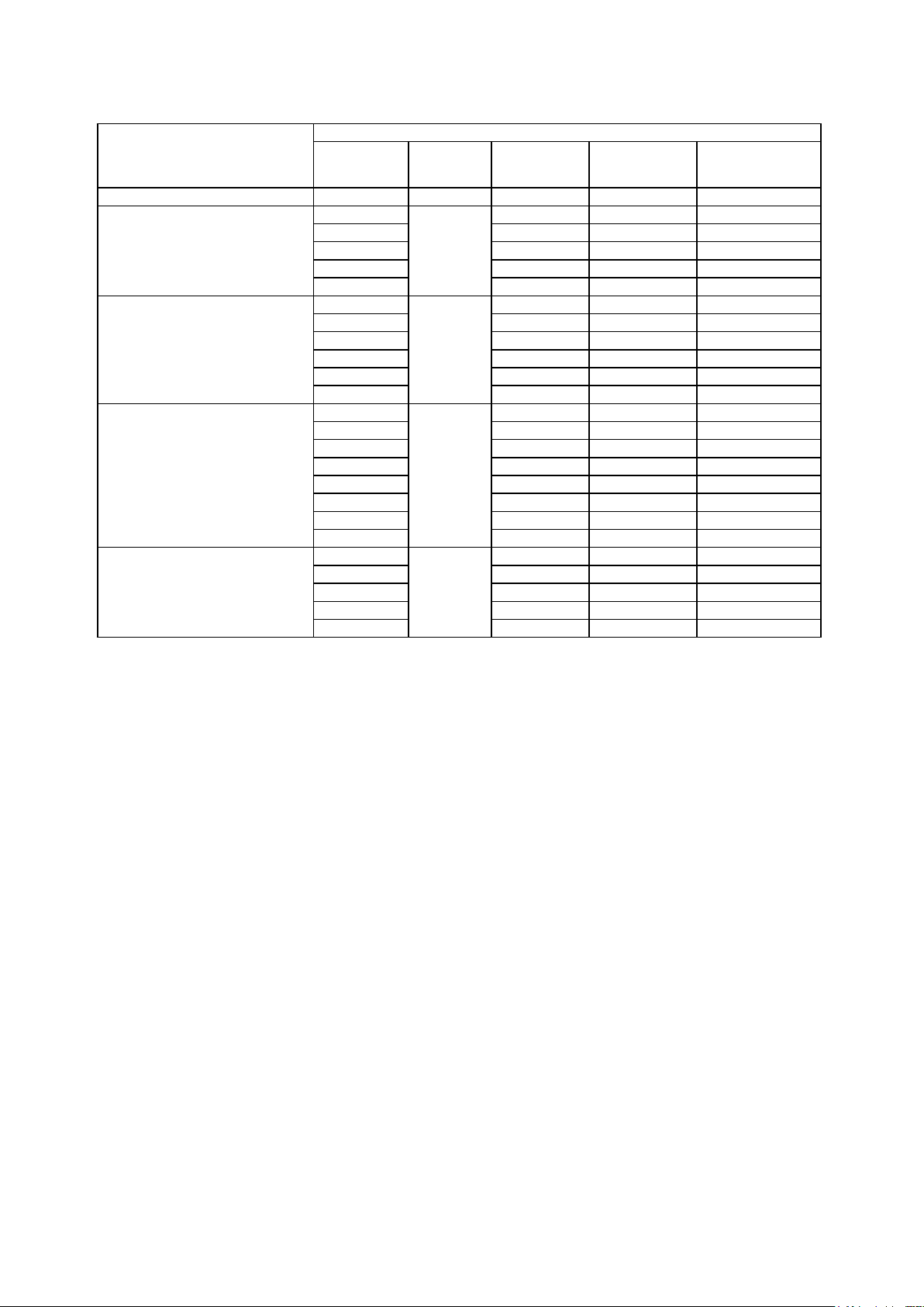
The values repoted on this table are referred at the 12% CO2 at the mean sea level and with 0.1 mbar pressure in the
combustion chambre.
NOTE:
The values indicated in the table are purely indicative; for best burner performance adjustment needs to be made in
accordance with the demands of the particular boiler type.
RECOMMENDED NOZZLES
Delavan type W 45°
Delavan type W 60°
Danfoss type S 45°
12 / ...
000608....._2006/09
Page 13
ONE STAGE LIGHT OIL BURNERS
MAINTENANCE
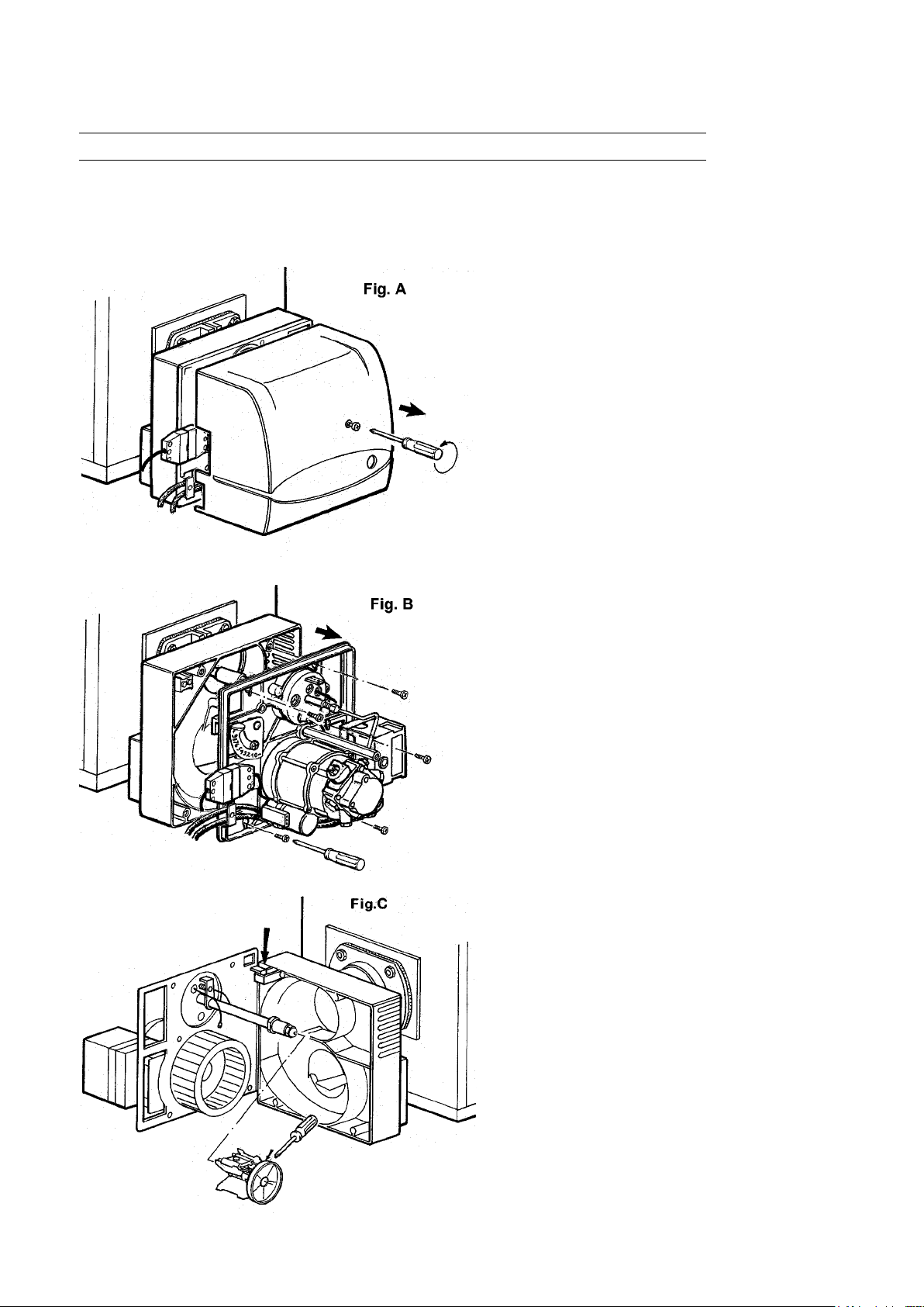
Most components can be inspected by removing the hood. To inspect the head you must disassemble the component-carrying
plate which can be hung on hung on the burner body in two different positions to make work as practical as possible. The motor,
transformer and solenoid valve are connected via a connector while the photo-resistor is push-locked into place.
N° 0002933250
Rev. 26/09/00
1) Undo the lid screw to gain access to the
interior of the burner.
2) Undo the 4 screws of the plate, as indicated,
in order to access nozzle, electrodes and
pre-heater (if tted).
3) The plate must be hung up as illustrated
in g. C.
13 / ...
000608....._2006/09
Page 14

ONE STAGE LIGHT OIL BURNERS
OPERATING ANOMALY
TYPE OF IRREGULARITY PROBABLE CAUSE RIMEDY
The controll-box stops with
ame(redlighton)
The failure is limited to the
ame-controllingdevice.
The control-box stops the
burner with fuel spraying
butnoame(redlighton).
The control-box stops the
burner without spraying
fuel (red light on).
1) Photoresistance is cut off or
dirty with smoke.
2) Boiler fouled
3) Photoresistor circuit failure
4) Dirty disk or mouth.
1) The ignition circuit is broken.
2) The ignition transformer cables have
dried over time.
3) The ignition transformer cables are
not well connected.
4) The ignition transformer is cut off.
5) The electrode faces are not at theright
distance.
6) Electrodes discharge to earth since
they are dirty or with a cracked insulation: also check under the clamps
fastening the insulating materials.
1) There is one phase missing.
2) Insufcient electric motor.
3) Light-oil does not reach the pump.
4) No light-oil inside the tank.
5) Closed gate-valve in suction pipe.
6) Clogged nozzle.
7) Motor rotating in the oppositedirection
as that indicated by the arrow.
1) Clean or replace it.
2) Check all smoke circuits inside the boiler
and the chimney.
3) Replace the control-box.
4) To be cleaned.
1) Check the circuit completely.
2) Replace them.
3) Connect correctly.
4) Replace it.
5) Adjust them to the prescribed position.
6) Clean or, if necessary, replace them.
1) Check the feeder line.
2) Repair or replace it.
3) Check the suction pipe.
4) Fill with fuel.
5) Open it.
6) Disassemble and clean it completely
7) Invert a phase in the input switch.
The burner does not start
Defectiveamewithsparks.
Notwell-shapedame
with smoke and soot.
1) Open contact in (Boiler or room)
thermo-stats or pressure-switches.
2) Short-circuited photo-resistance.
3) There is no voltage because of the an
open contact in the main switch or the
meter overload-release, or no voltage
in the line.
4) The thermo-stats line was not carried out
according to the diagram or thermo-stats
did not close their contacts.
5) Failure inside the control-box.
1) Spraying pressure is too low.
2) Too much combustion air.
3) Insufcient nozzle since it is dirty
or worn out.
4) Water in fuel.
1) Insufcient combustion air.
2) Insufcient nozzie since it is dirty or
worn out.
3) Clogged boiler pipe or chimney.
4) Low spraying pressure.
1) Increase the value or wait for them to close
by natural decrease in temperature or pres-
sure.
2) Replace it.
3) Close the contact of the switches or wait for
voltage to be supplied again.
4) Check thermo-stat connections.
5) Replace it.
1) Bring it to the expected value.
2) Decrease combustion air.
3) Clean or replace it.
4) Discharge it from the tank by using a suitable pump (never use the burner pump to
carry out this operation).
1) Increase combustion air.
2) Clean or replace it.
3) Clean them.
4) Bring it to the prescribed value.
14 / ...
000608....._2006/09
Page 15
ONE STAGE LIGHT OIL BURNERS
SUNTEC AS 47C 1538
DELTA VM 1 LR 24
BT 8930/1
Rev 21/04/94
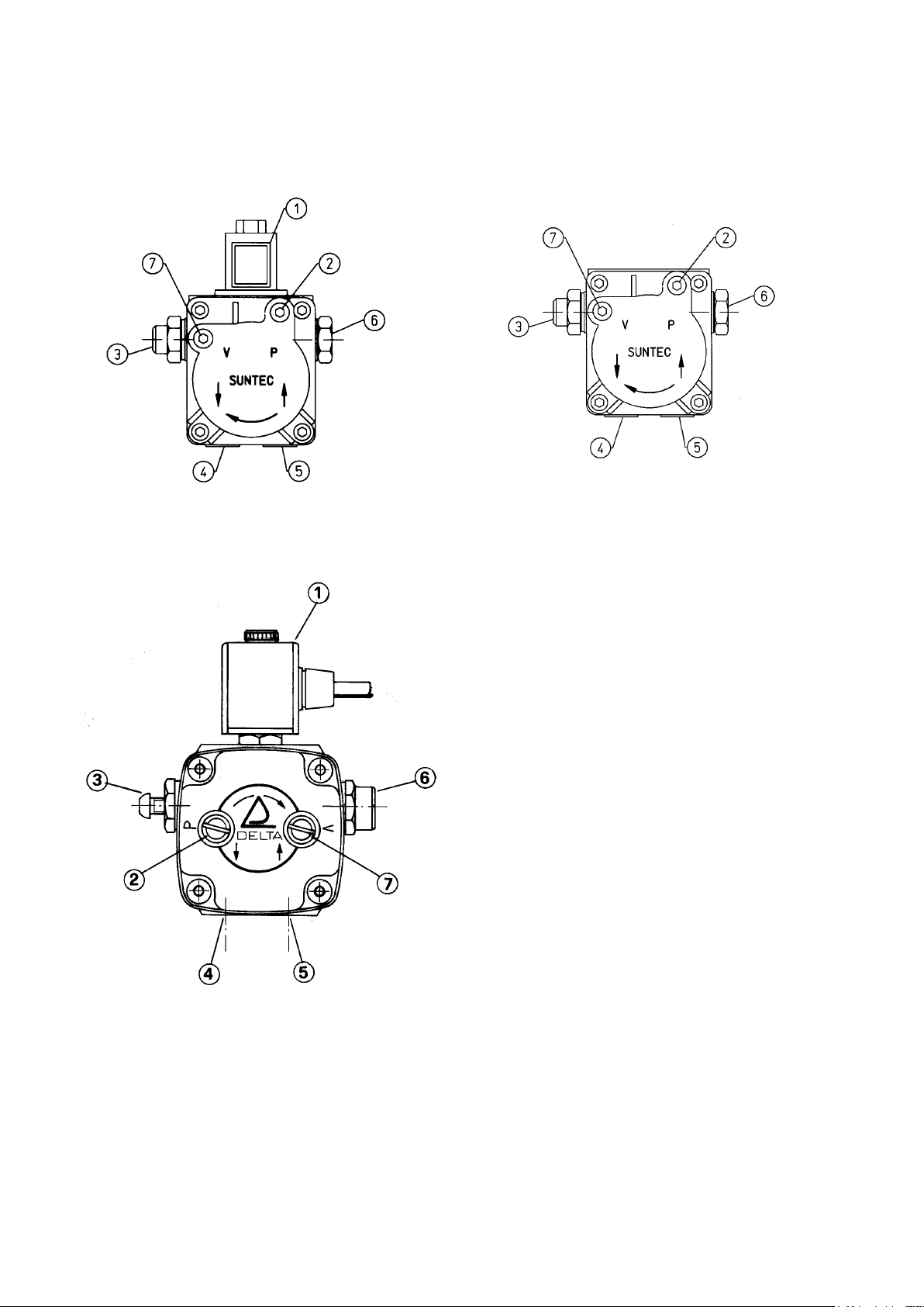
N° 0002900340
Rev 21/04/94
SUNTEC AE 47C 1387
N°0002900910
Rev. 04/05/00
1 ELECTROVALVE (USUALLY CLOSED)
2 PRESSURE TEST POINT AND PURGE POINT
(1/8”)
3 PRESSURE REGULATION SCREW
4 RETURN
5 SUCTION
6 DELIVERY TO NOZZLE
7 VACUUM TEST POINT (1/8”)
N.B. The pump is preset at a 12 bar pressure
15 / ...
000608....._2006/09
Page 16
ONE STAGE LIGHT OIL BURNERS
ELECTRIC CONNECTIONS
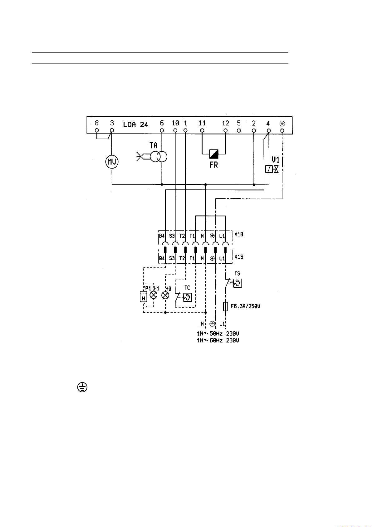
N° BT 2125/2
Rev. 17/07/96
The electrical lines should be at an adeguate distance from hot parts.It is advisable to make all the connections
with exible elecric wire. Conductor’s minimun section 1,5 mm2.
L1 - FASE/PHASE/PHASE
PHASE/FASE
- TERRA/GROUND/TERRE
ERDE/TIERRA
N - NEUTRO/NEUTRAL/NEUTRE
NULLEITER/NEUTRO
H0 -BLOCK LAMP
H1 -OPERATION LIGHT
FR -PHOTO RESISTANCE
TA -IGNITION TRASFORMER
TS -SAFETY THERMOSTAT
TC -BOILER THERMOSTAT
LOA .. -CONTROL BOX
V1 -ELECTROVALVE
MV -FAN MOTOR
P1 -HOUR METER
16 / ...
000608....._2006/09
Page 17

ONE STAGE LIGHT OIL BURNERS
NOZZLE FLOW-RATE TABLE FOR LIGHT OIL
Nozzle
7 8 9 10 11 12 13 14 15 16 17 18 19 20 21
G.P.H.
0,40 1,27 1,36 1,44 1,52 1,59 1,67 1,73 1,80 1,86 1,92 1,98 2,04 2,10 2,15 2,20 0,40
0,50 1,59 1,70 1,80 1,90 1,99 2,08 2,17 2,25 2,33 2,40 2,48 2,55 2,62 2,69 2,75 0,50
0,60 1,91 2,04 2,16 2,28 2,39 2,50 2,60 2,70 2,79 2,88 2,97 3,06 3,14 3,22 3,30 0,60
0,65 2,07 2,21 2,34 2,47 2,59 2,71 2,82 2,92 3,03 3,12 3,22 3,31 3,41 3,49 3,58 0,65
0,75 2,38 2,55 2,70 2,85 2,99 3,12 3,25 3,37 3,49 3,61 3,72 3,82 3,93 4,03 4,13 0,75
0,85 2,70 2,89 3,06 3,23 3,39 3,54 3,68 3,82 3,96 4,09 4,21 4,33 4,45 4,57 4,68 0,85
1,00 3,18 3,40 3,61 3,80 3,99 4,16 4,33 4,50 4,65 4,81 4,96 5,10 5,24 5,37 5,51 1,00
1,10 3,50 3,74 3,97 4,18 4,38 4,58 4,77 4,95 5,12 5,29 5,45 5,61 5,76 5,91 6,06 1,10
1,20 3,82 4,08 4,33 4,56 4,78 5,00 5,20 5,40 5,59 5,77 5,95 6,12 6,29 6,45 6,61 1,20
1,25 3,97 4,25 4,50 4,75 5,00 5,20 5,40 5,60 5,80 6,00 6,20 6,35 6,55 6,70 6,85 1,25
1,35 4,29 4,59 4,87 5,13 5,38 5,62 5,85 6,07 6,28 6,49 6,69 6,88 7,07 7,26 7,44 1,35
1,50 4,77 5,10 5,41 5,70 5,90 6,24 6,50 6,75 6,98 7,21 7,43 7,65 7,86 8,06 8,26 1,50
1,65 5,25 5,61 5,95 6,27 6,58 6,87 7,15 7,42 7,68 7,93 8,18 8,41 8,64 8,87 9,09 1,65
1,75 5,56 5,95 6,31 6,65 6,98 7,29 7,58 7,87 8,15 8,41 8,67 8,92 9,17 9,41 9,64 1,75
2,00 6,30 6,80 7,21 7,60 7,97 8,33 8,67 8,99 9,31 9,61 9,91 10,20 10,48 10,75 11,01 2,00
2,25 7,15 7,65 8,15 8,55 8,97 9,37 9,75 10,12 10,47 10,85 11,15 11,47 11,79 12,09 12,39 2,25
2,50 7,95 8,50 9,01 9,50 9,97 10,41 10,83 11,24 11,64 12,02 12,39 12,75 13,10 13,44 13,77 2,50
3,00 9,54 10,20 10,82 11,40 11,96 12,49 13,00 13,49 13,96 14,02 14,87 15,30 15,72 16,12 16,52 3,00
3,50 11,13 11,90 12,62 13,30 13,95 14,57 15,17 15,74 16,29 16,83 17,34 17,85 18,34 18,81 19,28 3,50
4,00 12,72 13,60 14,42 15,20 15,94 16,65 17,33 17,99 18,62 19,23 19,82 20,40 20,95 21,50 22,03 4,00
4,50 14,31 15,30 16,22 17,10 17,94 18,73 19,50 20,24 20,95 21,63 22,30 22,95 23,57 24,19 24,78 4,50
5,00 15,90 17,00 18,03 19,00 19,93 20,82 21,67 22,48 23,27 24,04 24,78 25,49 26,19 26,87 27,54 5,00
5,50 17,49 18,70 19,83 20,90 21,92 22,90 23,83 24,73 25,60 26,44 27,25 28,04 28,81 29,56 30,29 5,50
6,00 19,00 20,40 21,63 22,80 23,92 24,98 26,00 26,98 27,93 28,84 29,73 30,59 31,43 32,25 33,04 6,00
6,50 20,67 22,10 23,44 23,70 25,91 27,06 28,17 29,23 30,26 31,25 32,21 33,14 34,05 34,94 35,80 6,50
7,00 22,26 23,79 25,24 26,60 27,90 29,14 30,33 31,48 32,58 33,65 34,69 35,69 36,67 37,62 38,55 7,00
7,50 23,85 25,49 27,04 28,50 29,90 31,22 32,50 33,73 34,91 36,05 37,16 38,24 39,29 40,31 41,31 7,50
8,30 26,39 28,21 29,93 31,54 33,08 34,55 35,97 37,32 38,63 39,90 41,13 42,32 43,48 44,61 45,71 8,30
9,50 30,21 32,29 34,25 36,10 37,87 39,55 41,17 42,72 44,22 45,67 47,07 48,44 49,77 51,06 52,32 9,50
10,50 33,39 35,69 37,86 40,06 41,73 43,74 45,41 47,20 48,90 50,50 52,00 53,50 55,00 56,40 57,80 10,50
12,00 38,20 40,80 43,30 45,60 47,80 50,00 52,00 54,00 55,90 57,70 59,50 61,20 62,90 64,50 66,10 12,00
13,80 43,90 46,90 49,80 52,40 55,00 57,50 59,80 62,10 64,20 66,30 68,40 70,40 72,30 74,30 76,00 13,80
15,30 48,60 52,00 55,20 58,10 61,00 63,70 66,30 68,80 71,10 73,60 75,80 78,00 80,20 82,20 84,30 15,30
17,50 55,60 59,50 63,10 66,50 69,80 72,90 75,80 78,70 81,50 84,10 86,70 89,20 91,70 94,10 96,40 17,50
19,50 62,00 66,30 70,30 74,10 77,70 81,20 84,50 87,70 90,80 93,70 96,60 99,40 102,20 104,80 107,40 19,50
21,50 68,40 73,10 77,50 81,70 85,70 89,50 93,20 96,70 100,10 103,40 106,50 109,60 112,60 115,60 118,40 21,50
24,00 76,30 81,60 86,50 91,20 95,70 99,90 104,00 107,90 111,70 115,40 118,90 122,40 125,70 129,00 132,20 24,00
28,00 89,00 95,20 101,00 106,40 111,60 116,60 121,30 125,90 130,30 134,60 138,70 142,80 146,70 150,50 154,20 28,00
30,00 95,40 102,00 108,20 114,00 119,60 124,90 130,00 134,90 139,60 144,20 148,70 153,00 157,20 161,20 165,20 30,00
Pump pressure
Nozzleoutputow-rate
Nozzle
G.P.H.
1 mbar = 10 mmC.A. 100 Pa
1 kW = 860 kcal
light oil density
Special heating oil density
= 0,820 / 0,830 .................................................................................................. PCI = 10150
= 0,900 ........................................................................................... PCI = 9920
Domestic (3,5°E) heating oil density
Heavy oil density (7,9°E)
= 0,970 / 0,980 ..................................................................................PCI = 9650
PCI = Minimum caloric value
= 0,940 ............................................................................PCI = 9700
17 / ...
000608....._2006/09
Page 18

EOGB Energy Products Ltd
5 Howard Road,
Eaton Socon,
St. Neots,
Cambs.
PE19 8ET
Telephone: 08703 899499
Facsimile: 01480 477022
Website: www.eogb.co.uk
19750
6
 Loading...