

Page 1
Page 2

CONTENTS
CONTENTS
CONTENTS
CONTENTS
Notes ........................................................................................................................................................................................... 2
Packaging and Accessories
Chapter
Chapter
Chapter
Chapter 1
Chapter
Chapter
Chapter
Chapter 2
Chapter
Chapter
Chapter
Chapter 3
Chapter
Chapter
Chapter
Chapter 4
Chapter
Chapter
Chapter
Chapter 5
Chapter
Chapter
Chapter
Chapter 6
1
1
1 DVR Instruction .............................................................................................................................................................. 3
2
2
2 DVR Introduction ........................................................................................................................................................... 4
2.1 Front Panel (only for reference) ..................................................................................................................................... 4
2.2 Rear Panel (only for reference) .................................................................................................................................. 5
2.3 Remote controller (only for reference) ......................................................................................................................... 6
3
3
3 Installation
3.1 HDD Installation ................................................................................................................................................................ 7
3.2 Connecting Cameras and Monitor ................................................................................................................................ 7
3.3 Connecting power ............................................................................................................................................................. 7
4
4
4 Basic Operations ........................................................................................................................................................... 7
4.1 System Initialization .......................................................................................................................................................... 7
4.2 Main interface
4.3 Right-click Menu ................................................................................................................................................................ 8
4.4 User Login .......................................................................................................................................................................... 8
4.5 Record file Playback and Backup ................................................................................................................................. 9
4.5.1 Playback .......................................................................................................................................................................... 9
4.5.2 Backup ...........................................................................................................................................................................
4.6 Overview of main menu
4.7 Main Menu ........................................................................................................................................................................ 14
4.7.1 Record .................................................................................................................................................................. 14
4.7.2 Alarm Setup ........................................................................................................................................................ 16
4.7.3 Channel Setup ................................................................................................................................................... 21
4.7.4 Network setup .................................................................................................................................................... 22
4.7.5 User Management
4.7.6 System Setup ..................................................................................................................................................... 26
4.7.7 Display Setup ..................................................................................................................................................... 29
4.7.8 Log Search .......................................................................................................................................................... 30
4.7.9 PTZ Control ......................................................................................................................................................... 31
4.7.10 System Information ......................................................................................................................................... 31
5
5
5 IE and Client Software Login
5.1 IE Plug-in download and installation .......................................................................................................................... 32
5.2 IE Login ............................................................................................................................................................................. 32
5.3 IE interface ....................................................................................................................................................................... 34
5.3.1 Menu Bar ............................................................................................................................................................. 34
5.3.2PTZ Control .......................................................................................................................................................... 41
5.3.3 Video Switch
5.3.4 Playback .............................................................................................................................................................. 41
5.3.5 Snapshot ............................................................................................................................................................. 41
5.4 Client software login ....................................................................................................................................................... 42
6
6
6 Troubleshooting ........................................................................................................................................................... 42
Appendix 1 Domain name application .............................................................................................................................. 44
Appendix 2 Player
Appendix 3 System connection diagram .......................................................................................................................... 49
.......................................................................................................................................................................
....................................................................................................................................................................
.................................................................................................................................................................
...................................................................................................................................................
................................................................................................................................................
.............................................................................................................................................
....................................................................................................................................
.......................................................................................................................................................
2
7
7
11
13
25
32
41
48
16 Channel Embedded Digital Video Recorder User Manual
1
Page 3

Notes
Notes
Notes
Notes
◎ The power supply of this DVR is provided through DC12V adapter, please check the power outlet before
installation and ensure it can meet the requirements of adaptor ;
◎ Do not place the DVR at a place subject to rain or moisture ;
◎ Do not install the DVR at a place subject to violent vibration ;
◎ Do not install the DVR at a place subject to direct sunlight , and be far away from heat and high
temperature environment;
◎ The DVR 's back panel shall be 15cm or more away from other objects or wall , to facilitate fan cooling;
◎ The DVR shall work under temperature, humidity and voltage according to its technical specifications;
◎ The space where DVR installed shall not be stored with corrosive chemicals that may produce volatile
gases , to avoid to affect the DVR ' s life;
◎ The DVR shall be installed in a space without much dust, and the environment should be kept clean and
tidy;
◎ P roper grounding shall be installed during operation;
◎ DVR should be installed to ensure the proper connectivity with other devices .
P
lease
P
lease
P
P lease
lease buy
reading
reading
reading
reading and
buy
harddisk
buy
harddisk
buy harddisk
harddisk from
and
writing
and
writing
and writing
writing requirements.
requirements.
requirements.
requirements.
from
from
from official
official
official
official channel
channel
channel
channel to
to
meet
to
meet
to meet
meet DV
DV
DV
DV R'
R'
R'
R' s
s
long
s
long
s long
long time
time
time
time and
and
much
and
much
and much
much data
data
data
data
Packaging
Packaging
Packaging
Packaging and
F
ollowing
F
ollowing
F
F ollowing
ollowing parts
◎ One IR remote contro ller
◎
A
◎ One piece of p roduct certificat e
◎ One piece of p roduct w arranty card
◎ One piece of p roduct i nstruction
◎ Several
◎ One DC 12 V 5
◎ HDD support (already installed) and a set of mounting screw s .
◎ One piece of CD .
parts
parts
parts are
pair of remote control ler batteries
SATA
and
and
and A
are
are
are included
harddisk data cable s
A
power adapter
A
ccessories
A
ccessories
A ccessories
ccessories
included
included
included in
in
the
in
in the
package:
the
package:
the package:
package:
2
16 Channel Embedded Digital Video Recorder User Manual
Page 4

Chapter
Chapter
Chapter
Chapter 1
1
DVR
1
DVR
1 DVR
DVR Instruction
Instruction
Instruction
Instruction
Real-time
Monitoring
Record
Storage
Backup Support USB flash drive, removable drive, network backup to HDD.
Playback Enable single CH and multiple CH to search playback via DVR or Network.
Network
Operation
Alarm Setting Support HDD & Video input alarm Management and external alarm signal inputs.
Mouse
Operation
PTZ Control Support PTZ camera operations via RS-485.
Analog output, realize monitor functions through monitor.
Support HDD to save real-time record.
Support remote access by authorized users to increase expansibility and security of
system.
Support Mouse operation for flexible system setup.
Table 1-1
T
echnical
T
echnical
T
T
echnical
echnical Specifications
◎ H.264 compression format, but currently16 CH only supports CIF resolution H.264 ;
◎ Linux operation system, graphical interface, supports mouse, front panel and IR remote control operation;
◎ S upport IE browse, real-time network monitor and DVR parameter setting, audio network transmission;
◎ S upport 4 CH audio recording inputs, audio channel bonding, recording, playback, network transmission and
real-time record.
◎ M ultiple recording modes : m anual recording, timing recording, alarm recording(motion or sensor input),
timing & alarm recording( low frame rate recording before alarm, if in motion or sensor input alarm, frame rate
is increased) .
◎ S upports playback of event categories and accurate time; RS-485 port to support PTZ control;
◎ S upport video signal loss alarm; automatic password protection for the sake of illegal operation;
◎ S upport USB flash drive and HDD backup;
◎ S upport 2 SATA HDD, capacity of single one is to 2T;
◎ S upport auto recovery when power off or reset.
Video compression
format
Video output
Specifications
Specifications
Specifications
Main profile H.264
NTSC/PAL : 16 channel BNC input 2 channel BNC out put (1 channel
CVBS, 1 channel SPOT)
16 Channel Embedded Digital Video Recorder User Manual
3
Page 5
Audio 4 channel input/1 channel output / one channel intercom
Display resolution 800*600 60HZ 、 1024*768 60HZ 、 1280*1024 60HZ
Record frame rate PAL: 5 / 6 / 12 / 25 fps NTSC: 5 / 6 / 1 5 / 30 fps
Record resolution CIF/Half-D1/D1 are optional
OSD output VGA/CVBS
Image Quality Lowest, Low, Normal, High, Highest
HDD Support
Video standard PAL/NTSC
Alarm input/output 1 6 channel input/ 4 channel output
Chapter
Chapter
Chapter
Chapter 2
2.1
Front
2.1
Front
2.1
2.1 Front
Front Panel
Panel
Panel
Panel (
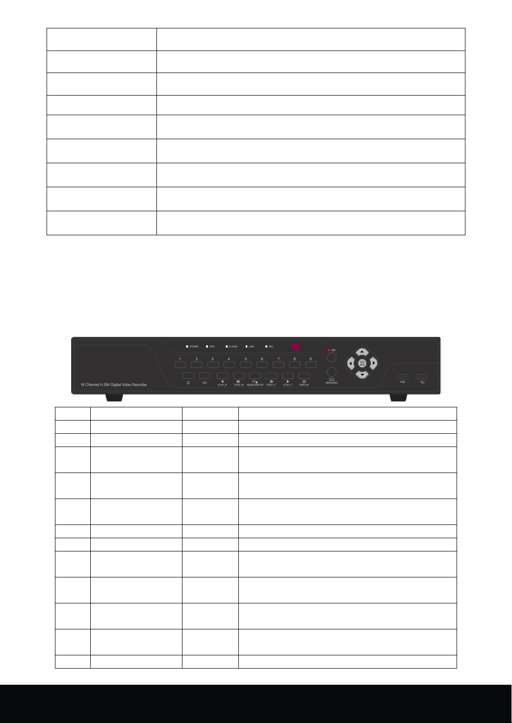
Item Key title/ Indicator Marks Function
1 Power switch O n/ Off
2 Power indicator POWER The "Green" indicator is on as normal power supply
3 HDD indicator HDD T he " Red " indicator means that at least one HDD is
4 Alarm indicator ALARM " Alarm " indicator is on when event trigger s the
5 Network indicator NET Network is connected, " network " indicator is on;
6 Recording Indicator REC REC will flash when start recording
7 IR receiver Receives IR signal from Remote Control
8 N umeric key 1 F or 16 channel, press numeric key 1 to switch to
9 Numeric key 2 For 16 channel, press numeric key 2 to switch to
10 Numeric key 3 For 16 channel, press numeric key 3 to switch to
11 Numeric key 4 For 16 channel, press numeric key 4 to switch to
12 Numeric key 5 For 16 channel, press numeric key 5 to switch to
(
only
(
only
( only
only for
for
reference
for
reference
for reference
reference )
SATA
port
2
2
2 DVR
)
)
)
F unctions of front panel shown as followed:
DVR
DVR
DVR Introduction
Introduction
Introduction
Introduction
mounted successful to be normally used
alarm
network is disconnected, " network " indicator is off
channel 1 when in the menu
channel 2 when in the menu
channel 3 when in the menu
channel 4 when in the menu
4
16 Channel Embedded Digital Video Recorder User Manual
Page 6
channel 5 when in the menu
13 Numeric key 6 For 16 channel, press numeric key 6 to switch to
channel 6 when in the menu
14 Numeric key 7 For 16 channel, press numeric key 7 to switch to
channel 7 when in the menu
15 Numeric key 8 For 16 channel, press numeric key 8 to switch to
channel 8 when in the menu
16 Numeric key 9 For 16 channel, press numeric key 9 to switch to
channel 9 when in the menu
17 Numeric key 0 For 16 channel, press the combination of numeric
key 10+ and 0 to switch to channel 10 when in the
menu
18 Numeric key 10+ For 16 channel, press the combination of numeric
key 10+ and 0-6 to switch to channel 10 -16 when in
the menu
19 PLAY_B F ast reverse
20 STEP_B O ne Frame back forward play
21 SEARCH/STOP Enter record search interface/ Stop playback
22 STEP_F One Frame fast forward play
23 PLAY_F Normal play/F ast forward
24 DISPLAY Display switch / Menu's options switch
25 REC Start /Stop manual record
26 MENU/ESC Enter right click menu/ ESC
27 UP
28 DOWN For the focus transfer of plug-ins in the menu ' s
29 LEFT For the focus transfer of plug-ins in the menu ' s
30 RIGHT For the focus transfer of plug-ins in the menu ' s
31 PTZ Enter PTZ control interface
For the focus transfer of plug-ins in the menu's
interface; move up
interface; move down
interface; move leftwards
interface; move rightwards
2.2
Rear
2.2
Rear
2.2
2.2 Rear
Rear Panel
Panel
Panel
Panel (
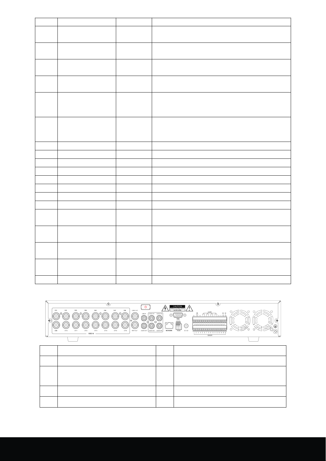
1 CH1-16 video input 6 RS-485
2 Audio output 7 Power port
3 Intercom input 8 Alarm module (sensor input/alarm output
4 Audio input 9 VGA output
5 LAN: Network port 10 CVBS output /SPOT output
(
only
(
only
( only
only for
for
reference
for
reference
for reference
reference )
)
)
)
port) and keyboard port
16 Channel Embedded Digital Video Recorder User Manual
5
Page 7
2.3
Remote
2.3
Remote
2.3
2.3 Remote
Remote controller
controller
controller
controller (
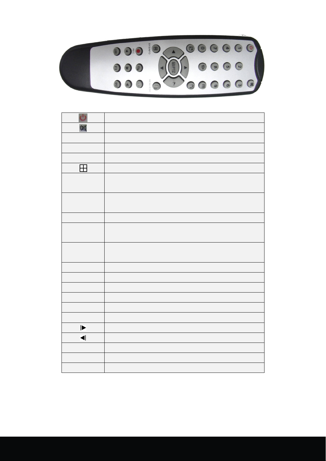
SYSINFO View basic information of system
MENU/ESC P op up right click menu
(
only
for
(
only
( only
only for
1-9 Channel selection: 1 -9
0 Combination of 0 and 10 switch to channel 10
10+ Combination of 0-6 and 10+ switch to 1 0-16 respectively
PTZ Enter PTZ interface/Enter
●
■
reference
for
reference
for reference
reference )
System OFF
Mute
Display switch
For the focus transfer of plug-ins in the menu's interface;
move up
For the focus transfer of plug-ins in the menu ' s interface;
move down
For the focus transfer of plug-ins in the menu ' s interface;
move left wards
For the focus transfer of plug-ins in the menu ' s interface;
move rightwards
M anual record
Stop
Fast forward
)
)
)
Fast reverse
One frame fast forward
One frame back forward
LOG E nter log search interface
F1 Spare key
SPOT SPOT output
6
16 Channel Embedded Digital Video Recorder User Manual
Page 8

Chapter
Chapter
Chapter
Chapter 3
3.1
HDD
3.1
3.1
3.1 HDD
HDD
HDD
HDD
HDD Setup
(1) Open the upper cover of DVR.
(2) Connecting HDD wire and power wire to the mainboard.
(3) Put the upper cover back.
3.2
3.2
3.2
3.2 Connecting
BNC connector ( refer to section 2.2-Rear Panel ) . Ifthe camera is PTZ dome, connect RS485 A & B to the port
of DVR respectively.
Installation
HDD
Installation
HDD Installation
Installation
Notice: D on't take out the HDD while the DVR in operation.
Setup
Setup
Setup :
Connecting
Connecting
Connecting Cameras
C onnect camera cable to video input of DVR, and attach the video output cable from DVR to monitor via
Cameras
Cameras
Cameras and
and
Monitor
and
Monitor
and Monitor
Monitor
3
Installation
3
Installation
3 Installation
Installation
3.3
Connecting
3.3
Connecting
3.3
3.3 Connecting
Connecting power
P lease use the supplied power adapter to connect DVR.
4.1
System
4.1
System
4.1
4.1 System
System Initialization
A fter connecting the power adapter and pressing the power button, the system will be turned on.
4.2
Main
4.2
Main
4.2
4.2 Main
Main interface
system. O nce there are video inputs , the interface will display live images from the channel; if not video
input, interface is defaulted blue. I n the main interface, double-click any channel, the image will be
maximized to full screen, by double-click again, image will come back to multiple display mode; clicking
the right button of mouse then will enter Pop-up Menu, move the cursor to select menu, then click the left
button to enter the selected menu or carry out the functions.
interface
interface
interface
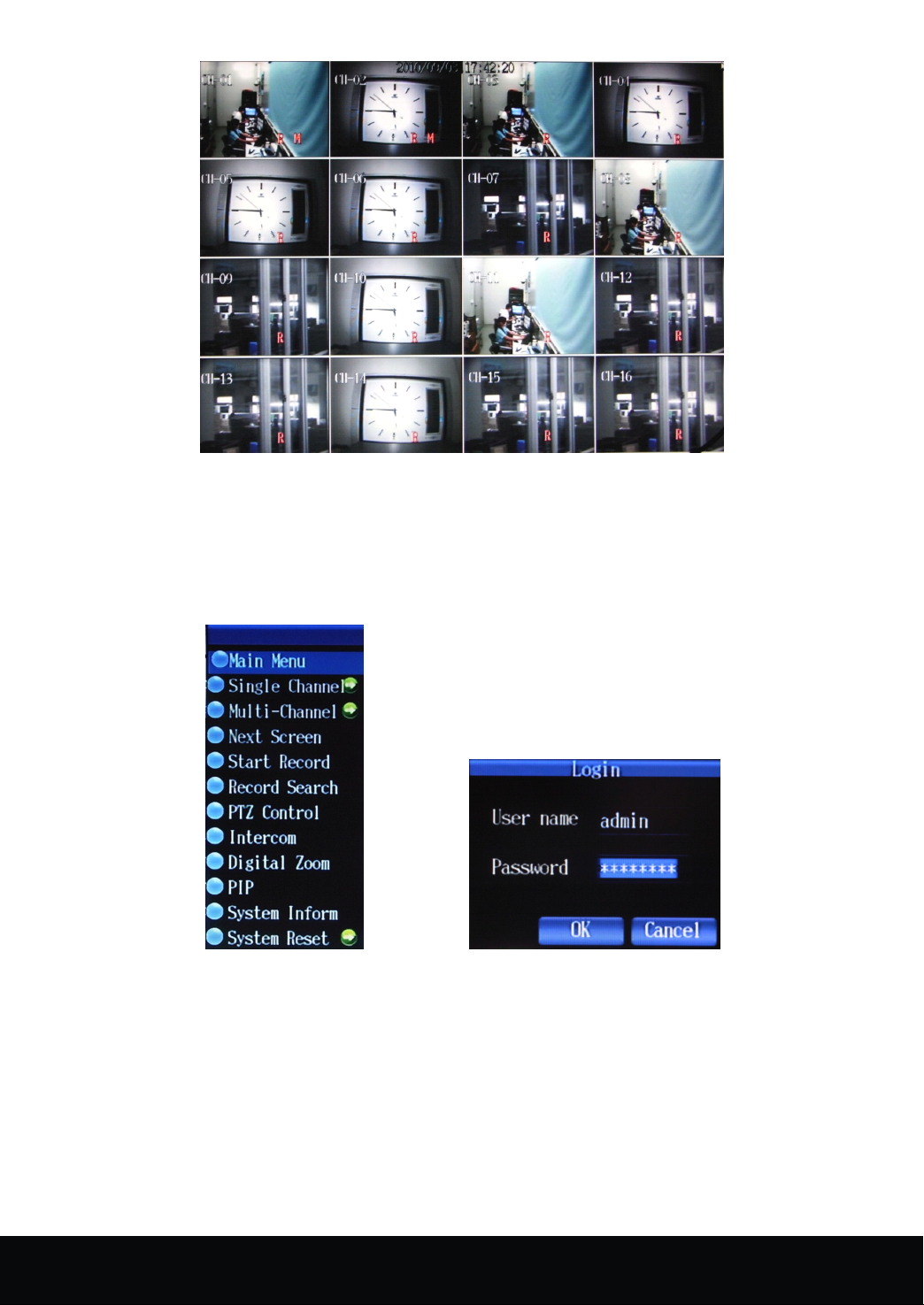
A fter turning on the system will enter main interface. P icture 4-1 is the main interface defaulted by
power
power
power
Initialization
Initialization
Initialization
Chapter
Chapter
Chapter
Chapter 4
4
Basic
4
Basic
4 Basic
Basic Operations
Operations
Operations
Operations
16 Channel Embedded Digital Video Recorder User Manual
7
Page 9
Picture 4- 1
4.3
Right-click
4.3
Right-click
4.3
4.3 Right-click
Right-click Menu
A fter start-up of the system, click right button of mouse in the main interface, through pop-up main menu,
user could perform parameter setting and operate on the main menu, e.g., main menu, video search, PTZ control,
manual record, switch of single channel and multi- channel , shown as picture 4- 2 .
Menu
Menu
Menu
Picture 4- 2 Picture 4- 3
4.4
User
4.4
4.4
4.4 User
the defaulted user name:admin;Password:00000000
8
Login
User
Login
User Login
Login
Click the Menu Key to pop up the information of the User Login,as shown in Image4-2
If any users to be added or passwords to be modified,pls refer to the 'User Management'in Chapter 4.5.5
16 Channel Embedded Digital Video Recorder User Manual
Page 10
4.5
Record
4.5
Record
4.5
4.5 Record
Record file
4.5.1
Playback
4.5.1
Playback
4.5.1
4.5.1 Playback
Playback
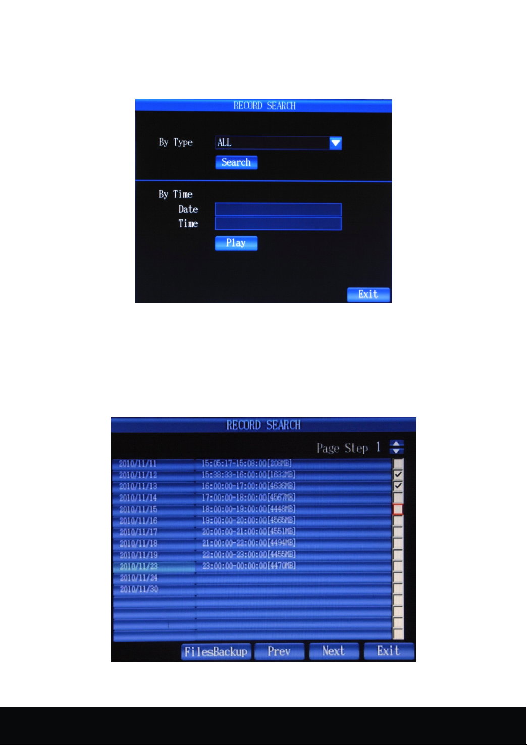
Pls click 'Record Search' in the quick menu(reference to 4.3) to enter the following interface
Two
way for Play back:
1)Search by time, enter the date&time in the 'By Time' Column,then click 'play' button to play the record
file of this time.If no record file in this period,there will be a system note 'File open error'
2)Search By type,enter the record types in the 'By Type' Column,there are five options of the
types:ALL/Manual/Schedule/Alarm/Schedule&Event,then click 'search' button to display the file list as
shown as the following image
file
Playback
file
Playback
file Playback
Playback and
and
Backup
and
Backup
and Backup
Backup
Picture 4- 4
Picture 4- 5
16 Channel Embedded Digital Video Recorder User Manual
9
Page 11
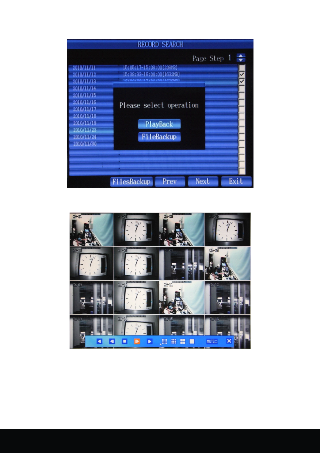
Select one of the files in the list,coming the ollowing note:
Picture 4- 6
Click PlayBack to enter the play format as shown in the following image:
Picture 4- 7
This DVR supports the 16 channel playback simultaneously,or you can also double-click one channel to
operate the single-channel play. Among the function icons of the PLAY Control Bar under the PLAY
window, there is ‘ fast backward,step backward,Stop,step forward,fast forward,16 channel split,9 channel
split,four channel split,single channel display,mute,half-closed,when the archor of the mouse is static for 10
seconds,the PLAY Bar will hide automatically
。
10
16 Channel Embedded Digital Video Recorder User Manual
Page 12
4.5.2
Backup
4.5.2
Backup
4.5.2
4.5.2 Backup
Backup
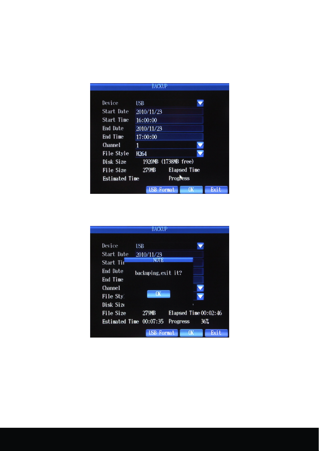
Enter the Record file list interface as shown in Image4-5
File Backup by single file and multiple file:Tick √ in the small column on the right side of the
interface,then click the 'File Backup' at the bottom of the interface.If the 'Single File Backup' is selected,pls
click one of the files in the list as shown in image4-6,then clock 'File Back'to enter the interface as shown
in image4-8
Picture 4- 8
Backuping :
Backup successfully :
Picture 4- 9
16 Channel Embedded Digital Video Recorder User Manual
11
Page 13
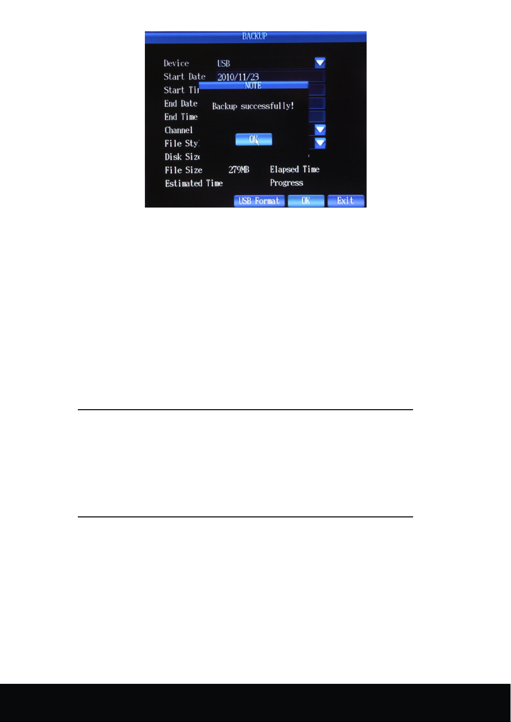
Picture 4- 10
Setting
Setting
Setting
Setting Method:
(1) Set the backup device, file size, channel and some other functions in the recording backup interface
Backup device: Display of the backup device information start
Date and time of the file: setup of start date and time of the backup file
End date and time of the file: setup of end date and time of the backup file
(2) F ormat selection of the back-up files: press the arrow keys to select format of the back-up file. The H264
files is supported. Then press the arrow keys to click the "OK" button, then backup starts. ( T he H264 -format file
could only be opened and played with our client software)
(3) The capacity of external device (and remaining capacity) could be automatically detected and displayed at
the bottom of the window. Meanwhile, the file size and back-up time could be evaluated automatically. The
usage time and backup speed could also been on display.
Method:
Method:
Method:
Notice
12
16 Channel Embedded Digital Video Recorder User Manual
1. The evaluated remaining time(estimated time) may be a bit
different from the actual time.
2 . To identify U disk or USB disk, the back-up device should
be formatted by FAT32 format.
Page 14
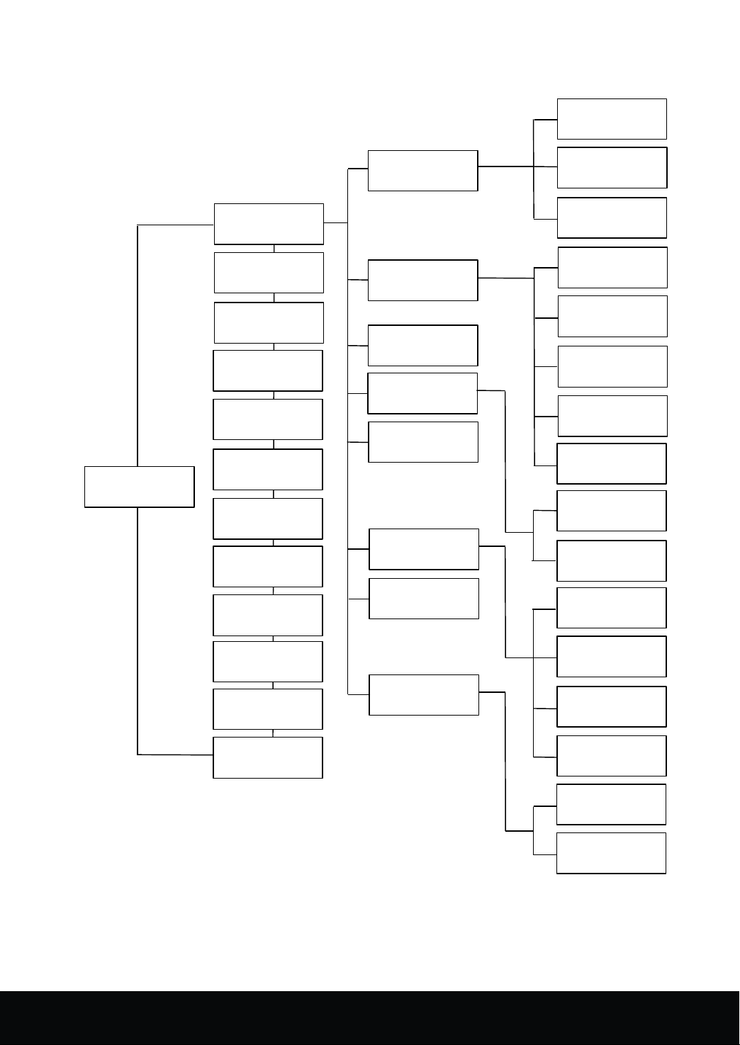
4.
6
Overview
4.
6
Overview
4.
4. 6
6 Overview
Overview of
of
main
of
of main
`
menu
main
menu
main menu
menu
Basic
MENU
Main MENU
Single channel
Multi-channel
Next screen
Start record
Record Search
PTZ Control
Intercom
Record
Alarm
Channel
Network
User
System
Advanced
Plan
Alarm In
Motion
HDD
Password
Video loss
Basic
Advanced
Digital Zoom
PIP
System Inform
System Reset
Display
Log
Basic
Advanced
HDD
Maintain
System
Event
16 Channel Embedded Digital Video Recorder User Manual
13
Page 15
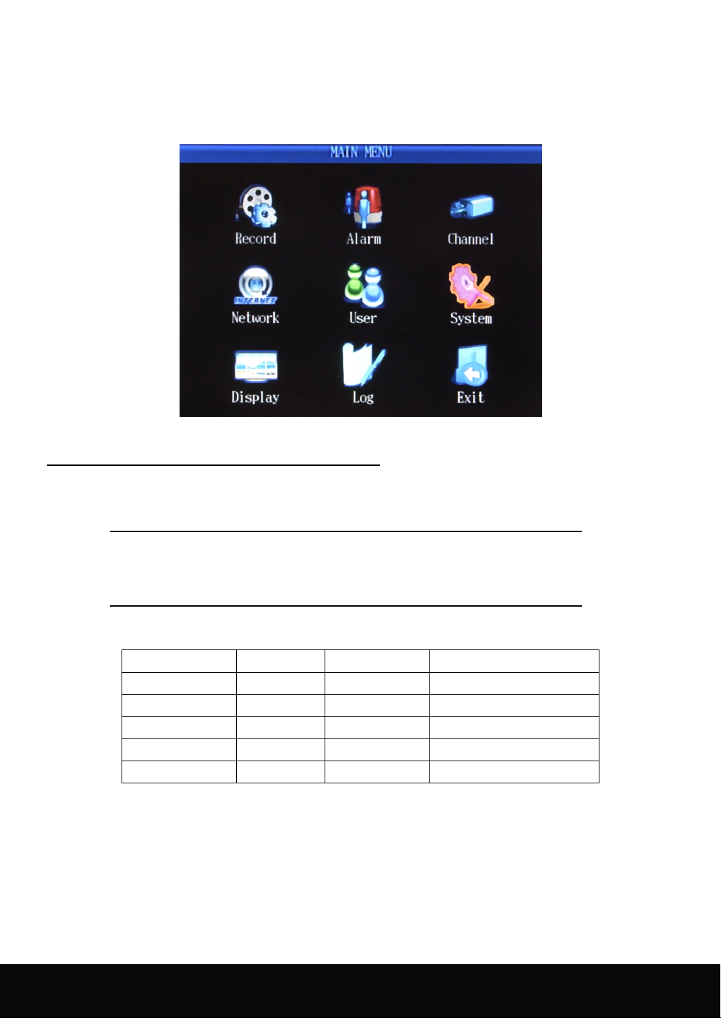
4.
7
Main
4.
7
Main
4.
4. 7
7 Main
Main Menu
could set the following items: Record, Alarm, Channel, Network, User Management , System, Record Backup
and Log Search setting.
4.
7
.1
4.
7
.1
4.
4. 7
7 .1
.1 Record
1
Basic
1
Basic
1
1 ) Basic
Basic setting
Menu
Menu
Menu
I n the main interface, right-click to pop up the menu, click "main menu" (shown as picture 4-3), where
Picture 4- 11
Record
Record
Record
setting
setting
setting
C lick [ Main menu] → [ Record ] to enter [record] menu ( Shown as picture4 - 12 )
T here are options of Resolution, Image Quality, Frame Rate, Audio, Pre- record available in the interface.
Note: [Exit] menu means exit the current interface for returning to
previous menu or main interface.
J ust now the resolution of 16 CH only supports CIF. T here are five grades of IMAGE QUALITY: lowest,
low, normal, high, highest, the comparative result shown as the following table:
Image Quality Resolution Maximum rate C apacity to HDD per hour
lowest CIF 64K 900M
L ow CIF 256K 1.76G
Normal CIF 512K 3.51G
High CIF 768K 7.03G
Highest CIF 1024K 10.55G
a. F rame rate is the number of frame per second, if less than 25 fps, image is not successive, but could save
minor stream and decrease data size. T here are four standards, PAL: 5/6/12/25 frame and NTSC: 5/6/15/30
frame.
b. R ecording is the audio channel relative to video record. Ifwithout input audio source, it doesn't need to set
up this item. T hrough left-click or front panel button to enter the interface of record, pop-up the menu, select
the audio channel with the four options of 1-4 audio channels . Ifchoose [Close], stop recording.
c. Pre-record: when one channel in timing alarm, the number of fps between the beginning of the channel is
triggered by alarm and end of event alarm, two options: 5 frame, 6 frame.
14
16 Channel Embedded Digital Video Recorder User Manual
Page 16

d. C opy to channel: after the setting of parameter of one channel, parameters of other channels are accordance
with the first one channel, and then could use this item to copy the parameters of first one channel to other
channels.
Picture 4- 12
2
Advanced
2
Advanced
2
2 ) Advanced
Advanced setting
T
o get to the ADVANCED SETUP, left click to the interface or via DISPLAY of front panel to other tags.
T here are two options: Override & Time and Date override
S
etting
S
etting
S
S etting
etting method:
Note:
Please
Note:
Please
Note:
Note: Please
Please note
( 1 ) Overwrite: Press the arrow key to select [ Overwrite] , popup dropdown menu with PTZ, and then press
( 2 ) Time and Date Overwrite: Press the arrow key to select [Time and Date Overwrite] , popup dropdown
setting
setting
setting
method:
method:
method:
note
that
PTZ
also
note
that
that PTZ
PTZ
PTZ also
note that
the arrow key to choose YES/NO. If select YES, this will make the new record file will overwrite the
former record file when the capacity of HDD is full. Ifselect NO, the new record file won't be stored in
HDD when the capacity of HDD is full.
menu with PTZ, and then press the arrow key to choose YES/NO. If select YES, this will display time
and date in the video playback, if select NO, the time and date won't be displayed in the video playback.
functioned
also
functioned
also functioned
functioned as
as
Enter.
as
Enter.
as Enter.
Enter.
3
Record
3
Record
3
3 ) Record
Record Plan
Picture 4- 13
Plan
Plan
Plan
16 Channel Embedded Digital Video Recorder User Manual
15
Page 17
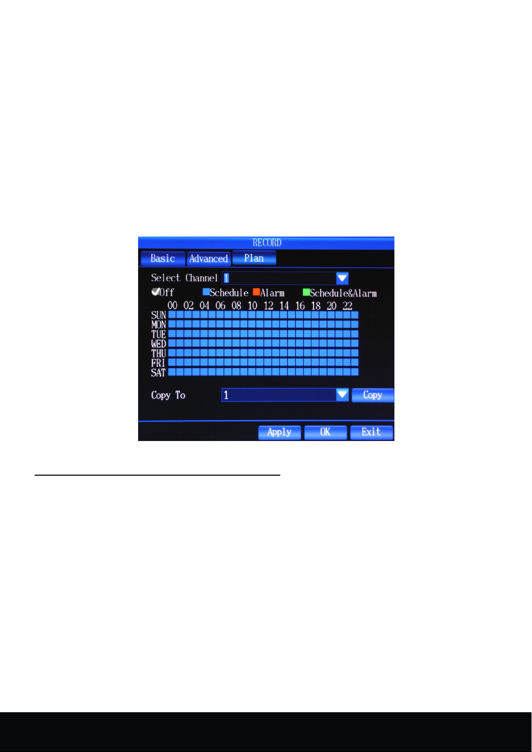
" Record Plan " includes setup of Off, Schedule Record, Alarm Record, and Schedule & Alarm Record.
Record Plan has seven days: Monday, Tuesday, Wednesday, Thursday, Friday, Saturday and Sunday. There are
24 time periods and one hour per time period.
Setting
Setting
Setting
Setting method:
method:
method:
method:
( 1 ) Press the arrow key to "Channel" and enter PTZ to popup the interface.
( 2 ) Move cursor to any options: such as Off, Schedule Record, Alarm Record, and Schedule & Alarm
Record, press PTZ to tick " √ " .
( 3 ) Move cursor to any time options; press the combination of right & left keys and PTZ to select time
area.
( 4 ) Ifapply all settings to other channels , just move cursor to "Copy to"and press PTZ to copy the settings
to one channel or all channels.
( 5 ) Move cursor to "Enter"and PTZ to save above settings.
Picture 4- 14
4.
7.
2
Alarm
4.
7.
2
Alarm
4.
4. 7.
7. 2
2 Alarm
Alarm Setup
1
Alarm
1
Alarm
1
1 ) Alarm
Alarm Input
Setting
Setting
Setting
Setting method
(1)Designated Event Channel: Press the arrow key to select channel , popup dropdown menu with click of PTZ,
and then press the right and left keys to choose channel . Channel 1-16 and all channels are available, while the
default channel is channel 1. A fter selecting channel , enter PTZ to apply the selected channel .
(2)Set the sensor type: Press the arrow key to enter [Sensor Type], popup dropdown menu with click of PTZ, and
then choose "Normal on" or "Normal off", finally, press PTZ to apply the selected options. Normal off refers to
that the external alarm circuit is closed at ordinary times, and open when there is an alarm. Normal on refers to
that the external alarm circuit is open at ordinary times, and closed when there is an alarm.
(3)Alarm record channel setup: Move the cursor to [Record], press PTZ to enter the setting interface, using the
PTZ to choose alarm record channel or choose all channels.
(4) Alarm output setup: The device for the alarm output while set event trigger. T he default is No. In this
interface, press the arrow key to choose action port and PTZ to enter, and press OK to exit.
(5)Buzzer setup:
16
method
method
method :
Setup
Setup
Setup
Input
Input
Input
To
check DVR whether enable beep when set event trigger. Select "Buzzer", press PTZ to open
16 Channel Embedded Digital Video Recorder User Manual
Page 18
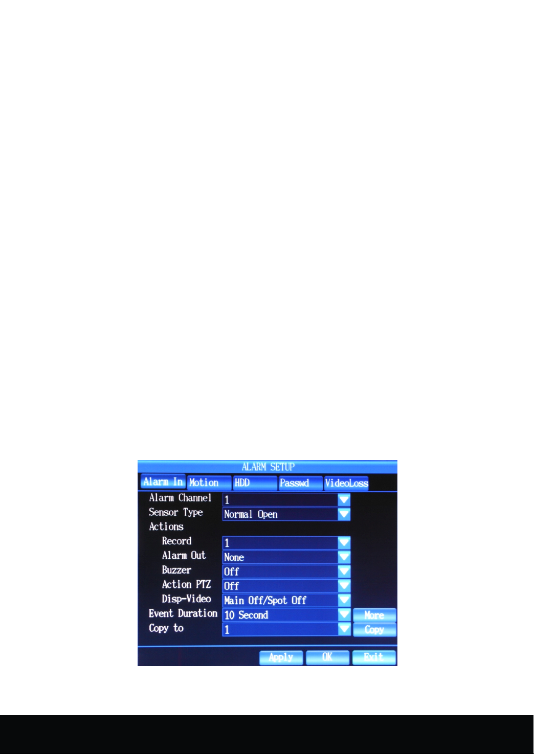
dropdown menu and arrow key to choose ON/OFF. If select ON, the buzzer is activated; if select OFF, the
buzzer is invalid. W hen the event is finished, the buzzer is off automatically.
(6)PTZ Action Setup: When the event is triggered, the preset position will be linkaged. Event is triggered that
PTZ will be moved to front preset position, and move PTZ to back preset position after event is ended.
( a ) Enter PTZ interface, press the arrow key to [Channel], and popup dropdown menu with click of PTZ,
moving arrow key to select channel, finally enter PTZ to apply the selected channels.
( b ) Move cursor to [front preset position], press PTZ to popup menu and arrow key to choose preset
position number and press Enter. Move cursor to [back preset position], press PTZ to popup menu and
arrow key to choose preset position number and press Enter. A t last, press Enter to save parameters.
(7) T he display screen pop-up has two types: Main display switch channel and SPOT switch channel. M ain
display switch channel setup is the channel displays that popup automatically in the display screen of event
trigger setup.
( a ) Enter display screen interface, press arrow key to select main display switch channel, popup the menu
with click of PTZ, and select channel number( options of 1 to 16 channel are available , the default is
OFF. S etting OFF, event trigger won't linkage alarm screen displayed in main display screen
automatically. E nter PTZ to apply the selected channels . W hen event work time is ended, main display
screen will automatically restore pre-split screen of main display screen.
SPOT switch channel setup is the automatic popup channel screen when the setting event is triggered.
( b ) Enter display screen interface, press arrow key to select SPOT switch channel, popup the menu with
click of PTZ, and select channel number( options of 1 to 16 channel are available , the default is OFF.
S etting OFF, event trigger won't linkage alarm screen displayed in SPOT display screen automatically.
E nter PTZ to apply the selected channels .
(8)Event duration means the duration of alarm when the start of event setup.
( a ) Press the arrow key to select [Event Duration], popup dropdown menu with PTZ, and then press the
arrow key to choose working time. T here are following options:
( 3/5/10/20/30/60/120/180/300/600/900/1200 S ) , while the default is 10 seconds.
( b ) F inally, press ON/OFF to apply selected time with PTZ.
2
Motion
2
Motion
2
2 ) Motion
Motion Detection
Picture 4- 15
Detection
Detection
Detection
16 Channel Embedded Digital Video Recorder User Manual
17
Page 19
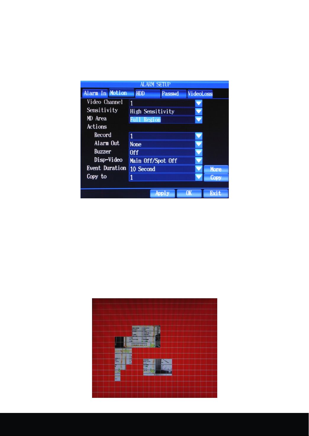
In motion detection, except the setup of sensitivity and MD area, settings of other functions as same as alarm
input, users could follow the former sections. N ext mainly introduce the setting of sensitivity and MD area.
Sensitivity refers to corresponding sensitivity in motion detection when the event record mode is motion
detection or alarm record.
Setting
Setting
Setting
Setting method:
key to choose [Sensitivity].
method:
method:
method:
(1) Press the arrow key to select [Sensitivity], popup dropdown menu with PTZ, and then press the arrow
(2) Enter PTZ to apply the selected sensitivity.
Picture 4- 16
MD
Area
MD
MD
MD Area
detection or alarm record.
choose some part, and enter the interface with the click of PTZ. (Shown as picture 4-17)
Setup
Area
Setup
Area Setup
Setup
MD Area refers to corresponding MD area in motion detection when the event record mode is motion
(1) Press the arrow key to select [MD Area], popup dropdown menu with PTZ, and then press the arrow to
(2) Press the arrow key to select the starting point of motion detection and PTZ to apply the choice, and
move the cursor to choose desired motion area, then enter "ESC"to exit the interface, at last, press
"Enter" to save above settings.
Picture 4- 17
18
16 Channel Embedded Digital Video Recorder User Manual
Page 20
3
HDD
3
3
3 ) HDD
Setting
Setting
Setting
Setting method:
( 1 ) Press the arrow key to select [Alarm Output], enter PTZ to choose action port, and press "Enter" to
( 2 ) Buzzer setup:
( 3 ) Event duration means the duration of alarm when the start of event setup. Press the arrow key to select
( 4 ) S etting the above parameters, press the arrow key to Enter and PTZ to save the parameters.
Error
HDD
Error
HDD Error
Error
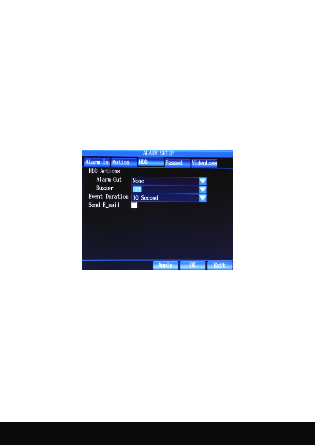
Click DISPLAY to "HDD Error", shown as picture 4- 18.
HDD mistake is that when there is mistake of HDD, DVR will alarm to remind the user.
method:
method:
method:
exit.
To
check DVR whether enable beep when set event trigger. Select "Buzzer", press PTZ
to open dropdown menu and arrow key to choose ON/OFF. If select ON, the buzzer is activated; if
select OFF, the buzzer is invalid. W hen the event is finished, the buzzer is off automatically.
[Event Duration], popup dropdown menu with PTZ, and then press the arrow to choose working time.
T here are following options: ( 3/5/10/20/30/60/120/180/300/600/900/1200 S ) , while the system
default is 10 seconds. F inally, press ON/OFF to apply selected time with PTZ.
Picture 4- 18
4
Password
4
Password
4
4 ) Password
Password Error
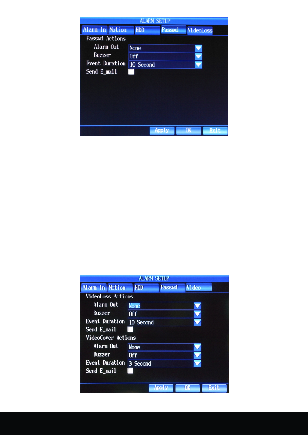
Click DISPLAY to "Password Error ", shown as picture 4- 19.
Password Error means that the current user or other users input wrong password, DVR will alarm to remind
the user.
Error
Error
Error
16 Channel Embedded Digital Video Recorder User Manual
19
Page 21
Picture 4- 19
5
Video
5
5
5 ) Video
Loss
Video
Loss
Video Loss
Loss
Click DISPLAY to "Video Loss", shown as picture 4- 20.
Video Loss: When there is video loss of one channel, DVR will alarm to remind the user.
(1) Press the arrow key to select [Alarm Output], enter PTZ to choose action port, and press "Enter"
to exit.
(2) Buzzer setup:
PTZ to open dropdown menu and arrow key to choose ON/OFF. If select ON, the buzzer is
activated; if select OFF, the buzzer is invalid. W hen the event is finished, the buzzer is off
automatically.
(3) Event duration means the duration of alarm when the start of event setup. Press the arrow key to
select [Event Duration], popup dropdown menu with PTZ, and then press the arrow to choose
working time. T here are following options: ( 3/5/10/20/30/60/120/180/300/600/900/1200 S ) ,
while the system default is 10 seconds. F inally, press ON/OFF to apply selected time with PTZ.
(4) S etting the above parameters, press the arrow key to Enter and PTZ to save the parameters.
To
check DVR whether enable beep when set event trigger. Select "Buzzer", press
Picture 4- 20
20
16 Channel Embedded Digital Video Recorder User Manual
Page 22
4.
7
.3
Channel
4.
7
.3
Channel
4.
4. 7
7 .3
.3 Channel
Channel Setup
Setup
Setup
Setup
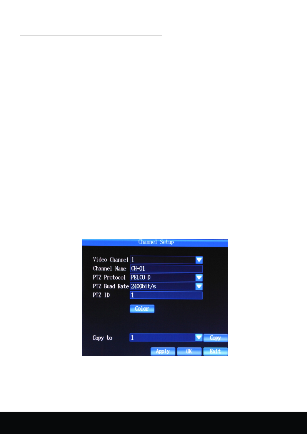
C lick "Main Menu"
options: Channel number, Channel name, PTZ protocol, Baud rate, PTZ address code and color setup.
1. C hannel number: Press the arrow key to select "C hannel number", and press PTZ to apply the
selected channel.
2. C hannel name: Press the arrow key to select"C hannel name"and PTZ to popup the edit
menu( Chinese, English, Numeric, Special character can be input as channel name), if input
numeric or lower case, just use the arrow key to select directly; if input capital letters, user should
press"Caps
edit menu to switch to special character input; if input Chinese, press " En " of edit menu to switch
to Chinese input. 16 characters are supported.
3. PTZ Protocol : This protocol is used to realize the communication with PTZ. I n order to control
PTZ cameras, PTZ should be connected with PTZ port of DVR. P ress the arrow key to select "PTZ
Protocol"and PTZ to popup the dropdown menu, with the click of arrow key to choose appropriate
protocol and enter PTZ to apply the selected protocol.
T here are a number of protocols could be used: PTZ-NULL , LG LPT-A100L , DRX-502A(Demo) ,
PELCO D , NK-97CHE , SAMSUNG SCC-641 , PELCO
Techwin SPD1600/2500 , Wonwoo Eng : SBO-201P1 , Panasonic WV-CS850 .
4. Baud Rate: Press the arrow key to select [Baud Rate], popup dropdown menu, and then press the
arrow key to choose appropriate baud rate, at last, enter PTZ to apply the selected baud rate.
5. PTZ ID: Press the arrow key to select [PTZ ID], popup dropdown menu with click of PTZ, and
then press the arrow key to choose the number, finally enter PTZ to apply the selected number. PTZ IP
ranges from 0-255.
→ "Channel Setup" , the interface is shown as picture
" of edit menu to switch to capital input; if input special character, press the
P
, SJ2819RX , SAMSUNG MRX-1000 ,
4- 21.There are following
" ,. " of
Picture 4- 21
6. Color Setup: Through the setup of color, bright contrast, saturation, hue to set the display of channel.
Press the arrow key to select [Color setup] and PTZ to enter the interface. W ith the click of arrow key to
choose bright, contrast, saturation, hue respectively and use the right and left keys to adjust number.
A fter the adjustment, press ESC to exit the interface, in the end, press the arrow key to select "enter" and
16 Channel Embedded Digital Video Recorder User Manual
21
Page 23
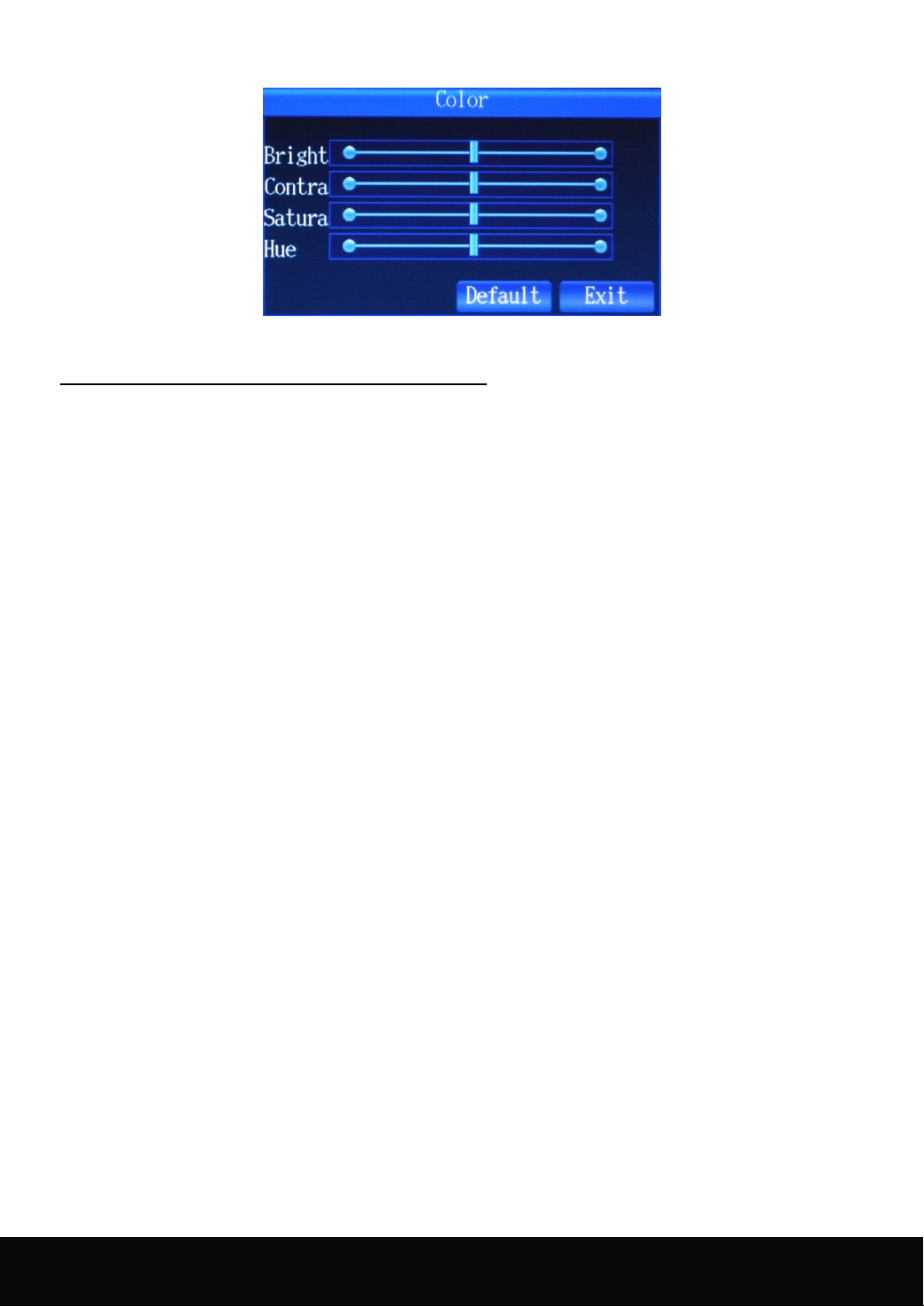
save the settings with the click of PTZ. (shown as picture 4-22)
Picture 4- 22
4.
7
.4
Network
4.
7
.4
Network
4.
4. 7
7 .4
.4 Network
Network setup
Enter [main menu] → [network setup], the interface shown as picture 4- 23 .
1)
Basic
1)
1)
1) Basic
setup
Basic
setup
Basic setup
setup :
Intercom Port.
( 1 ) Connection Mode: Dynamic IP and Static IP
setup
setup
setup
:
:
: Connection Mode, IP address , Netmask , Gateway, NTP Server, HTTP Port, Media Port,
S tatic IP refers to the IP address , Netmask and Gateway assigned manually, this requires that
we're going to apply for an IP address from network administrator. D ynamic IP refers to IP address
assigned by the Dynamic Host via DHCP , you don't need to set
IP,
Gateway or Netmask manually.
S etting method: Press the arrow key to select [Connection mode], popup dropdown menu of PTZ,
and then press the arrow key to choose the connection mode with PTZ key.
( 2 ) IP/
( 3 ) NTP Server address setup: Set the address of time correction server is to realize DVR's time
( 4 ) Port Number Setup: HTTP Port, Media Port and Intercom Port.
Note:
Note:
Note:
Note: When forwarding the ports in the
be forwarded.The defaulted setting are as below:8000,40001,40002,40003.
GATEWAY
O nly when the Static IP is selected as network connection mode, then IP/GA TEWA Y/NETMASK
could be activated.
S etting method: Move down to
Setup of Netmask and Gateway is same way.
synchronization .
Setting method: Press arrow key to select "NTP Server"
enter the address in the interface, finally, click "Enter".
Setting method: Press the arrow key, enter "HTTP Port", and press the PTZ to popup the edit menu,
input port number ( between 1024-65535) , finally , click
Intercom Port is the same way.
/NETMASK Setup
WAN
IP,
and press the PTZ to popup the edit menu, enter the desired
→ enter PTZ → select NTP Server →
"Enter". Setup of Media Port and
setting with the UPNP functon option off,then four ports need to
IP.
22
16 Channel Embedded Digital Video Recorder User Manual
Page 24
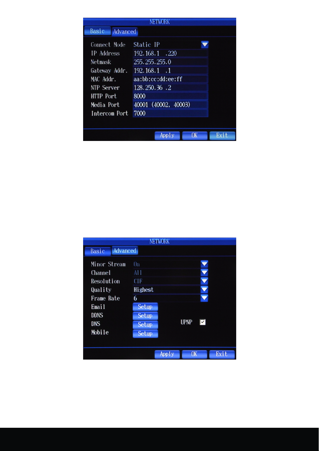
Picture 4- 23
2
Advanced
2
Advanced
2
2 ) Advanced
Advanced Setup
Press "DISPLAY"to switch to "Advanced Setup".
I n this interface, there are following options: code stream, select channel, resolution, quality, frame rate,
Email setup, DDNS setup, DNS setup. I n the former chapters have introduced how to select channel and set
resolution, image quality, frame rate, therefore, the following sections only introduce the setup of code stream,
Email, DDNS , DNS,Mobile port and UPNP.
(1) Minor stream
Can set network transmission resolution,when the network is not connected well,can low the resolution
and frame rate.
Setup
Setup
Setup
Picture 4- 24
(2) Emai l Setup is shown as the picture 4- 25:
a) Press the arrow key to select [ email] and enter the interface with PTZ, and then tick " √ " with the
combination of arrow key & PTZ, open the [Email] menu.
b) I nput SMTP port number, SMTP server, Sender address and password, recipient's address respectively,
at last, press Enter and PTZ to save above settings.
16 Channel Embedded Digital Video Recorder User Manual
23
Page 25
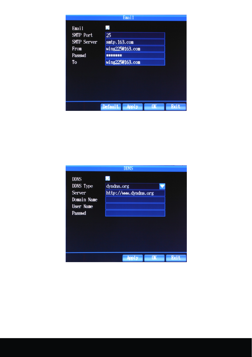
P icture 4- 25
(3) DDNS Setup ( shown as picture 4- 26)
Setting
Setting
Setting
Setting method:
method:
method:
method:
a) Press the arrow key to select [ DDNS] and enter the interface with PTZ, and then tick " √ " with the
combination of arrow key & PTZ, open the [DDNS] menu.
b) Set DDNS type, server address, domain name, user name, password and password confirmation
respectively , at last, press Enter and PTZ to save above settings.
Picture 4- 26
(4) DNS setup as shown in picture 4- 27
Setting
Setting
Setting
Setting Method
a) Press the Arrow keys to select the DNS Setup button, click PTZ button to enter DNS screen, then press the
Arrow keys to select DNS1 or DNS2.
Press PTZ button to enter edit menu, then set the DNS.
b) Click " OK " button after the setup of DNS, then press PTZ button to save the above settings.
24
Method
Method
Method
16 Channel Embedded Digital Video Recorder User Manual
Page 26
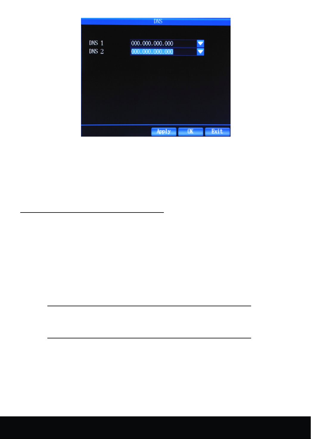
Picture 4- 27
(5) Mobile
Enter the interface,you can setup the mobile port .
(6) UPNP
When the UPNP function is on (UPNP function on the router end is also on of the router setting), then
the DVR will reflect the port and IP into the router automatically.
4.
7
.5
User
4.
7
.5
4.
4. 7
7 .5
.5 User
Enter "Main Menu" → "User Management", the menu screen as shown in picture 4- 28
User Manage is referred as the adding, modifying and deleting of users in addition with the setup of users'
grades.
Setting
Setting
Setting
Setting Method:
(1) Press Arrow keys to click Add button, then press PTZ button, set the name, password and grades of the added
user.
(2) Click OK button after adding the new users, press PTZ button to save the set parameters.
(3)If one of the users is to be edited or deleted, press the Arrow Keys to select this user, then press PTZ key to set
the user as the selected status. Move the cursor to the User-delete button or edit button, press PTZ button to
delete or edit users.
Management
User
Management
User Management
Management
Method:
Method:
Method:
Notice In the user management interface, you could only add 15 users at
most.
16 Channel Embedded Digital Video Recorder User Manual
25
Page 27
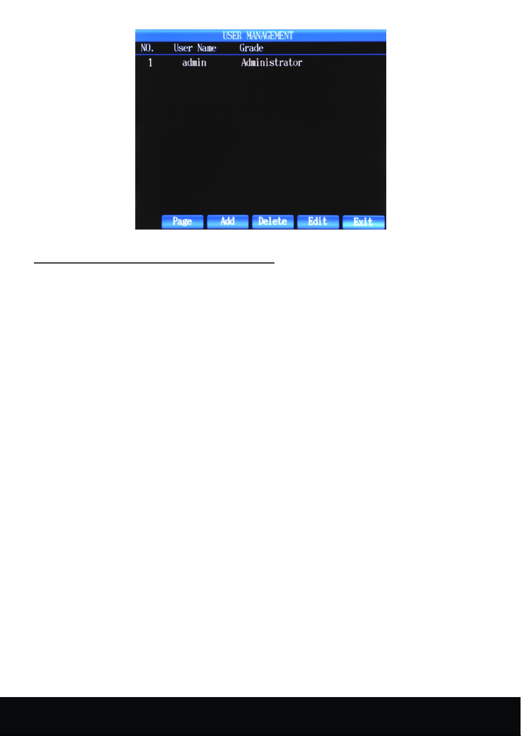
Picture 4- 28
4.
7
.6
System
4.
7
.6
System
4.
4. 7
7 .6
.6 System
System Setup
Click "Main Menu" → "System Setup" to enter System Setup menu interface as shown in Picture 4- 29
1
Basic
1
Basic
1
1 ) Basic
Basic Setup
Setting
Setting
Setting
Setting Method:
the drop-down menu, then press the Arrow Key to select the appropriate format, press PTZ button to apply the
selected format.
drop-down menu, then press the Arrow Key to select the appropriate Time Zone, press PTZ button to apply the
selected time zone. (At present, this function is not available)
the drop-down menu, then press the Arrow Key plus PTZ button to set the date, press Enter button on the edit
menu to apply the selected date.
up the drop-down menu, then press the Arrow Key plus PTZ button to set the time, press Enter button on the edit
menu to apply the selected time.
(At present, this function is not available in remote control )
Method:
Method:
Method:
( 1 ) System Date Format: YYYY/MM/DD,DD/MM/YYYY,MM/DD/YYYY
Setting Method: press the Arrow Key to select the System Date Format Column, press PTZ button to pop up
( 2 ) Time Zone
Setting Method: P ress the Arrow Key to select the Time Zone Column, press PTZ Button to pop up the
( 3 ) System Date Setup
Setting Method : P ress the Arrow Key to select the System Date Setup Column, press PTZ Button to pop up
( 4 ) System Time Setup
Setting Method : P ress the Arrow Key to select the System Time Setup Column, press PTZ Button to pop
( 5 ) Device ID:
W hen using special keyboard or IR remote control to dominate several DVRs, the machine ID is needed.
Setup
Setup
Setup
Setup
Setup
Setup
Setting
Setting
Setting
Setting Method
press the Arrow Key plus PTZ key to set the ID, press the "Enter" key to apply the selected ID. The range of
Device ID is 0-255.
26
Method
Method
Method :
Press the Arrow Key to select Machine ID Column, press PTZ button to pop up the drop-down menu, then
:
:
:
16 Channel Embedded Digital Video Recorder User Manual
Page 28
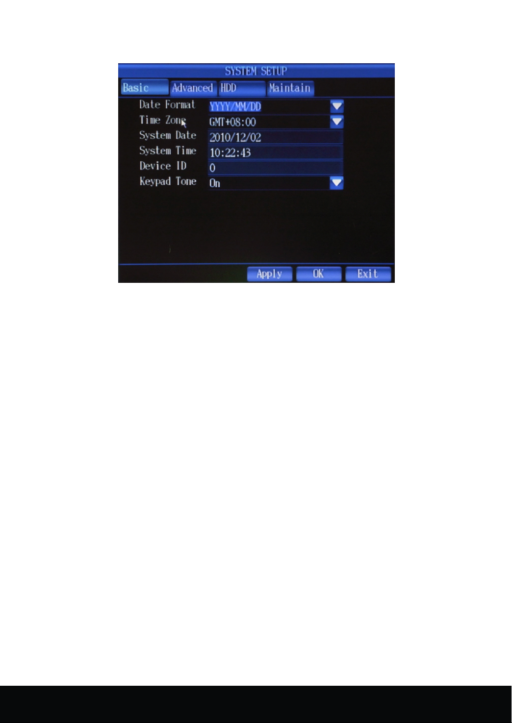
After the setting of the parameters, press the Arrow Key to click OK button, then press PTZ button to save
the above settings.
Picture 4- 29
2)
Advanced
2)
Advanced
2)
2) Advanced
Advanced Setup
Press DISPLAY key to switch into the interface of Advanced Setup.
Advanced Setup Interface indicates three functions: System Language, Format Selection, Auto lock
(1) System Language: set the system display language
Setting Method : press the Arrow Keys to select system language column, press PTZ key to pop up the
drop-down menu, then press the Arrow Keys to select the system display language, press PTZ button to apply
the selected language. The system support s the following languages: Simplified Chinese, Traditional Chinese,
English, Korean and so on.
(2) Format Selection: NTSC and
Setting Method : press the Arrow Keys to select format column, press PTZ key to pop up the drop-down
menu, then press the Arrow Keys to select the format, press PTZ key to apply the selected format.
(3) Auto lock: the system would be automatically locked when having no operation of system function during a
particular period. (At present, this function is not available)
Setting
Setting
Setting
Setting Method:
P ress the Arrow Keys to select auto lock column, press PTZ key to pop up the drop-down menu, and then
press the Arrow Keys to select the intervals. The intervals are optional ( 0/1/3/5/10/30/ ) minutes, the default
setting is 0 minute.
Method:
Method:
Method:
Setup
Setup
Setup
PAL
16 Channel Embedded Digital Video Recorder User Manual
27
Page 29
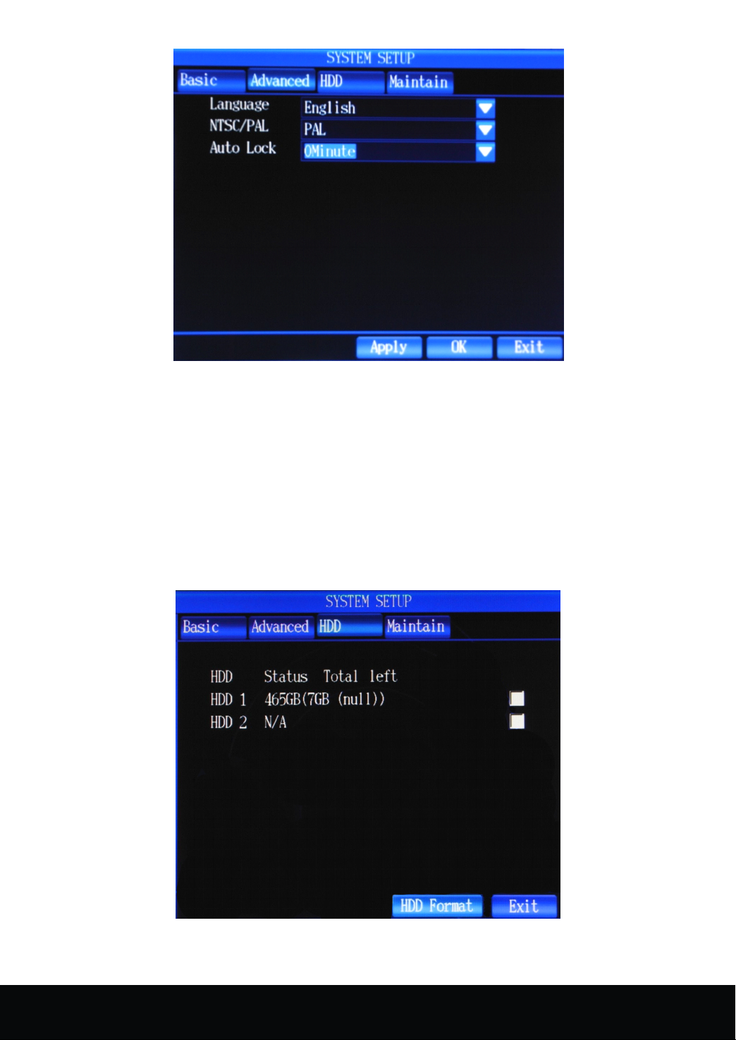
Picture 4- 30
3)
Hard
disk
3)
Hard
3)
3) Hard
Hard disk
Press DISPLAY key to switch to the Hard Disk manage ment interface.
Hard disk management interface mainly displays hard disk information (Hard disk Status, total capacity and
remaining capacity) and the operation of hard disk formatting.
Hard
Disk
Hard
Disk
Hard
Hard Disk
Disk Formatting
Setting
Setting
Setting
Setting Method:
Press the Arrow Keys to select hard disk format and PTZ key to tick √ , p ress the Arrow Keys to click the
hard disk format button, then press PTZ key to execute the formatting.
management
disk
management
disk management
management
Formatting
Formatting
Formatting
Method:
Method:
Method:
4)
System
4)
System
4)
4) System
System Maintain
28
Picture 4- 31
Maintain
Maintain
Maintain
16 Channel Embedded Digital Video Recorder User Manual
Page 30
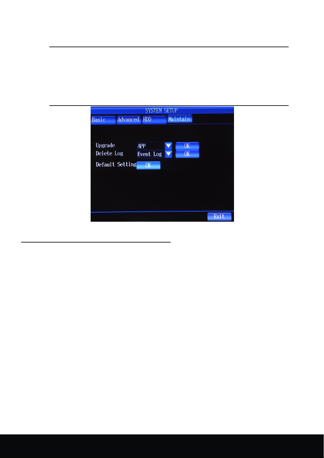
Press DISPLAY key switching to the system maintain interface as shown in Picture 4- 32
The system maintain interface mainly deal with the updating of DVR. Upgrade indicates: System BIOS, System
Image, and System
Note
APP.
1 ) The power supply should not be interrupted when updating; y ou could also
not restart the machine during this period; o r the machine can not start.
2) The lower left of the screen would appear "Upgrading Successfully" after
the successful upgrade. Then you can restart the machine.
3) Unplugging and plugging the USB disk is forbidden during the updating
process, or the device could not continue updating or start.
Picture 4- 32
4.
7
.7
Display
4.
7
.7
Display
4.
4. 7
7 .7
.7 Display
Display Setup
Click "Main Menu " → "Display Setup " to enter Display Setup menu interface as shown in Picture 4- 33
The display setup interface mainly indicates: Main display switching interval (Main Interval), SPOT switching
interval(Spot Interval),video loss ignore(Camera Loss),display resolution.
(1) Main display switching interval (Main Interval) is referred as the setup of the interval between the switching
of the main displaying screen.
Setting
Setting
Setting
Setting Method:
PTZ key to pop up the drop-down menu, finally, press the PTZ key to apply the selected intervals. T he optional
numerical value indicates (1/2/3/5 second etc. ), the default value is 2 seconds.
(2) SPOT Switching Interval (Spot Interval) is referred as setup of the interval between the switching of the
SPOT displaying screen.
Setting
Setting
Setting
Setting Method
drop -down menu, press the Arrow Keys to select the intervals, then press PTZ key to apply the selected intervals.
The optional numerical value indicates (1/2/3/5 second etc. ), the default value is 2 seconds.
(3) Video Loss Ignoring ( Camera Loss ) is referred as the skipping of the channel without video signal input.
Setting
Setting
Setting
Setting Method
key to pop up the drop-down menu, press the arrow key to select on/off, press PTZ key to apply the selected
settings. If the setting is on, then the channel without video input will be skipped. While the setting is off, all the
channels will be displayed whether any video input or not.
Method:
Method:
Method: press the Arrow Keys to select main display switching interval (Main Interval) column, press
Method
Method
Method :
Press the Arrow Keys to select SPOT switching interval(Spot Interval) column, press PTZ key to pop up the
Method
Method
Method :
Setup
Setup
Setup
:
:
:
:
:
: P ress the Arrow keys to select video loss ignoring ( Camera Loss ) column, then press PTZ
16 Channel Embedded Digital Video Recorder User Manual
29
Page 31
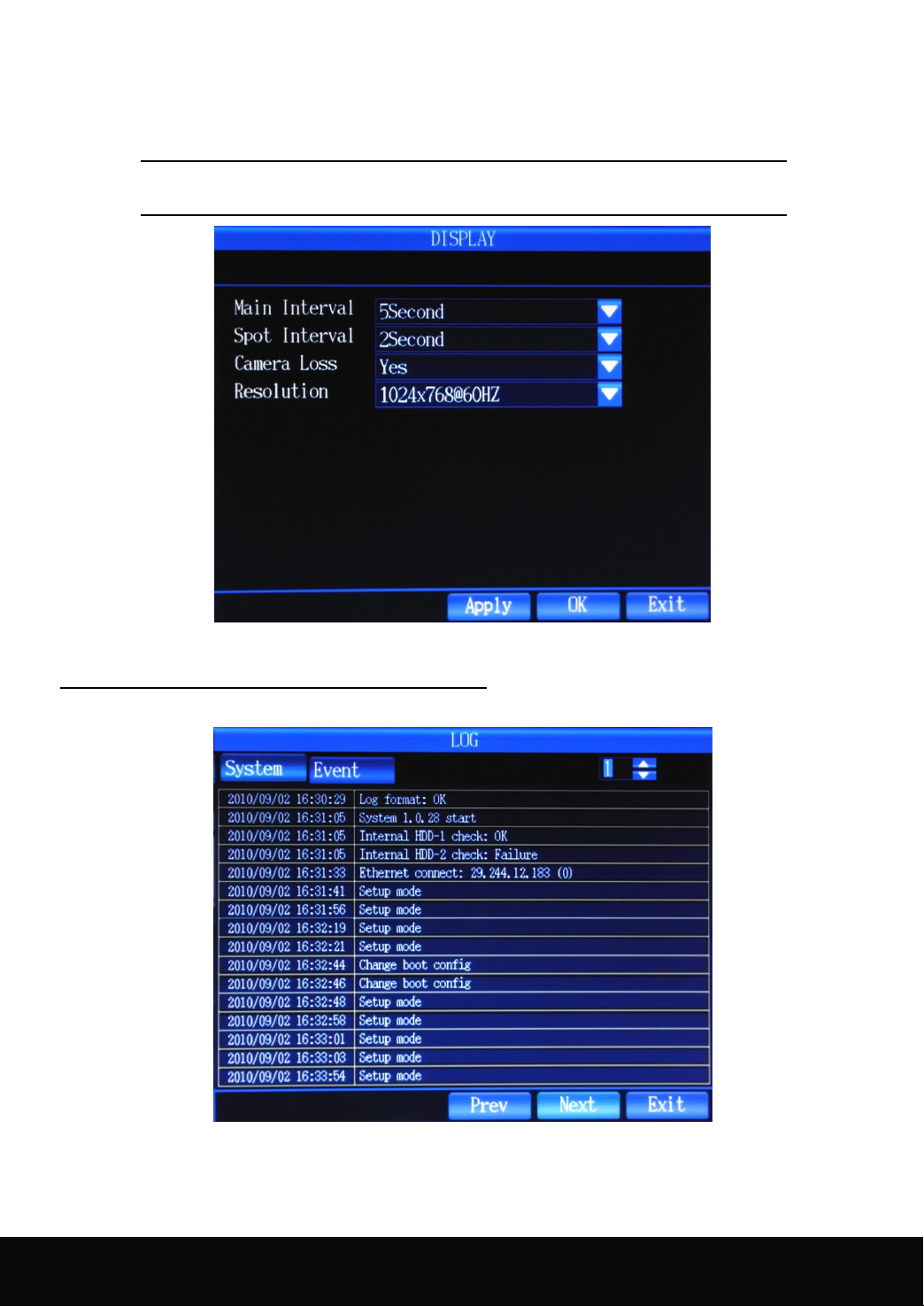
(4) Display Resolution: the resolution setup of VGA or CVBS output port
Setting
Setting
Setting
Setting Method
up the drop -down menu, press the Arrow Keys to select the video output resolution, then press PTZ key to apply
the selected settings.
Method
Method
Method :
:
:
: Press the Arrow Keys to select display resolution(Resolution) column, press PTZ key to pop
4.
7
4.
7
4.
4. 7
7 .
.
8
Log
.
8
Log
. 8
8 Log
Log Search
Notice
Search
Search
Search
Display Output:800*600 60HZ , 1024*768 60HZ , 1280*1024 60HZ
Picture 4- 33
Click "Main Menu" → " Log " to enter the interface as shown in Picture 4- 34
Picture 4- 34
The login and startup of the device would leave a log message. Users could check the log information.
1.
System
1.
System
1.
1. System
System Log
Log
Log
Log
30
16 Channel Embedded Digital Video Recorder User Manual
Page 32
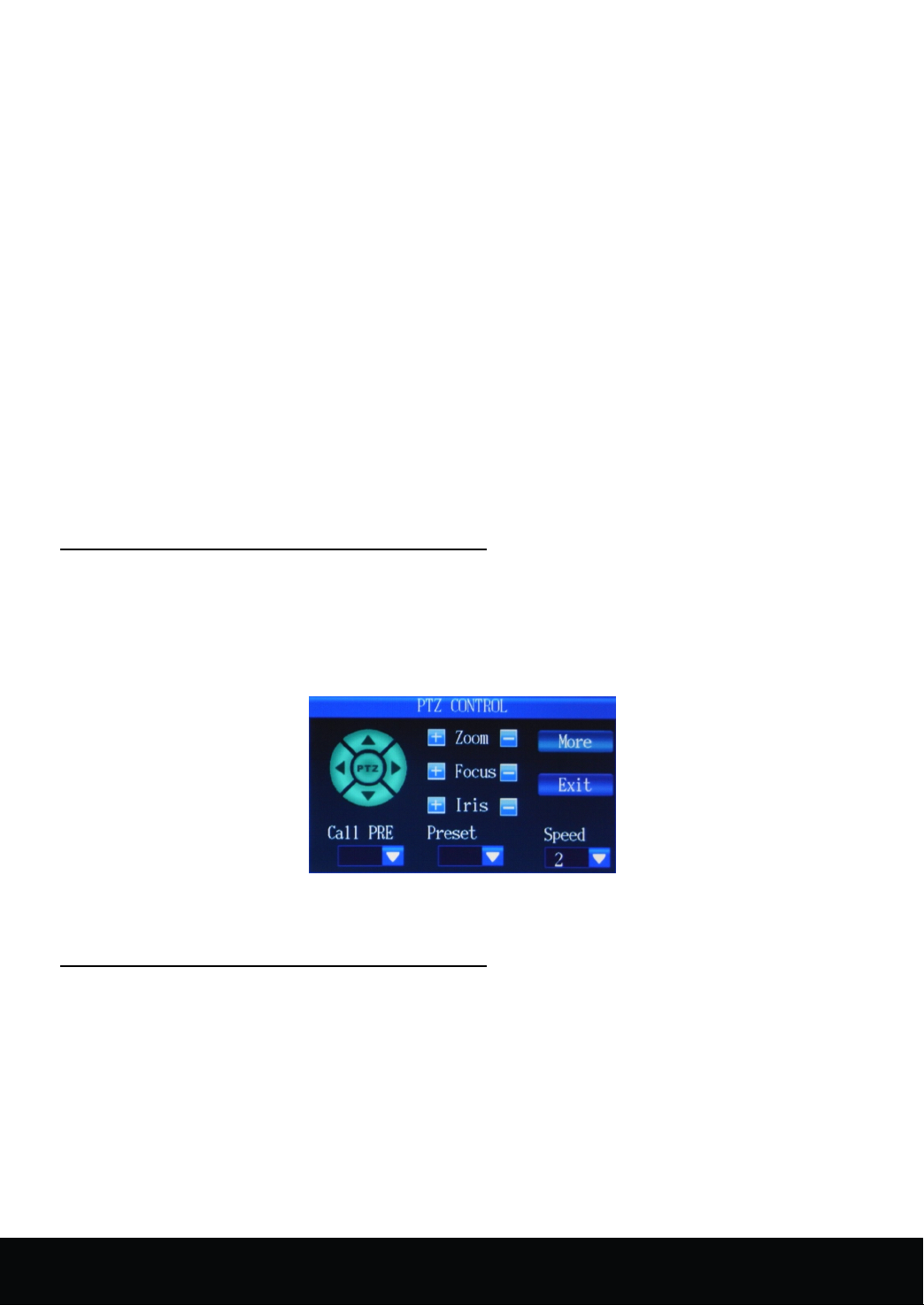
The system log indicates: the record of the normal start, local system login, remote login, system updating.
Setting
Setting
Setting
Setting Method:
(1) In the system log interface, press the arrow keys to select the category query column, press PTZ key to pop
up the drop down menu, then press the arrow keys to select the queried log type, press the PTZ key to apply the
settings.
(2) Setup of the queried time: press the arrow keys to select search button, press PTZ button to enter log list
interface as shown in the below picture
2.
2.
2.
2. Event
wrong password, HDD error.
Setting
Setting
Setting
Setting Method:
(1) In the system log interface, press the arrow keys to select the category query column, press PTZ key to pop
up the drop down menu, and then press the arrow keys to select the queried log type, press the PTZ key to apply
the settings.
(2) Setup of the queried time: press the arrow keys to select "search" button, press PTZ button to enter log list
interface as shown in the above picture.
4.
4.
4.
4. 7
interface.
is as shown in picture 4- 35 . The speed of PTZ could be set. The arrow buttons is used to control the direction of
the high-speed ball movement, press "+","-" button to control zoom, focus, iris.
Method:
Method:
Method:
Event
Log
Event
Log
Event Log
Log
Event log indicates: the records of triggered event deletion, video loss, linkage alarm, dynamic detection,
Method:
Method:
Method:
7
.
9
PTZ
7
.
9
7 .
. 9
9 PTZ
Click the right mouse button → select the "PTZ control" in the right button menu to enter PTZ control
After entering the PTZ control interface, it is very convenient to control the PTZ. The PTZ control interface
Control
PTZ
Control
PTZ Control
Control
Picture 4-35
4.
7
.1
0
4.
4.
4. 7
information interface as shown in picture 4- 36
System
7
.1
0
System
7 .1
.1 0
0 System
System Information
Press ESC key → select the "system information" in the right mouse button menu to enter the system
Information
Information
Information
16 Channel Embedded Digital Video Recorder User Manual
31
Page 33
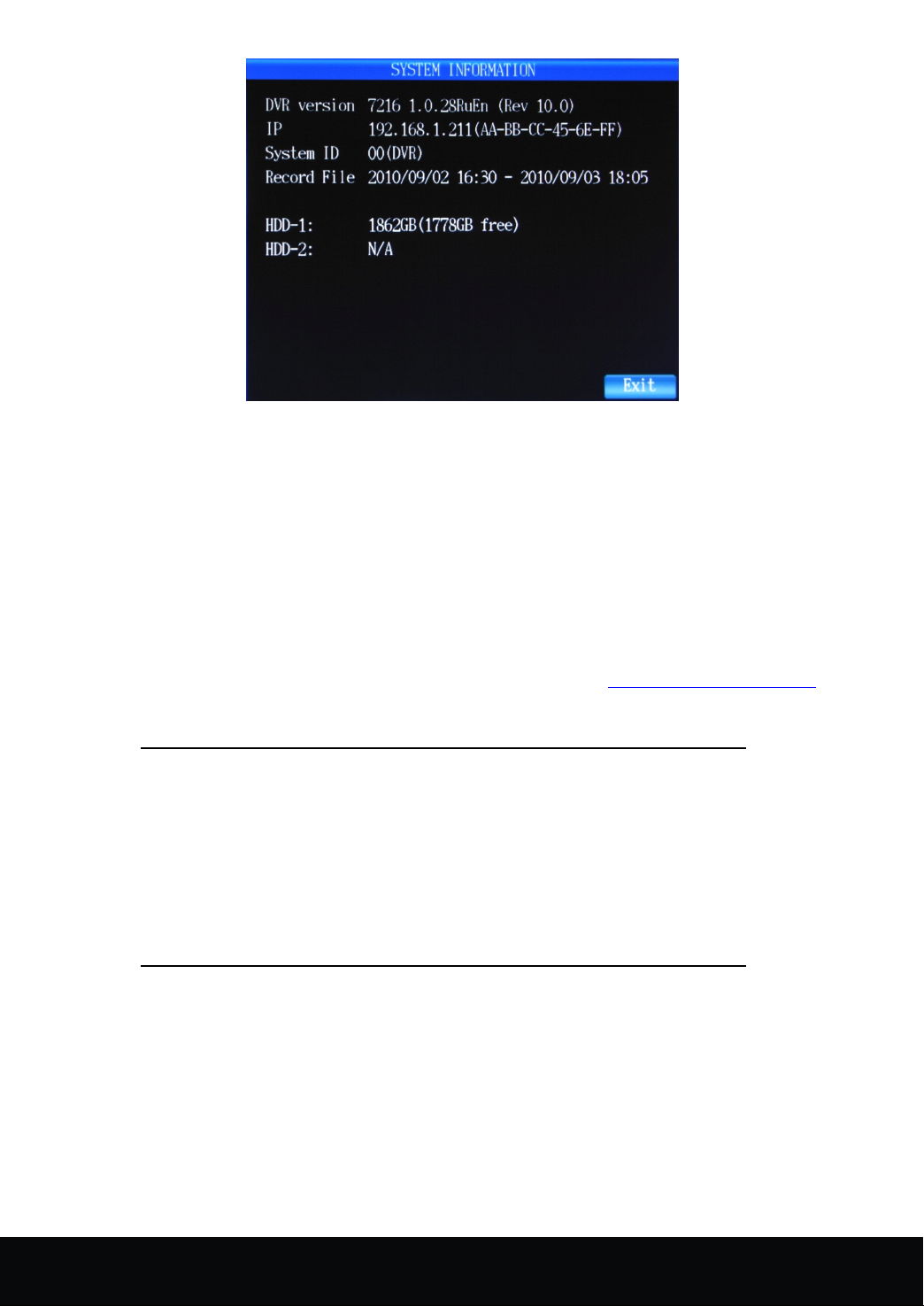
Picture 4- 36
System information interface mainly indicates the DVR Version, web address, system ID, the information
of record files and the information of the built-in HDD.
Chapter
Chapter
Chapter
Chapter 5
5.1
IE
5.1
5.1
5.1 IE
press ENTER key, if your computer is connected to internet, you will be prompted to download and install
"Active X Control"
5.2
5.2
5.2
5.2 IE
password, then click "LOGIN" to view DVR remotely.
Plug-in
IE
Plug-in
IE Plug-in
Plug-in download
Open your web browser, enter the IP address and web port of DVR. Etc: http://192.168.xxx.xxx:8000/ then
IE
Login
IE
Login
IE Login
Login
After the plug-ins installation, (the login interface as shown in picture 5-1)enter the port, user name and
download
download
download and
Notice
1. Pl ease check if the safety levels or firewall setting are set too
advanced.
2. Select IE Tools → Internet Option to enter the security
interface, click the custom levels and set the "downloading
unsigned Active X plug-in" Options as "prompt" click "OK" button
to exit.
5
IE
5
5 IE
and
and
and installation
Unable to download the plug-in problem
and
IE
and
IE and
and Client
installation
installation
installation
Client
Client
Client Software
Software
Software
Software Login
Login
Login
Login
32
16 Channel Embedded Digital Video Recorder User Manual
Page 34
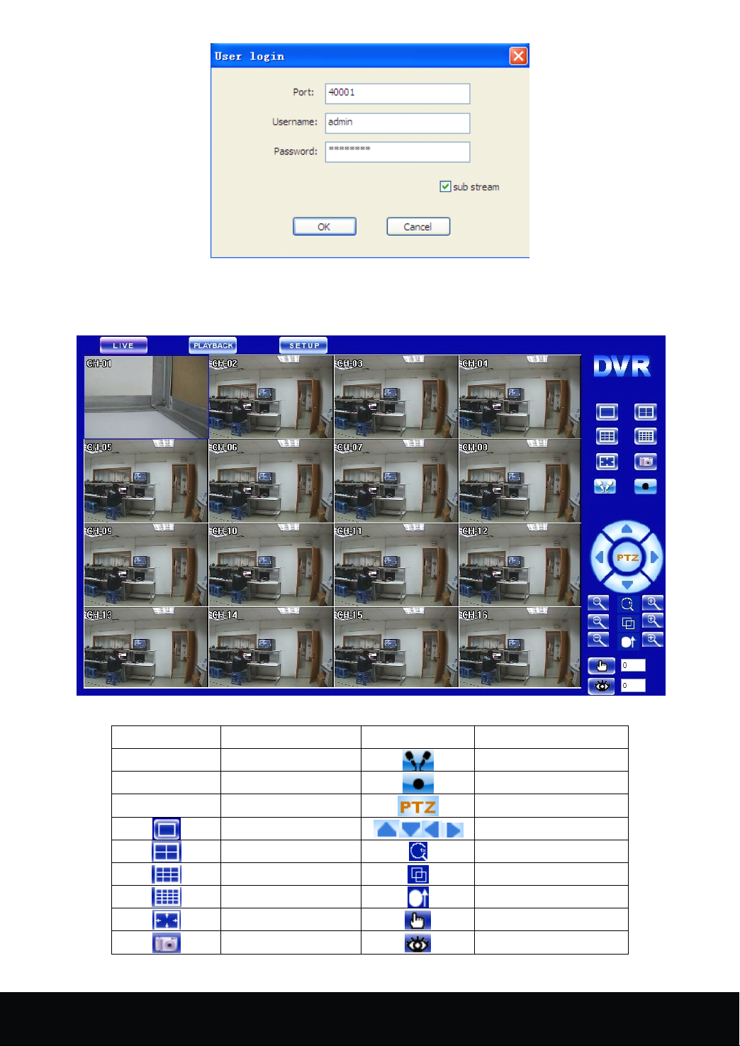
Picture 5-1
The successful login leads to live preview interface as shown in picture 5-2.Click the right mouse button
into "preview control" to choose channel number to have the video link.
Picture5- 2
Indicator
Indicator
Indicator
Indicator Function
LIVE live Intercom
PLAYBACK Play back menu Record
SETUP Setup menu Auto
Function
Function
Function Indicator
1x1 Up,Down,Left,Right
2x2 ZOOM
3x3 FOCUS
4x4
Full screen PRESET
Snap CALL PRESET
Indicator
Indicator
Indicator Function
Function
Function
Function
IRIS
16 Channel Embedded Digital Video Recorder User Manual
33
Page 35
5.3
IE
5.3
5.3
5.3 IE
5.3.1
5.3.1
5.3.1
5.3.1 Menu
5-2
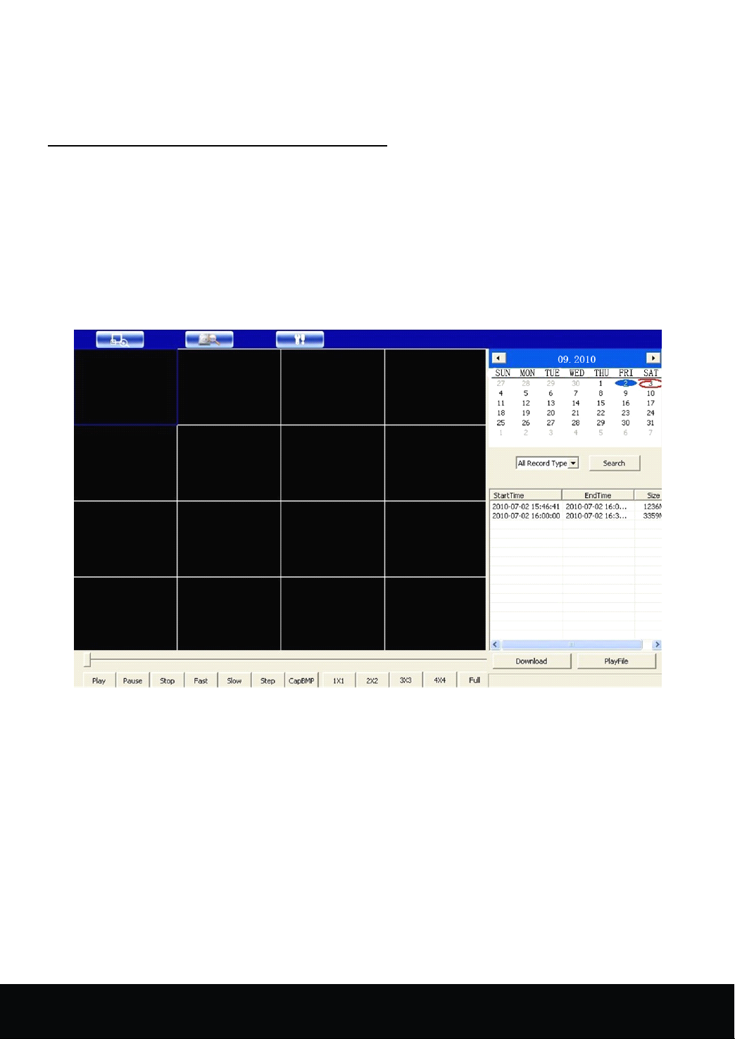
Retrieval: C lick "Retrieval" to review the DVR video files remotely and select to play some files. Click
"Retrieval" after selecting the date and record type, and then select the event play in the event lists of the search
results, meanwhile, use the play control bar at the bottom of the interface to control. As shown in picture 5-3,
users could pause, stop, fast forward, slow play of the selected files.
select the files ,then click "download" button, the files saving path is set in the local setting interface as shown in
picture 5-5.
interface
IE
interface
IE interface
interface
After logging in the client end successfully, the interface is as shown in picture 5-2
Menu
Menu
Menu Bar
Preview: After PC client end log in the system, enter the default live preview interface as shown in picture
Bar
Bar
Bar
To
download the retrieval files, tick and
Picture 5-3
Setup:
Setup:
Setup:
Setup: Click "setup" to pop up secondary menu: remote configuration and local configuration .
select the remote configuration, as shown in picture 5-4
34
16 Channel Embedded Digital Video Recorder User Manual
Page 36
Picture 5-4
Notice
The remote configuration interface mainly indicates system configuration, recording configuration, events
configuration, User Manage.
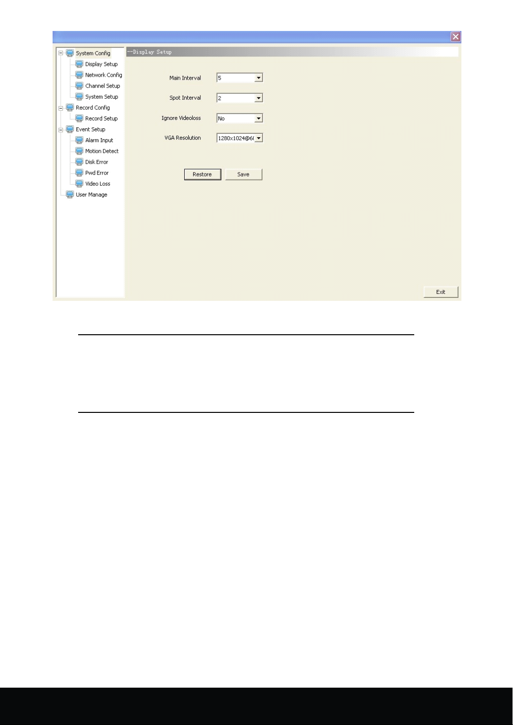
a. System configuration includes display setting, web setting, channel setting, log q uery, system setting.
Click "System Configuration" → "Display Setting" to enter display setting interface as shown in the below
picture. Users can set the main display switching time, SPOT switching time, HDD loss ignoring, display
resolution and OSD output device in the interface.
Setting Method is the same with that of DVR, please refer to 4. 7 .7.
Only when DVR is in the preview main interface, its parameters
can be modified remotely. The settings come into effect after the
parameter savings are submitted to DVR end. The parameter
modification in IE is consistent with the same modification in DVR
end.
16 Channel Embedded Digital Video Recorder User Manual
35
Page 37
Picture 5- 5
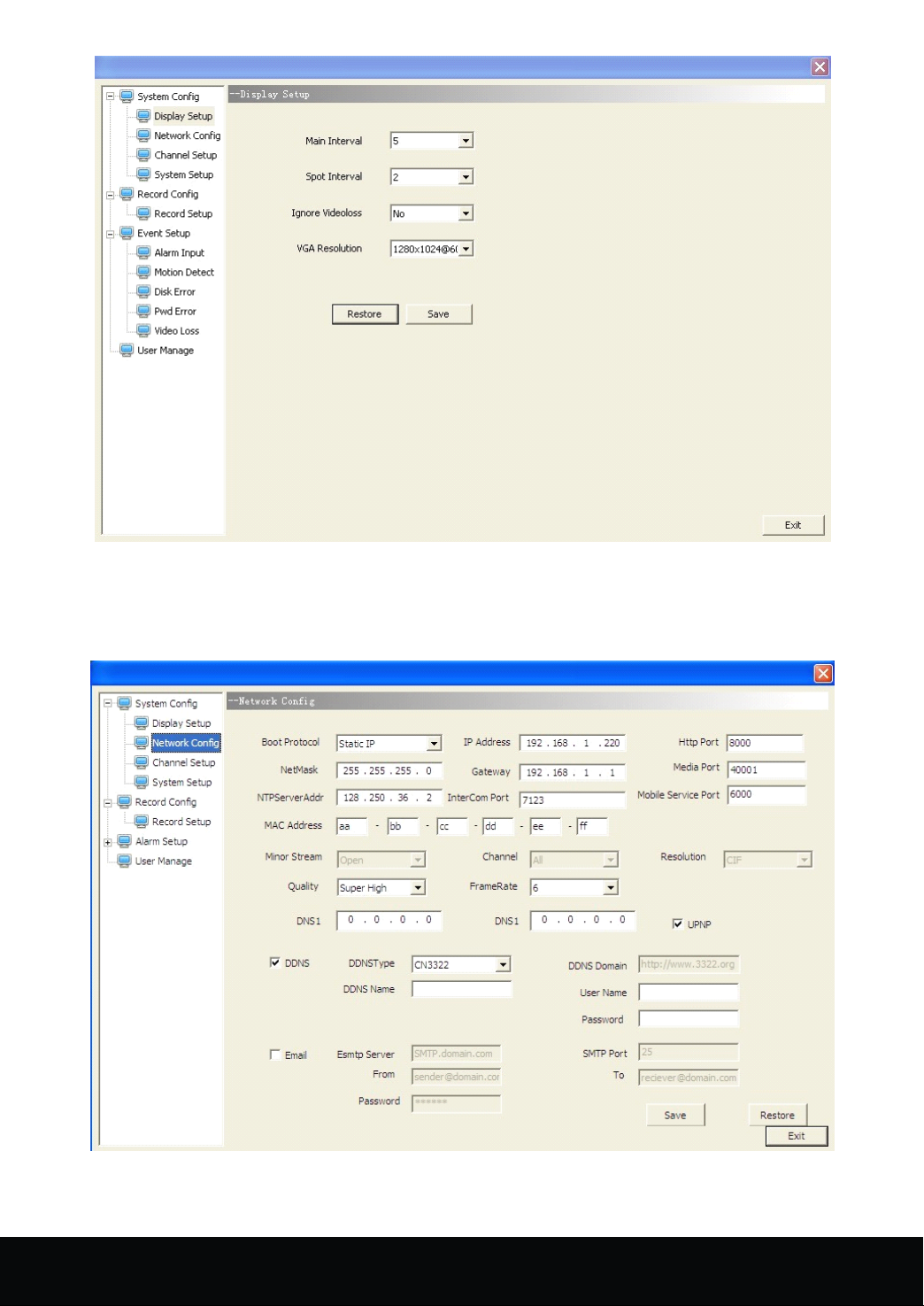
Click "System Configuration" → "Web Setting" to enter web setting interface as shown in below picture.
Users can set the network mode in the interface; the relevant parameters are consistent with those of DVR end.
Please refer to 4. 7 .4.
Picture 5- 6
Click "System Configuration" → "Channel Setting" to enter channel setting interface as shown in below
36
16 Channel Embedded Digital Video Recorder User Manual
Page 38
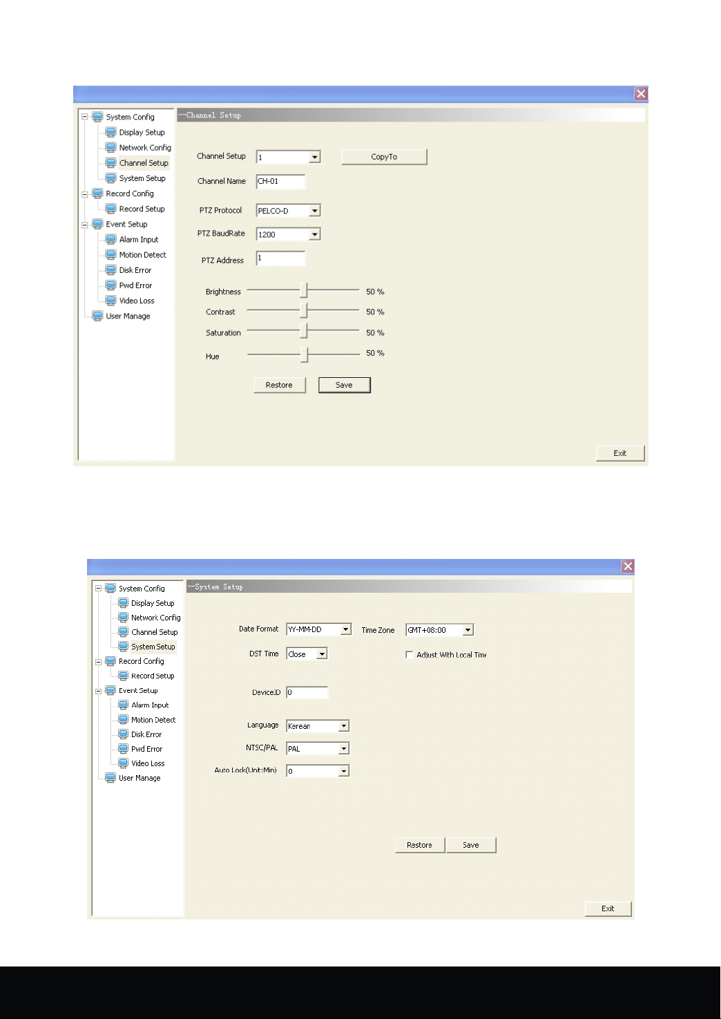
picture. Users can set the channel name, PTZ protocol, PTZ Baud rate, PTZ address and the color in the interface.
The Setting Method is consistent with that of DVR end.
Picture 5- 7
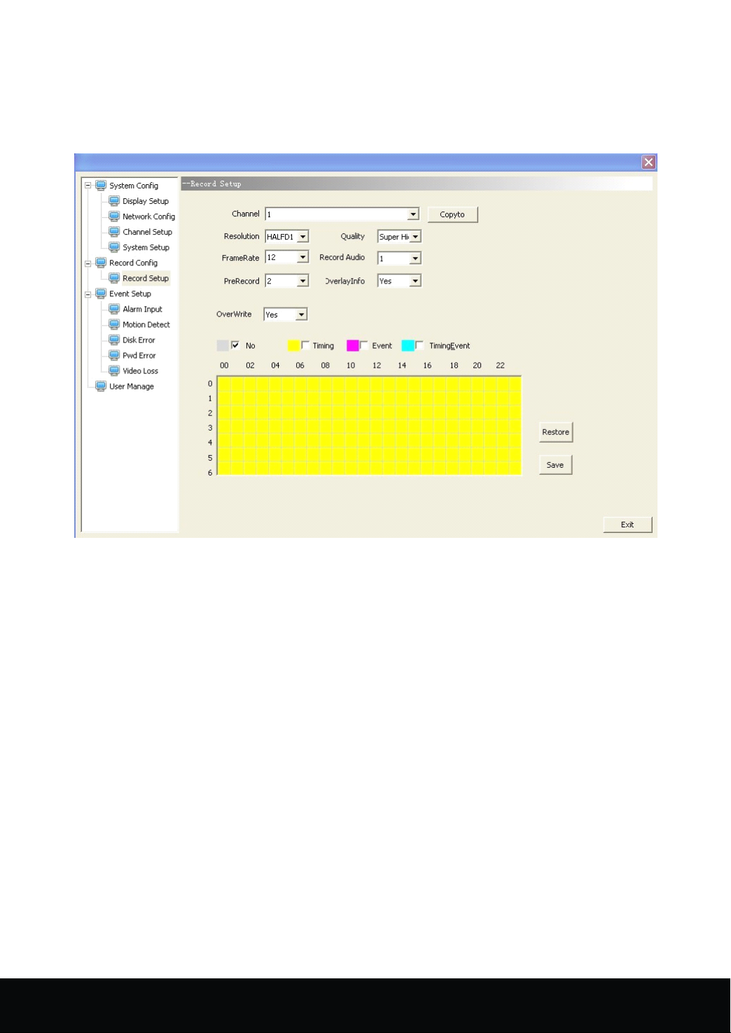
Click "System Configuration" → "System Setting" to enter log query interface as shown in below picture.
Users can set system date format, time zone, system time setting, daylight saving time, device ID, system
language, format option, auto lock in this interface. The Setting Method is consistent with that of DVR end.
Picture 5- 8
16 Channel Embedded Digital Video Recorder User Manual
37
Page 39
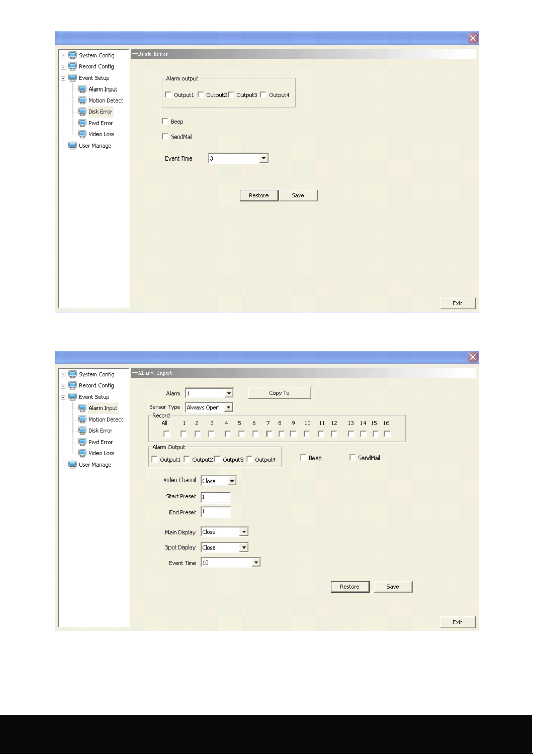
The recording configuration includes recording setting and recording schedule.
Click "Recording Configuration" → "Recording Setting" to enter recording setting interface as shown in below
picture. Users can set recording resolutions, definition, frame rate, sound recording, pre-recorded frame rate,
superposition information and cycle covering in this interface. The Setting Method is consistent with that of
DVR end. Please refer to 4. 7 .1 Basic Setting.
Picture 5- 9
Click "Recording Configuration" → "Recording Schedule" to enter recording schedule interface as shown in
below picture. The recording schedule is mainly set to the recorder. The Setting Method is consistent with that of
DVR end. Please refer to 4. 7 .1Recording Schedule.
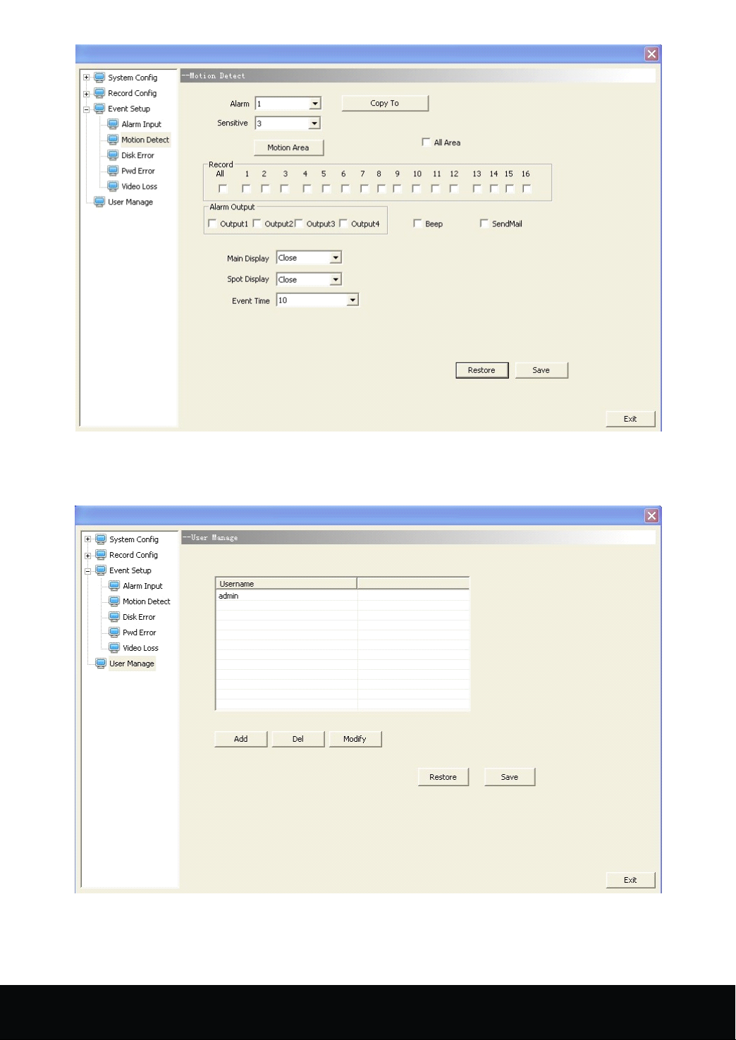
b. Event configuration interface mainly indicates HDD error, password error, video loss, alarm input, motion
detection. The HDD error, password error and video loss interfaces are almost consistent shown as the below
picture.
38
16 Channel Embedded Digital Video Recorder User Manual
Page 40
Picture 5- 10
The alarm input interface is as shown in the below picture
Picture 5- 11
The motion detection interface is as shown in the below picture
16 Channel Embedded Digital Video Recorder User Manual
39
Page 41
Picture 5- 12
c. User Management indicates the adding, deletion and modification of the users.
User manage ment interface is as shown in the below picture
Picture 5- 13
The above Setting Method of the interface is consistent with that of DVR. Please refer to the Setting
Method of DVR.
40
16 Channel Embedded Digital Video Recorder User Manual
Page 42
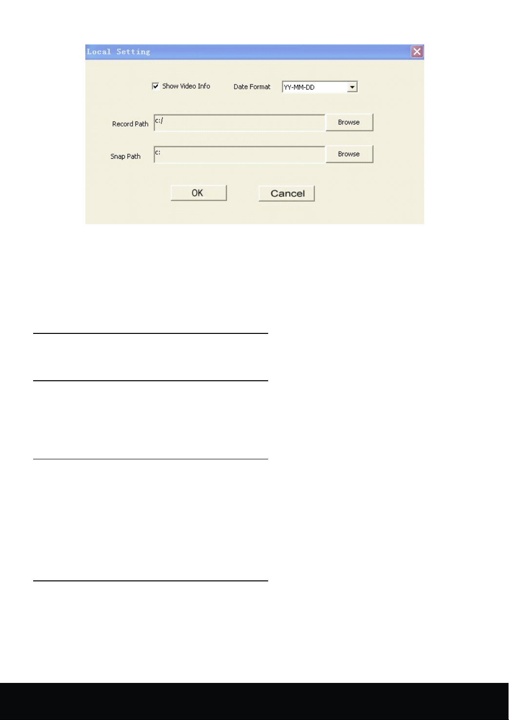
Select the local configuration, the interface is as shown in picture 5- 14
Picture 5- 14
The local configuration includes spot overlay characters, record path and snap path
A. Live overlay characters indicate the d isplaying channel name set during the live preview.
B. The record path indicates the saving path of the downloading record videos
C. The snap path indicates the saving path of the screenshot images.
5.3.2PTZ
5.3.2PTZ
5.3.2PTZ
5.3.2PTZ Control
PTZ Control: the zoom, focus and iris control of PTZ.As shown in picture 5 -2 .
5.3.3
5.3.3
5.3.3
5.3.3 Video
Under the state of live preview, the preview screen can be split by pressing the switch button of video
window. It supports single screen, four screens, nine screens, 16 screens and full screen operation. As shown in
picture 5 -2.
5.3.4
5.3.4
5.3.4
5.3.4 Playback
Under the state of live preview, click the " Playback " button to enter record query interface. Click " seach "
button after selecting the date and type of the files. Then select the particular event in the searched event lists to
play. Meanwhile, users can operate the play control bar at the bottom of the screen to control (as shown in
picture 5 -3) the pause, stop, fast forward, slow forward and so other operations. During the course of playback,
the screen could be split. The device support single screen, four screens, nine screens, sixteen screens and full
screen playback at present.
5.3.
5
5.3.
5
5.3.
5.3. 5
5 Snapshot
Under the state of live preview, c lick the "snapshot" botton,Can operate the snapshot of the current
previewed picture. As shown in picture 5-2 .
Control
Control
Control
Video
Video
Video Switch
Playback
Playback
Playback
Snapshot
Snapshot
Snapshot
Switch
Switch
Switch
16 Channel Embedded Digital Video Recorder User Manual
41
Page 43
5.4
Client
5.4
Client
5.4
5.4 Client
Client software
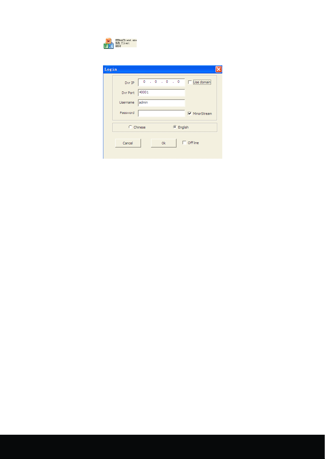
Pls open the file"player.exe "( ) in the CD Files,the interface is as shown in the following
image:
User
User
User
User Name:
Password:
Password:
Password:
Password: DVR Password(Defauted PW is 00000000)
Minor
Minor
Minor
Minor Stream:
Stream.Otherwise,it is main stream.
Language:
Language:
Language:
Language: Language Options,Support Chinese and English
Offline:
Offline:
Offline:
Offline: Offline Play Function
software
software
software login
Name:
Name:
Name: DVR User Name(Defauted User Name is admin)
Stream:
Stream:
Stream: After ticking √ in this option,the stream of the system transfer is minor
login
login
login
The
operation
The
operation
The
The operation
operation interface
end.Pls
end.Pls
end.Pls
end.Pls just
1.
1.
1.
1. What
A: Check if the power supply system is properly connected and data cord and power cables accurately
connected.
2.
2.
2.
2. We
A: If you forget system password, please consult with the service personnel. Setting a easy-to-remember and safe
password is much recommended. (If any security requirements, please do not try to set the simple passwords
such as 000000)
3.
3.
3.
3. We
A: Check camera video cable and connections; or check monitor video cable and connections; or confirm that
the camera has the power and / or check camera lens setting.
4.
4.
4.
4. What
What
What
What can
We
have
We
have
We have
have changed
We
are
We
are
We are
are not
What
What
What is
just
just
just refer
refer
refer
refer to
can
I
can
I
can I
I do
changed
changed
changed the
not
getting
not
getting
not getting
getting any
is
the
is
the
is the
the affect
interface
interface
interface of
to
to
to the
do
if
do
if
do if
if the
affect
affect
affect to
of
of
of the
the
setting
the
setting
the setting
setting and
Chapter
Chapter
Chapter
Chapter 6
the
system
the
system
the system
system cannot
the
password
the
password
the password
password but
any
video
any
video
any video
video signal
to
equipment
to
equipment
to equipment
equipment by
the
Client
the
Client
the Client
Client Software
and
and
and operation
cannot
cannot
cannot detect
but
but
but do
signal
signal
signal on
by
by
by DVR
Software
Software
Software after
operation
operation
operation method
detect
detect
detect the
do
not
do
not
do not
not remember
on
the
on
the
on the
the DVR,
DVR
DVR
DVR '
after
logging
after
logging
after logging
logging is
method
method
method of
6
6
6 Troubleshooting
the
HDD?
the
HDD?
the HDD?
HDD?
remember
remember
remember the
DVR,
DVR,
DVR, what
'
s
heat?
'
s
heat?
' s
s heat?
heat?
of
IE
of
IE
of IE
IE
Troubleshooting
Troubleshooting
Troubleshooting
the
new
the
new
the new
new password,
what
is
what
what is
wrong?
is
wrong?
is wrong?
wrong?
is
just
the
is
just
the
is just
just the
the same
password,
password,
password, how
same
same
same of
how
how
how can
of
the
of
the
of the
the interface
can
we
can
we
can we
we access
interface
interface
interface on
access
access
access the
on
IE
on
IE
on IE
IE
the
system?
the
system?
the system?
system?
42
16 Channel Embedded Digital Video Recorder User Manual
Page 44

A: The DVR has a fan to help it dissipate heat while it is running. Please place the DVR in a place where there is
good air circulation and away from heat sources to increase stability and life of the DVR.
5.
Why
the
5.
Why
5.
5. Why
Why the
A: If the controller is pointing to the IR signal on equipment front panel, but the operation is still invalid, please
check the batteries in remote controller, if above problems are excluded, please check the health of the remote
controller
6.
When
6.
When
6.
6. When
When my
A: It works as long as the DVR system supports the HDD. But note that the data of the HDD will be lost when
DVR is operating.
7.
Can
7.
Can
7.
7. Can
Can we
A:
Yes,
8.
Can
8.
Can
8.
8. Can
Can we
A: Considering the safety factor, you can ' t delete the recorded file directly from the device. When you actually
erase all the recorded files, please select HDD format function
9.
Why
9.
Why
9.
9. Why
Why can't
A: Please check if the web connection configurations are all right and the RJ-45 interface connection is ok. Or
when the web password switch is on, check if the account and password are right or not.
10.
There
10.
There
10.
10. There
There is
A: It ' s normal if less than 5 seconds;
11.
Cannot
11.
Cannot
11.
11. Cannot
Cannot find
A: please check the harddisk data cable connection, and whether system time is adjusted illegally. Try it several
times, and test whether the harddisk is damaged if above still appears.
DVR
12.
DVR
12.
12.
12. DVR
DVR cannot
A: Please test for the following reasons:
① Front PTZ failure
② PTZ decoder setting, connection and installation is incorrect
③ PTZ incorrect setup in the DVR
Remote
the
Remote
the Remote
Remote Controller
my
my
my PC
we
record
we
record
we record
record while
you can do it. The system support s that you record while playing-back.
we
erase
we
erase
we erase
erase some
can't
can't
can't login
is
drag
is
drag
is drag
drag mark
find
find
find any
cannot
cannot
cannot control
Controller
Controller
Controller can
PC
HDD
PC
PC HDD
login
login
login DVR
is
HDD
is
HDD is
is installed
while
playing-back?
while
playing-back?
while playing-back?
playing-back?
some
recorded
some
recorded
some recorded
recorded file
DVR
client
DVR
client
DVR client
client end?
mark
on
mark
on
mark on
on screen
any
information
any
information
any information
information record
control
control
control the
can
can
can '
installed
installed
installed into
file
file
file from
end?
end?
end?
screen
screen
screen when
record
record
record during
the
PTZ
the
PTZ
the PTZ
PTZ after
'
t
work
'
t
' t
t work
into
into
into DVR,
from
from
from DVR?
when
when
when real-time
after
after
after setup?
normally?
work
normally?
work normally?
normally?
DVR,
does
DVR,
does
DVR, does
does it
DVR?
DVR?
DVR?
real-time
real-time
real-time monitoring
during
during
during the
setup?
setup?
setup?
it
work?
it
work?
it work?
work?
monitoring
monitoring
monitoring in
the
playback?
the
playback?
the playback?
playback?
in
client
in
client
in client
client end,
end,
even
end,
even
end, even
even short
short
short
short delay?
delay?
delay?
delay?
④ PTZ protocol decoder and DVR does not match each other
⑤ PTZ decoder and DVR address does not match each other
⑥ When multiple decoders are connected, 120 ohm resistance is n eeded on the most remote end of PTZ
decoder AB line, to eliminate reflex and impedance matching, or PTZ control will not be stable.
13.
Motion
13.
Motion
13.
13. Motion
Motion detection
A: Check the motion detection time and motion detection zone and make sure that they are right setup, and
check the sensitivity setting.
14.
Alarm
14.
Alarm
14.
14. Alarm
Alarm does
A: Check the correctness of alarm setting and alarm connection, and make sure that alarm signal input is correct.
15.
Why
15.
Why
15.
15. Why
Why does
A: Please check if motion detection is on and the system has detected motion, make sure the HDD is being
detected and has sufficient space available; check if video has lost etc.
detection
detection
detection does
does
not
does
not
does not
not work?
does
the
does
does the
Buzzer
the
Buzzer
the Buzzer
Buzzer keep
does
does
does not
work?
work?
work?
not
work?
not
work?
not work?
work?
keep
sounding?
keep
sounding?
keep sounding?
sounding?
16 Channel Embedded Digital Video Recorder User Manual
43
Page 45
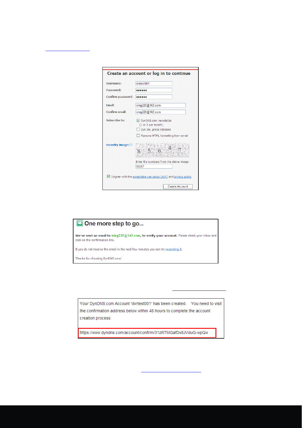
Appendix
Appendix
Appendix
Appendix 1
1) Create account
First open www.dyndns.com , and click the Create Account option:
Fill in the account information.
1
Domain
1
Domain
1 Domain
Domain name
name
name
name application
application
application
application
After confirmation, the system will prompt that the verification message has been sent to the designated
mailbox, as shown below:
2) Activate account
Click the link below and enter the website to activate the account.
3) Login
After successful activation, open the home page http://www.dyndns.com/ to log in. After successful login,
click “ Services ” →“ Dynamic DNS ” , as shown below:
44
16 Channel Embedded Digital Video Recorder User Manual
Page 46
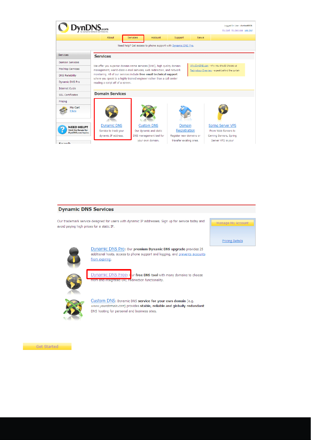
4) Application for free domain name
After entering the “ Dynamic DNS Services ” screen, click “ Dynamic DNS Free ” to apply for a free
dynamic domain name, as shown below:
Enter the “ Dynamic DNS Free ” screen, as shown below. Click
“ ” .
16 Channel Embedded Digital Video Recorder User Manual
45
Page 47
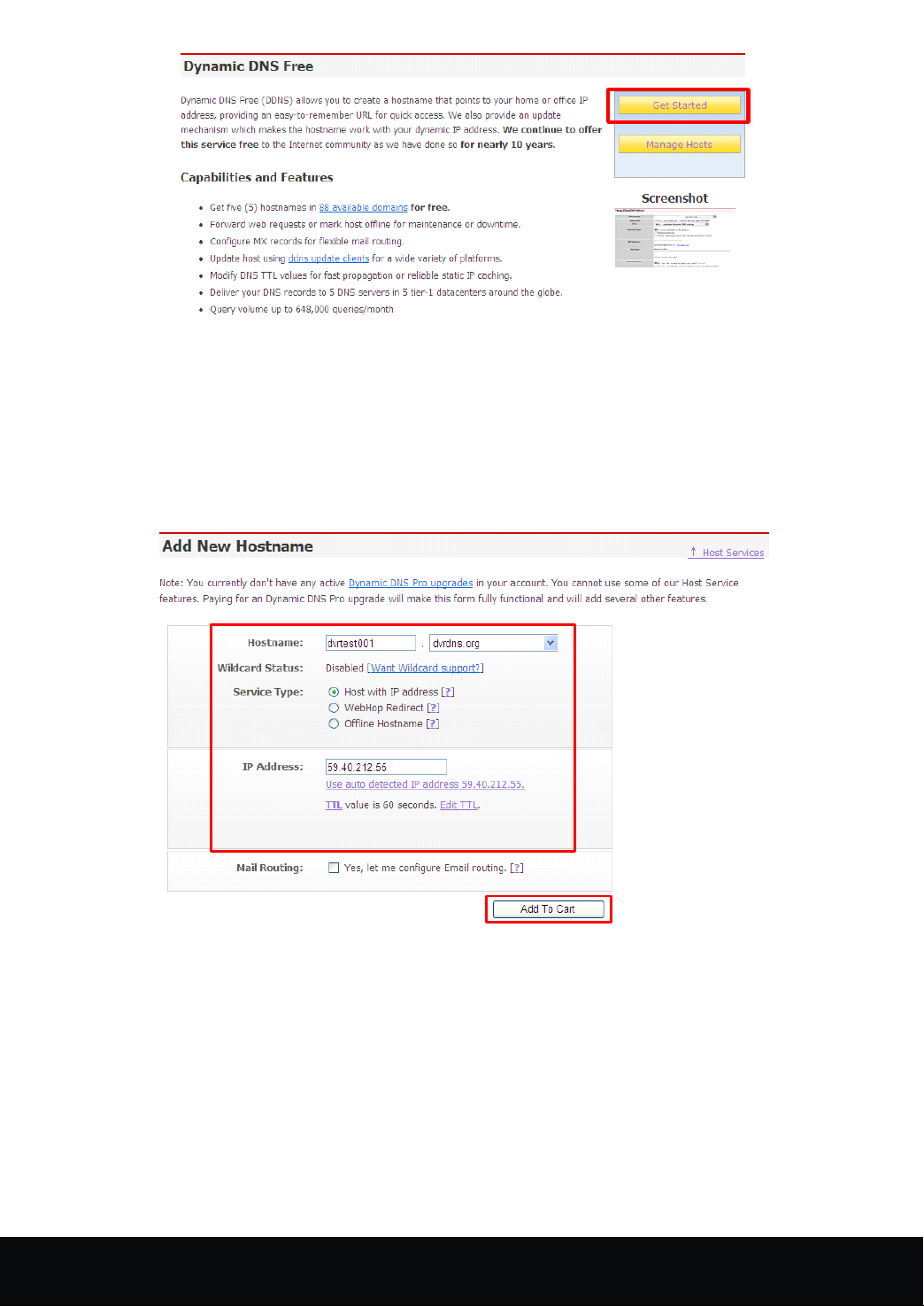
Enter the hostname, select the service type and then enter the dynamic IP address (usually being the
dynamic IP address of the network of the DVR host) to be tied in the Add New Hostname screen, as shown
below. Complete the application for the dynamic domain name as prompted.
46
16 Channel Embedded Digital Video Recorder User Manual
Page 48
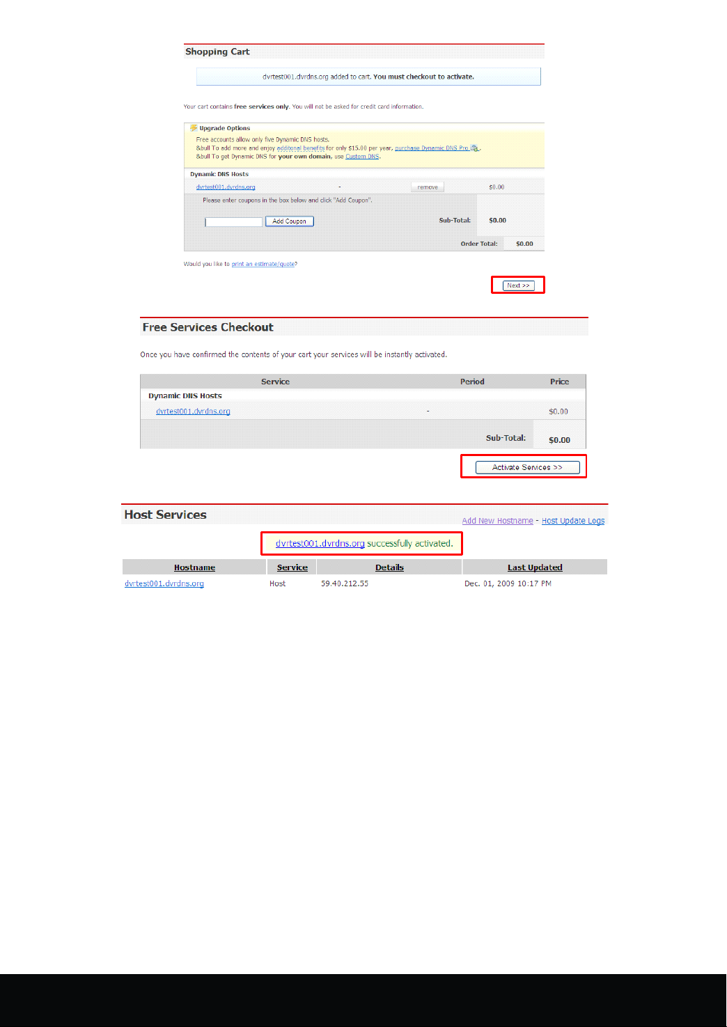
16 Channel Embedded Digital Video Recorder User Manual
47
Page 49
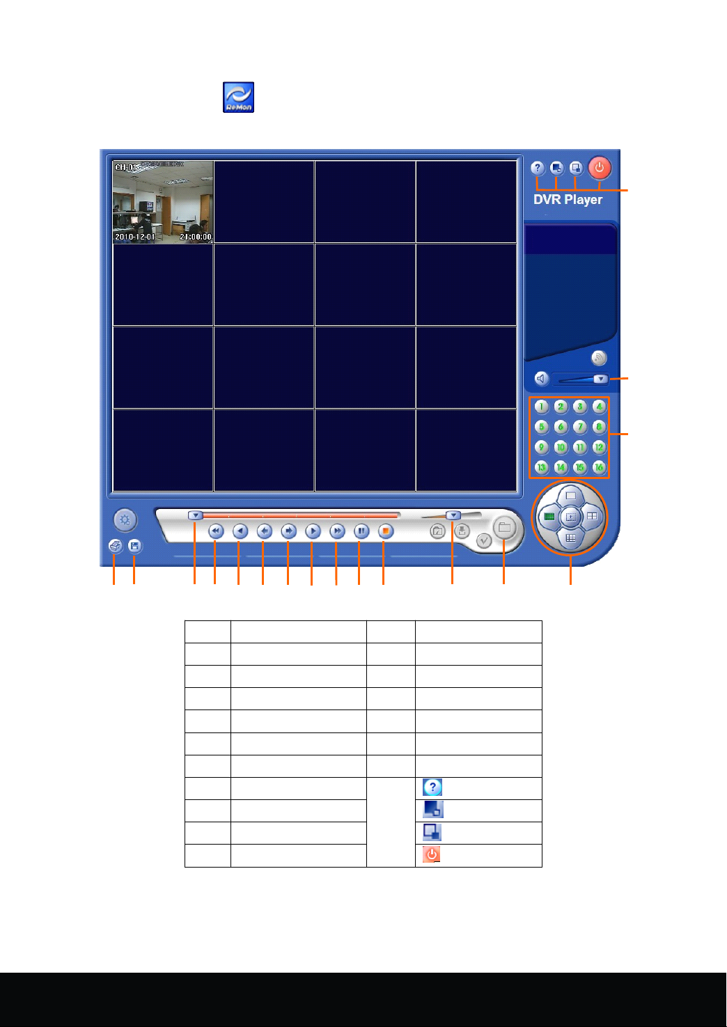
Appendix
Appendix
Appendix
Appendix 2
Pls open the file "player.exe "( ) in the CD Files,the interface is as shown in the following image:
2
Player
2
Player
2 Player
Player
17
16
15
1 2
4 5 6
3
NO.
NO.
NO.
NO. Function
1 Image print 11 Stop
2 Image save 12 Play speed
3 Play bar 13 Open file
4 Fast backward 14 Display mode
5 Backward play 15 1~16 Channel
6 Step backward 16 Audio
7 Step forward 17
8 Play
9 Fast forward
10 Pause
7 8 9 10 11
Function
Function
Function NO.
NO.
NO.
NO. Function
12
Function
Function
Function
:about
:full screen
:minimize
:Exit
13 14
48
16 Channel Embedded Digital Video Recorder User Manual
Page 50
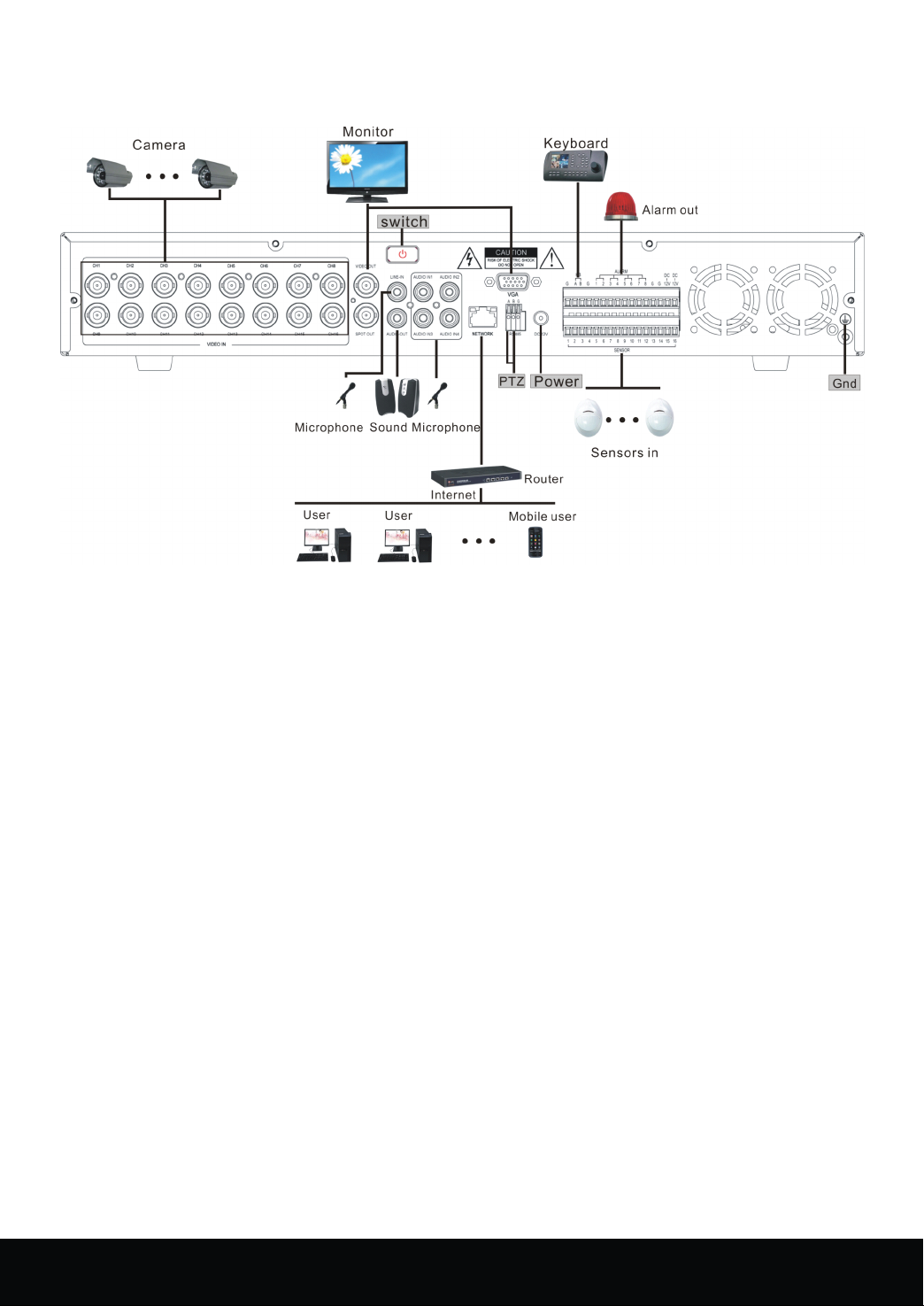
Appendix
Appendix
Appendix
Appendix 3
3
S
ystem
3
S
ystem
3 S
S ystem
ystem connection
connection
connection
connection diagram
diagram
diagram
diagram
16 Channel Embedded Digital Video Recorder User Manual
49
Page 51

▲ Nothing contained in the manual attached to this product
shall be duplicated, disseminated, transcribed or stored in
any retrieval system or translated into any other language
without written consent.
▲ The product specifications and information contained in
this manual are for reference only, and the contents
thereof are subject to updating without notice.
▲
We
assume no responsible for any damage arising from
the improper use of this product. The product names
mentioned in this manual are intended for identification
only, and may also be registered trademarks or copyrights
owned by other companies.
▲ The product color provided in this marketing package may
differ from the color shown on the original package. The
pictures are for reference only. The technical specifications
are subject to change without notice. The accessories
available may differ from market to market. Please consult
your local dealer.
▲ This manual has been checked carefully but any spelling
or technical error is not precluded. Such error or omission
will be corrected in the new version.
modify any and all information contained in this manual
without notice.
50
16 Channel Embedded Digital Video Recorder User Manual
We
have the right to
 Loading...