

Page 1

1
XTB4 LINKED BENCHING
UN0001 Rev. A
Height Adjustable Benching
XTB4 Installation Guide
Page 2

2
Table of Contents:
i. Parts & Fasteners Included ………………………………………………………………………………3
ii. Tools & Supplies Required ……………………………………………………………………………….6
iii. Rectangular Back-to-Back Benching ……………………………………………………………….7
iv. Optional Additions (Screens/End Panels) ……………………………………………………….12
v. 120 Degree Benching ………………………………………………………………………………………13
vi. Single Sided Benching …………………………………………………………………………………….16
vii. Extended Corner Benching ……………………………………………………………………………..19
viii. Handset Instructions ………………………………………………………………………………………23
Page 3
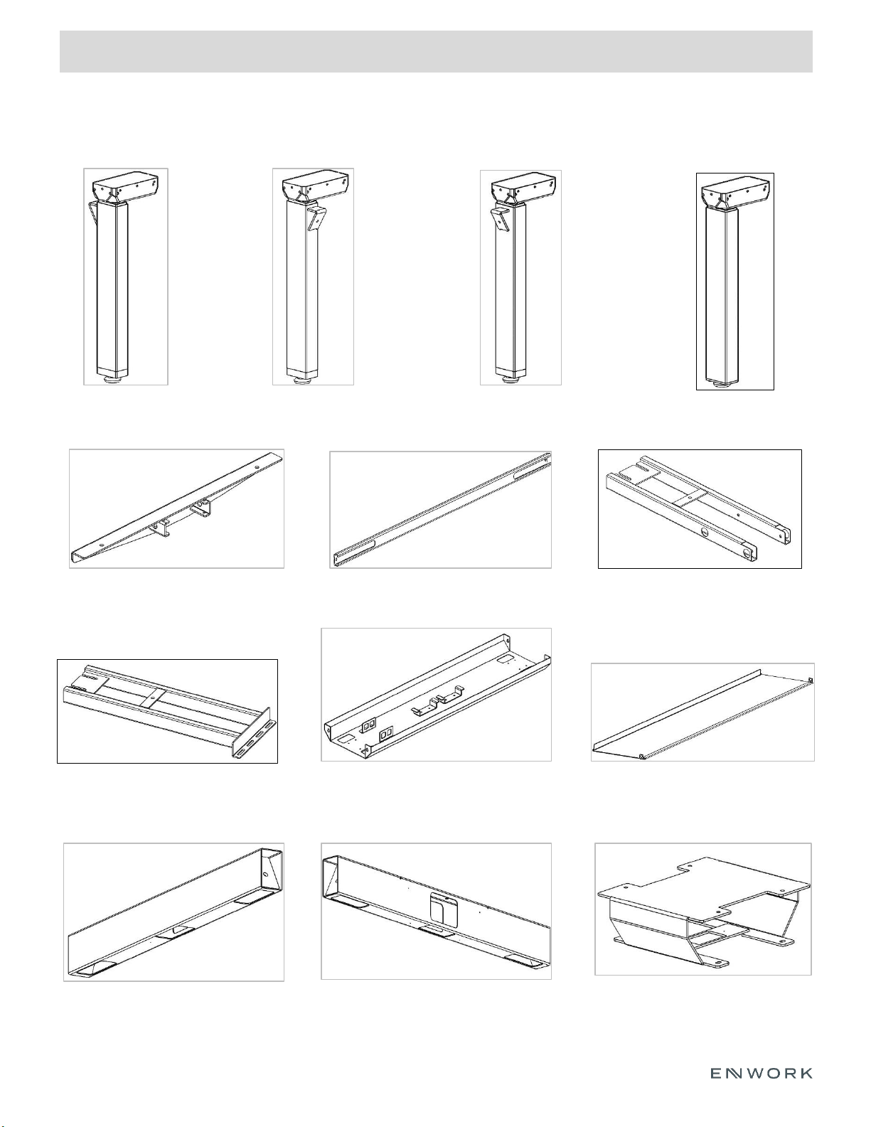
1) Parts and Fasteners Included
INSTALLATION GUIDE
3
Right Leg Column Left Leg Column
*120 Degree - Rear Column
Top Support Bracket Center Rail Support Frame End w/ Control Plate
*Extended Corner Frame Power Trough Trough Cover
Mid Link Connector
End Link Mid Link
*Extended Corner – 3
rd
Leg Column
* - Optional part included with corresponding Single Sided, 120 Degree, or Extended Corner configuration
Page 4
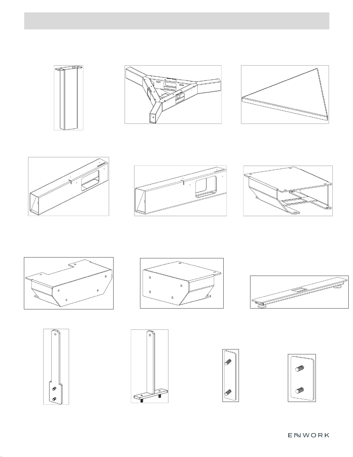
1) Parts and Fasteners Included
INSTALLATION GUIDE
4
In-Feed Leg
*120 Degree Mid Link (120
Degree)
*120 Degree Mid Link Cover
(120 Degree)
*End Link – Single sided *Mid Link – Single Sided
*Foot
*End Panel Bracket - Double Sided
*Screen Bracket -
Double Sided
*Screen Bracket -
Single Sided
*Mid Link Connector – Single Sided
* - Optional part included with corresponding Single Sided, 120 Degree, or Extended Corner configuration
*End Panel Bracket - Single Sided
*Cover – Double
Sided
*Cover – Single
Sided
Page 5
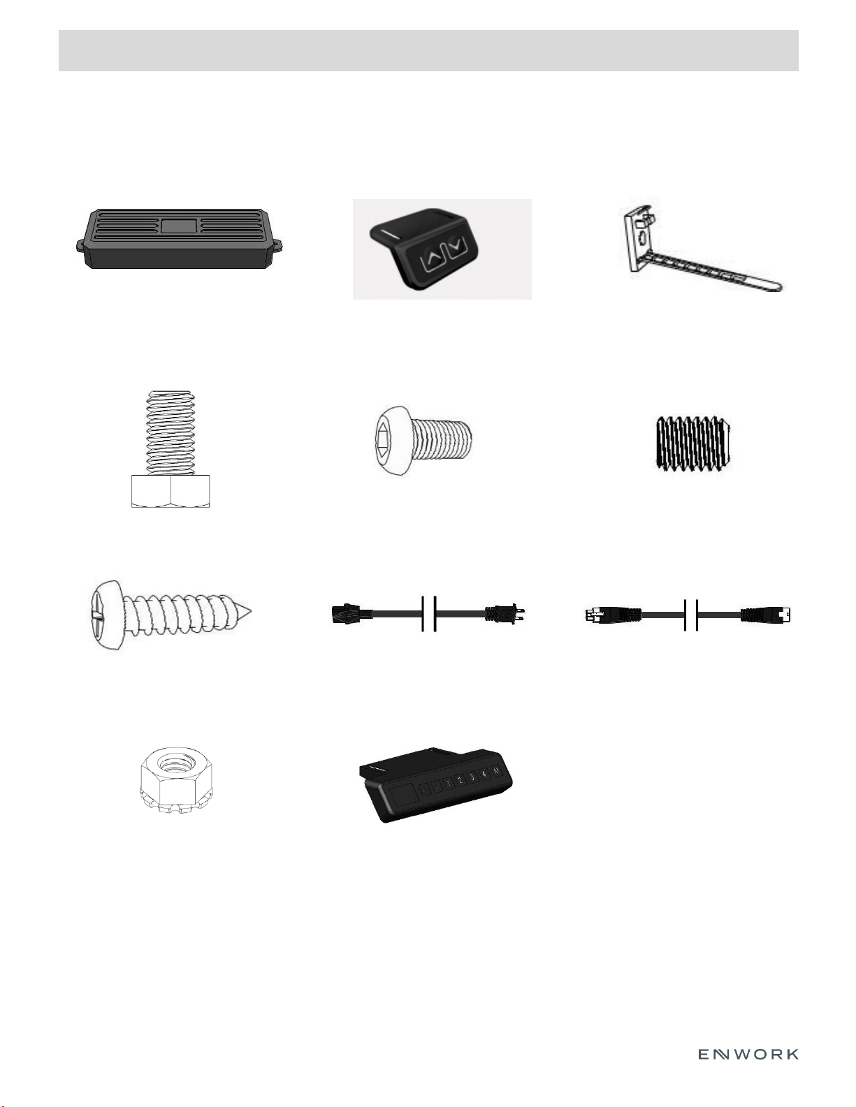
1) Parts and Fasteners Included
INSTALLATION GUIDE
5
Control Box
Handset Cable ties
M6 x 1.0 Button Head
Hex Screw
Set Screw (pre-installed)
Wood Screw Power Cable
Leg Cable
M8 x 1.25 Hex Head Bolt
M6 x 1.0 Locknut w/ external tooth
lock washer
*Programmable Handset
* - Optional part
Page 6
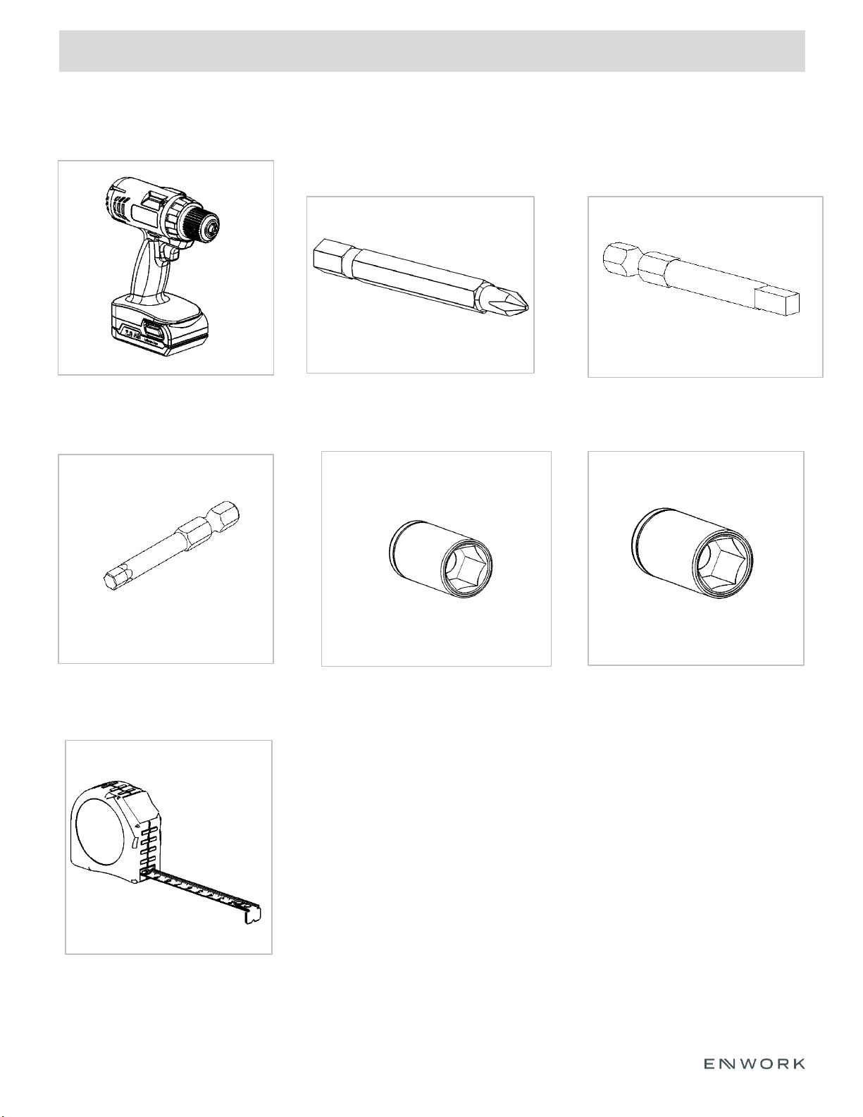
2) Tools and Supplies Required
INSTALLATION GUIDE
6
4mm Hex Bit
10mm Socket
Drill
Phillips Bit
Square Bit
13mm Socket
Tape Measure
Page 7
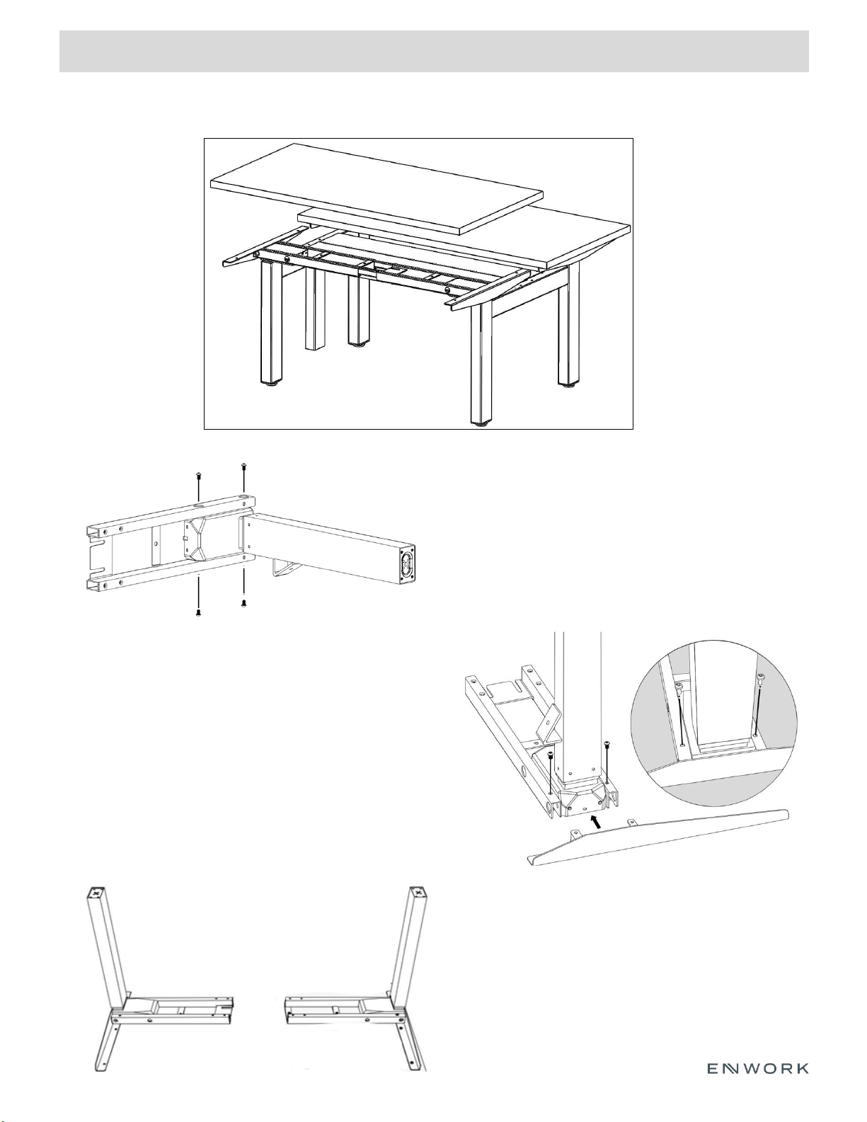
3) Assembly:
INSTALLATION GUIDE
7
3.1.1) Insert a Right Leg Column into a Frame
End w/ Control Plate using (4) M6 x 1.0 Button
head hex screws. Do not fully tighten at this
time.
3.2.1) Attach a Top Support Arm using (2) M6 x 1.0
Button head hex screws. Do not full tighten.
3.2.2) Once Frame and Arm are in place together,
tighten all screws completely.
**Note** The two tabs on the support arm will slot
into the frame end, surrounding the leg column.
3.3.1) Repeat previous steps to assemble
remaining leg columns, frame ends, and top
support brackets.
Fig 3.1
Fig 3.2
Fig 3.3
Standard Benching
2-Pack Rectangular Bench Shown
Page 8
3) Assembly:
INSTALLATION GUIDE
8
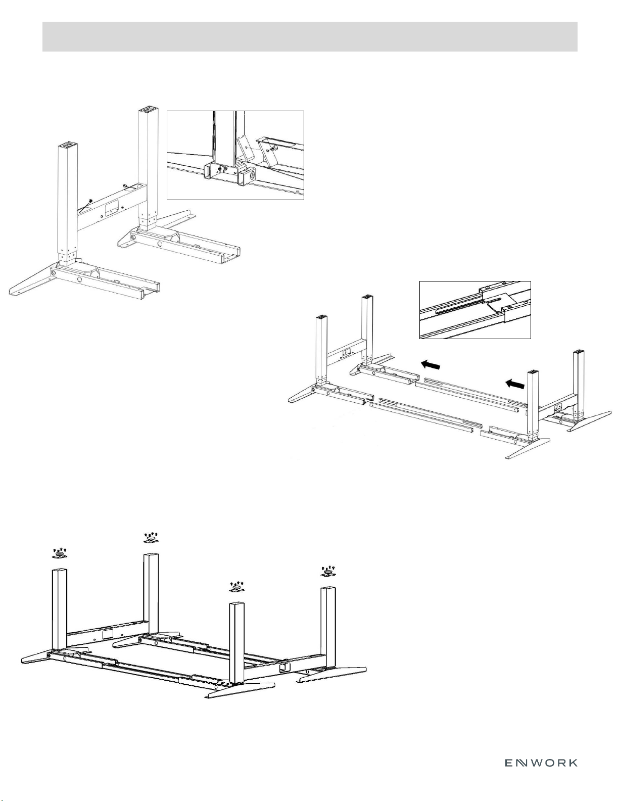
3.5.1) Slide center rail supports into leg assemblies
so that the midpoint mark is facing up and the slot-
cuts are facing inwards. Do not fully tighten set
screws at this step.
**Note** Orientation of center rail supports
3.4.1) Connect one Right leg assembly and one
Left leg assembly together using an End link and
(2) M8 x 1.25 Hex Head bolts. *See section detail
for alignment
3.4.2) Repeat previous step on left leg assembly
using a Mid link.
**Note** Mid-Link has a pass thru-hole. End-Link
will have one closed vertical face. Use the Mid-link
when additional desk pairs are needed. Use the
End-links where no additional desks will be used.
Fig 3.5
Fig 3.6
Fig 3.4
3.6.1) If not already, attach each stand-off
using (4) M6 x 1.0 Button head hex screws
3.6.2) Insert levelers if not already in place.
Standard Benching Cont.
Page 9
3) Assembly:
INSTALLATION GUIDE
9
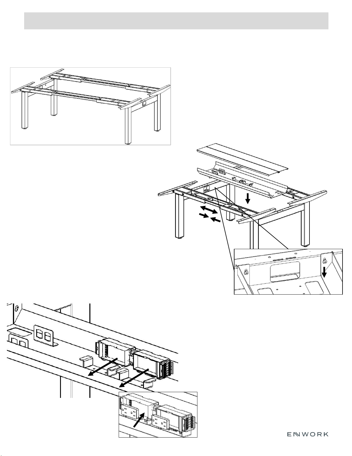
3.7.1) Double check that legs, frame, and links are tight.
**Note** Center rails to still be loose at this time.
3.7.2) With (at least) one other person, carefully flip
frame. Please note that the center rails will slide freely.
Fig 3.8
Fig 3.7
3.9.1) Attach power block to pre-installed brackets
as shown. Brackets should click into place.
3.9.2) Once power block is installed, insert the
outlets into place.
**Note** If wiring diagrams are needed, refer to
instructions from electrical components.
3.8.1) Loosely install (4) M6 x 1.0 Button head hex
screws into end and mid-links.
3.8.2) Lower power trough into place using
keyslots onto machine screws. Once it is in place,
secure all screws.
**Note** Center rails may need to slide to
accommodate for trough width.
3.8.3) After trough is in place, tighten all set
screws on the bottom of the frames to secure the
Center rails.
Standard Benching Cont.
Fig 3.9
Page 10
3) Assembly:
INSTALLATION GUIDE
10
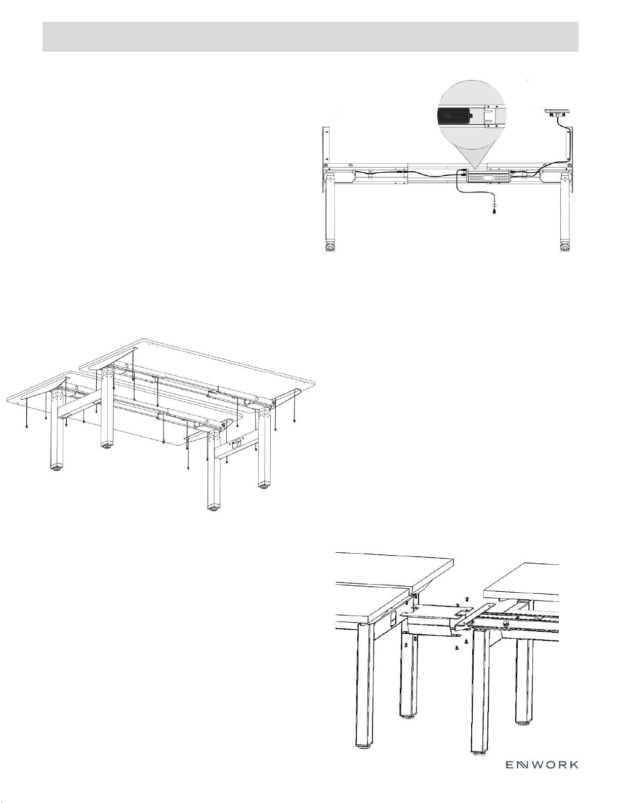
3.12.1) If attaching multiple pairs of desks, connect
them using the Mid-Link Connector and (8) M6 x
1.0 Button Head Hex Screws
Fig 3.12
3.11.1) Place worksurface(s) on top of frame.
3.11.2) Center surface so there is equal distance from
the front and back worksurface edges to the top
support arms.
3.11.3) Center surface so there is equal distance
from side to side of the worksurface edges to the
top support arms.
3.11.4) Attach worksurface to frame as shown, using
wood screws.
3.11.5) Attach Handset to underside of worksurface
using (2) wood screws.
**(Handset Instructions found near the end of this
instruction packet)**
Fig 3.11
3.10.1) Attach each control box to frame with
control pate. (See detail view in Fig. 3.9)
3.10.2) Connect the cables from the leg
columns to the control box via sockets labeled
‘M1’ and ‘M2’.
3.10.3) Connect the handset to the control box
via the socket labeled ‘HS’
3.10.4) Connect the power cable via the power
socket.
Fig 3.10
Standard Benching Cont.
Page 11
3) Assembly:
INSTALLATION GUIDE
11
Standard Benching Cont.
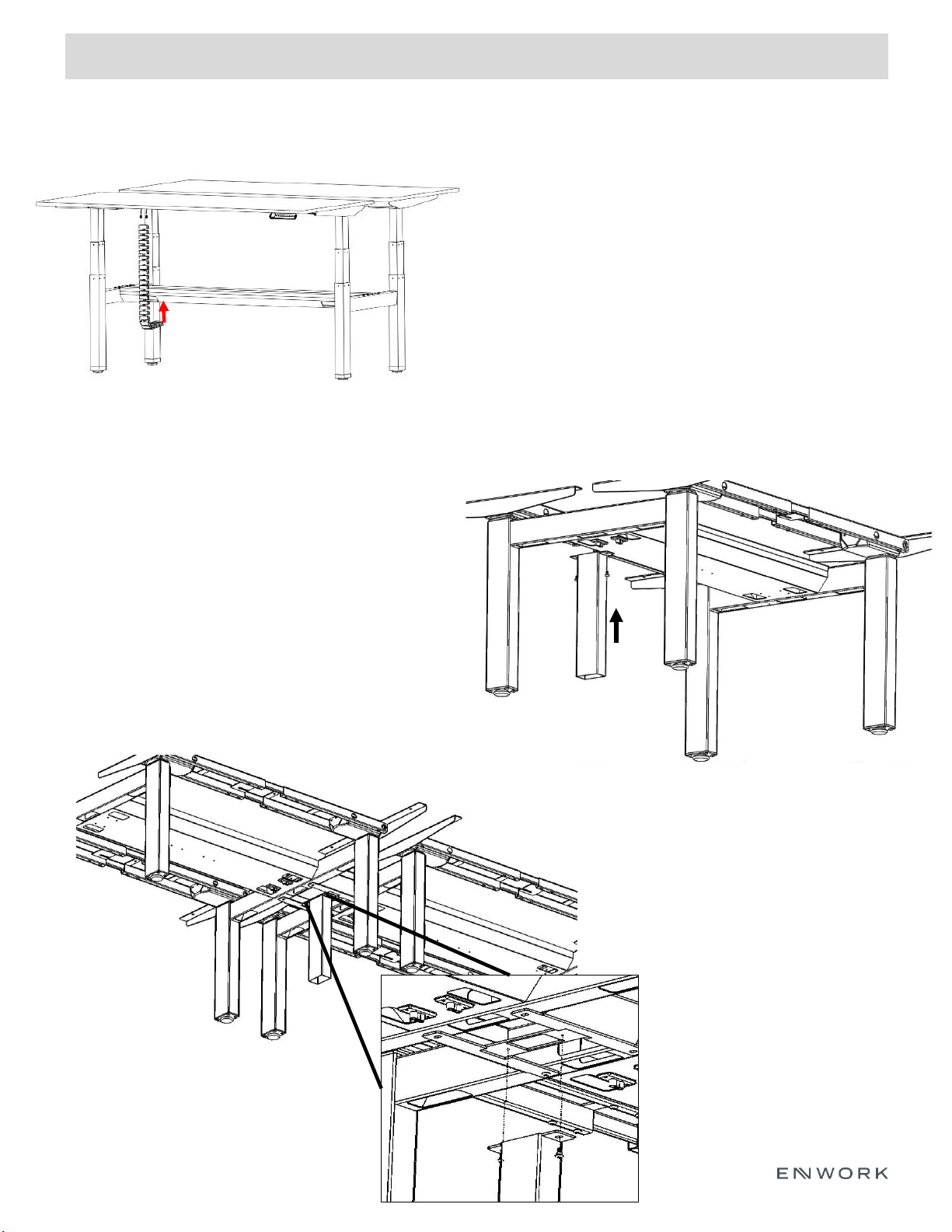
3.13.1) Attach a vertical cable manager to underside
of worksurface using (2) wood screws.
3.13.2) Run cables through the cable manager and
up through the bottom hole in the power trough.
Fig 3.13
Fig 3.15
Fig 3.14
3.14.1) Attach In-feed leg to bottom of link using
(2) M6 x 1.0 Button head hex screws.
3.14.2) Run power in-feed through this leg and
attach to power block in trough.
**Note** If multiple pairs of desk are used, attach In-Feed
leg to Mid Link Connector. See Fig 3.15 for detail
Page 12
4) Assembly:
INSTALLATION GUIDE
12
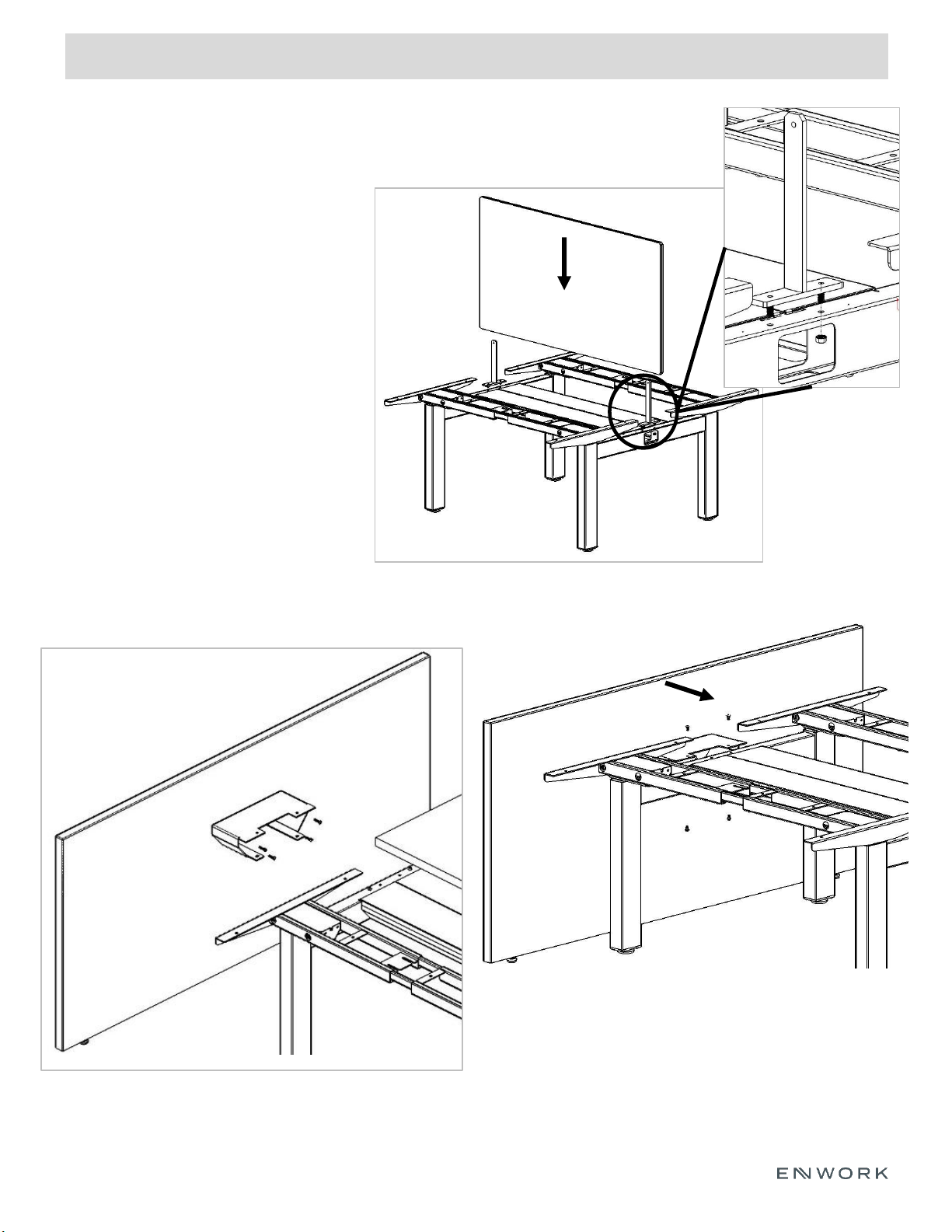
Fig. 4.2
4.1.1) Attach screen bracket to mid and
end links as shown using (4) M6 x 1.0
locknuts w/ external tooth lock washer.
Fully tighten.
**Note** If no screens are being used,
repeat this step using cover plates
instead of screen brackets
4.1.2) Slide screen down onto brackets
4.2.1) Attach end panel bracket to end panel using (4)
wood screws.
4.3.1) Slide end panel with attached bracket onto end
link as shown.
4.3.2) Attach end panel bracket to end link using (4)
M6 x 1.0 Button Head Hex Screws
Optional Additions
Fig 4.1
Fig 4.3
Page 13
5) Assembly:
INSTALLATION GUIDE
13
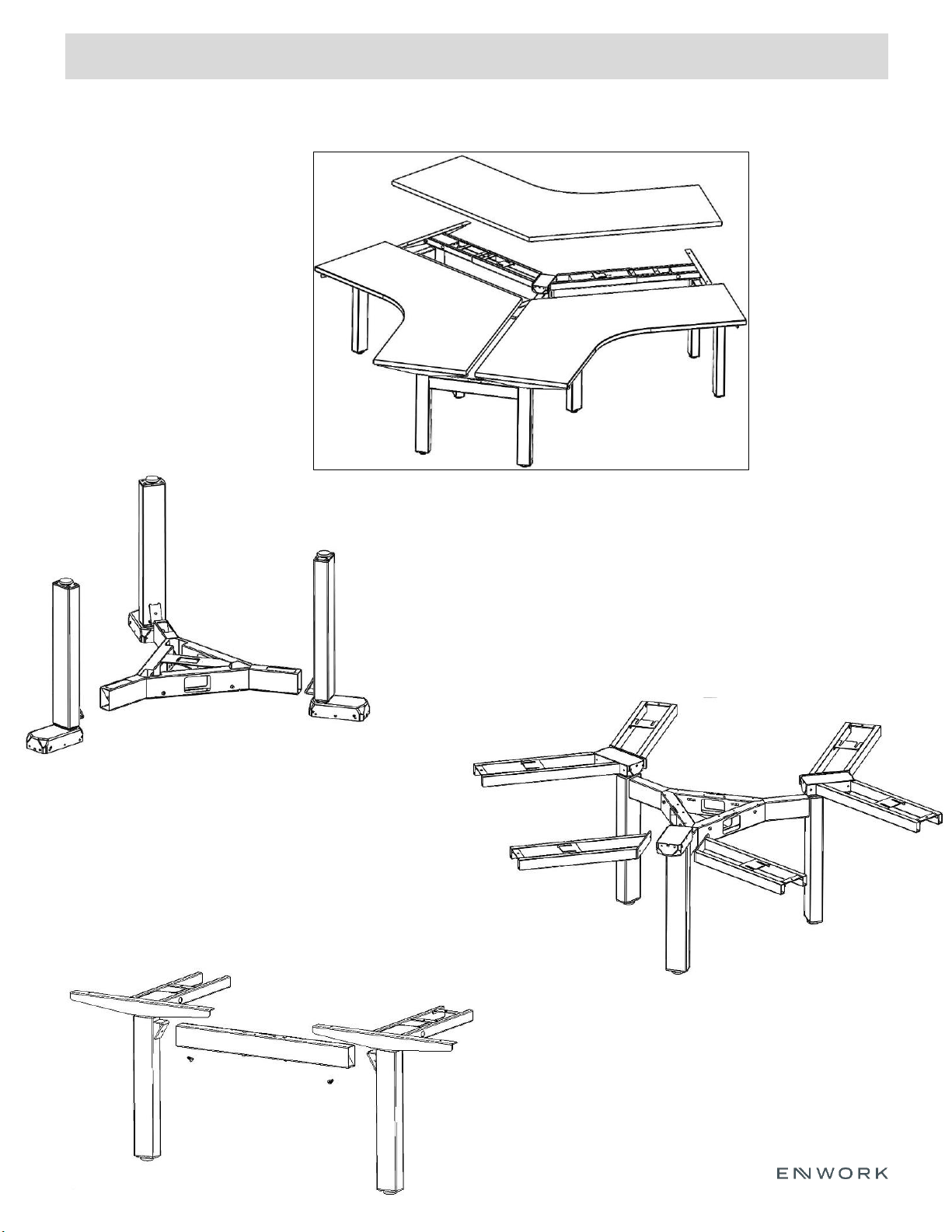
5.1.1) Attach (3) Rear Columns to 120
degree mid link using (1) M8 x 1.25 hex
head bolt per leg. Tighten
120 Degree Bench
Fig 5.1
5.2.1) Carefully flip base over and attach
frame ends with controls plates to rear
columns using (4) M6 x 1.0 Button head
hex screws per leg. Tighten.
5.3.1) Use (2) M8 x 1.25 Hex Head Bolts
to connect (1) End link to (1) Left Leg
Column and (1) Right Leg Column as
shown. Tighten.
Fig 5.2
Fig 5.3
3-Pack 120 Degree Shown
Page 14
5) Assembly:
INSTALLATION GUIDE
14
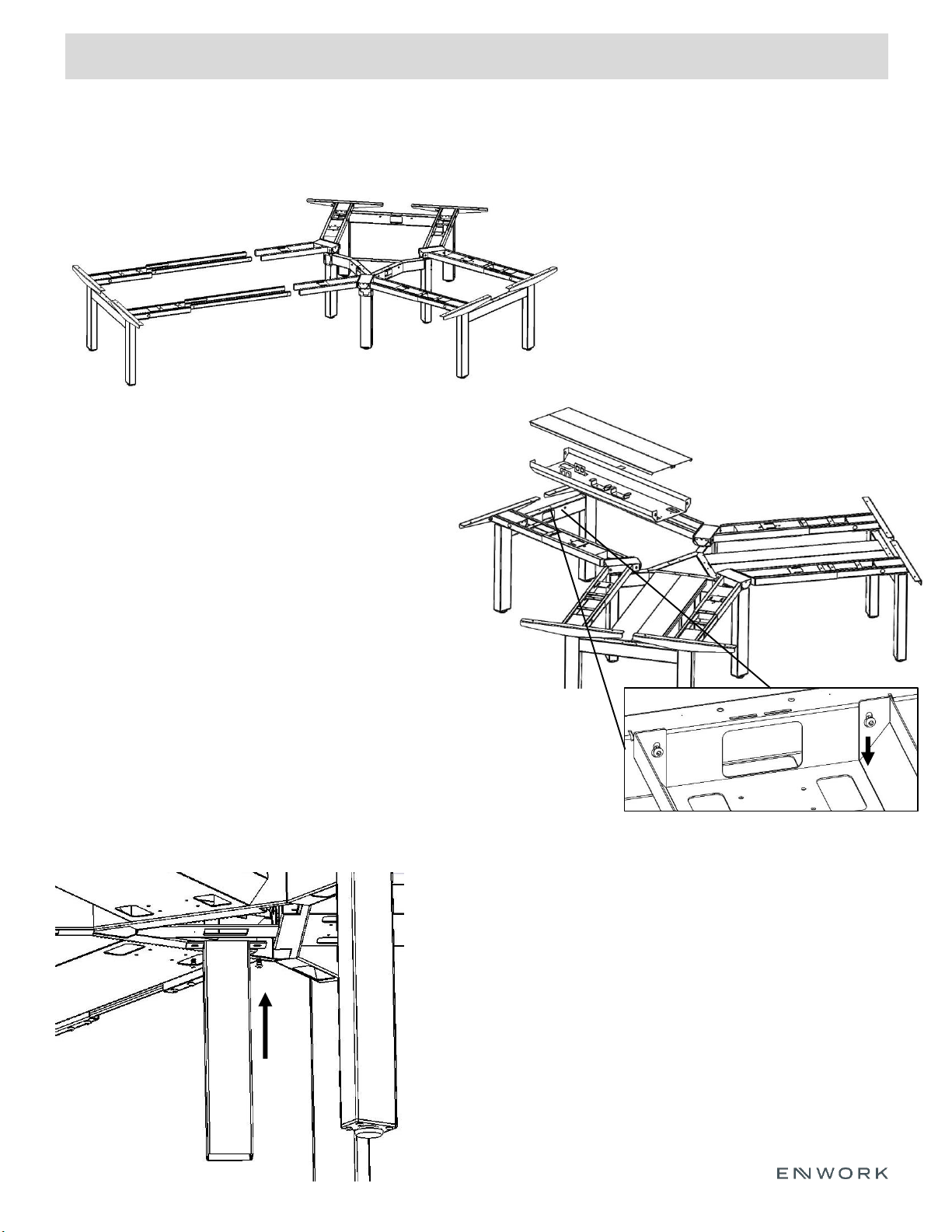
5.4.1) Using Center Rails, slide end assembly
and center assembly together as shown.
**Note** Set screws located on bottom of
frames may need to be loosened to allow
center rail to slide freely.
5.6.1) Attach In-feed leg to bottom of center triangle link
using (2) M6 x 1.0 Button head hex screws.
**Note** If multiple pairs of desk are used, In-Feed leg
may also be installed on the bottom of the Mid Link
Connector. See Fig 3.15 for detail
Fig 5.5
5.5.1) Loosely install (4) M6 x 1.0 Button Head
Hex Screws into end and center link per
power trough. Lower power trough into
place using keyslots onto machine screws.
Once it is in place, secure all screws.
**Note** Center rails may need to slide to
accommodate for trough width.
5.5.2) After trough is in place, tighten all set
screws on the bottom of the frames to secure
the Center rails.
Fig 5.6
120 Degree Bench Cont.
Fig 5.4
Page 15
5) Assembly:
INSTALLATION GUIDE
15
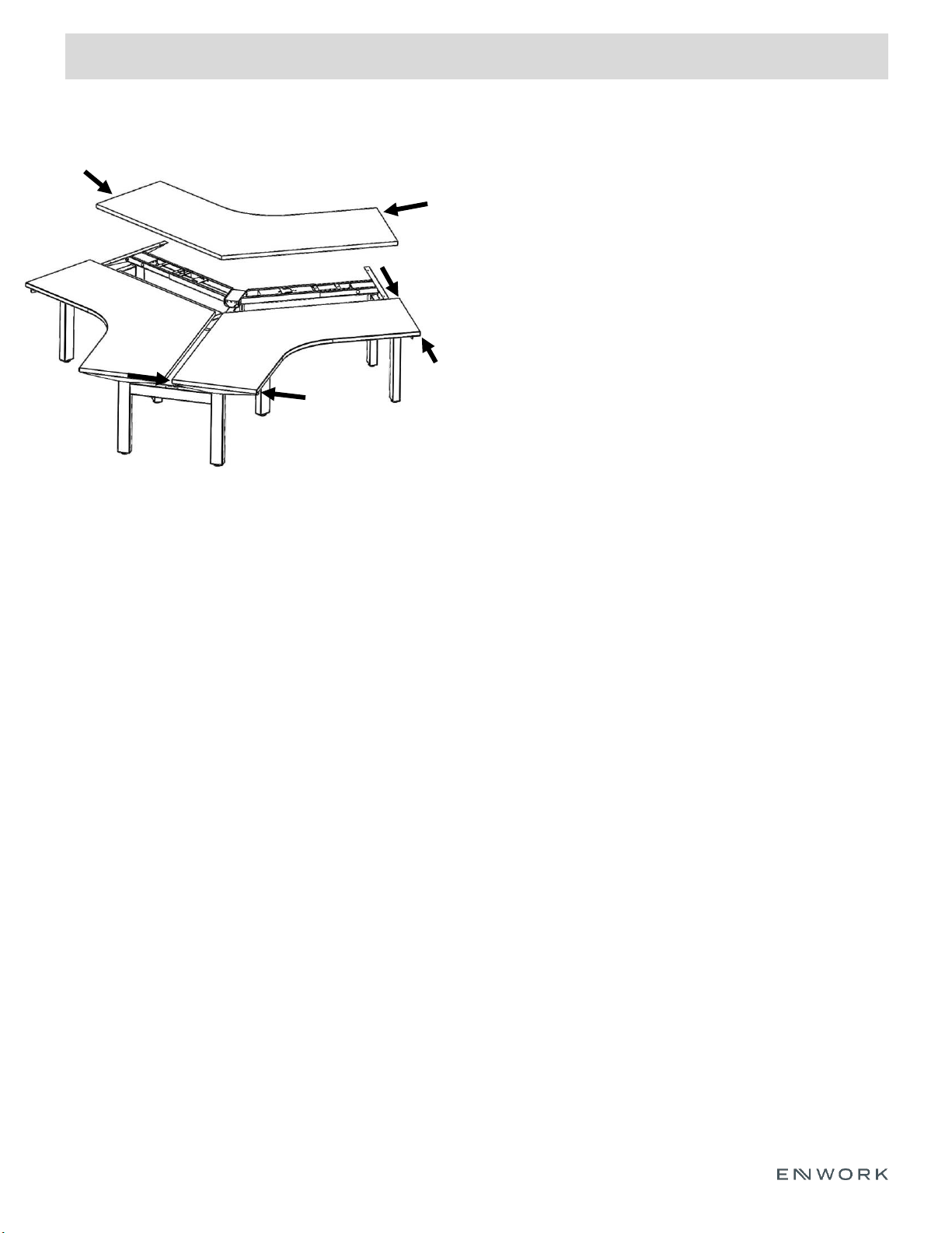
5.7.1) Place worksurface(s) on top of frame.
5.7.2) Center surface front to back using the flat
depths on each end shown as (d) to the left.
5.7.3) Center surface along the edges (w) so
there is equal overhang of the support arms on
each side.
5.7.4) Attach worksurface to frame, using wood
screws.
5.7.5) Once surface is attached, tighten all set screws
to fully secure center rails.
Fig 5.7
120 Degree Bench Cont.
d
d
w
w
d
d
Page 16
5) Assembly:
INSTALLATION GUIDE
16
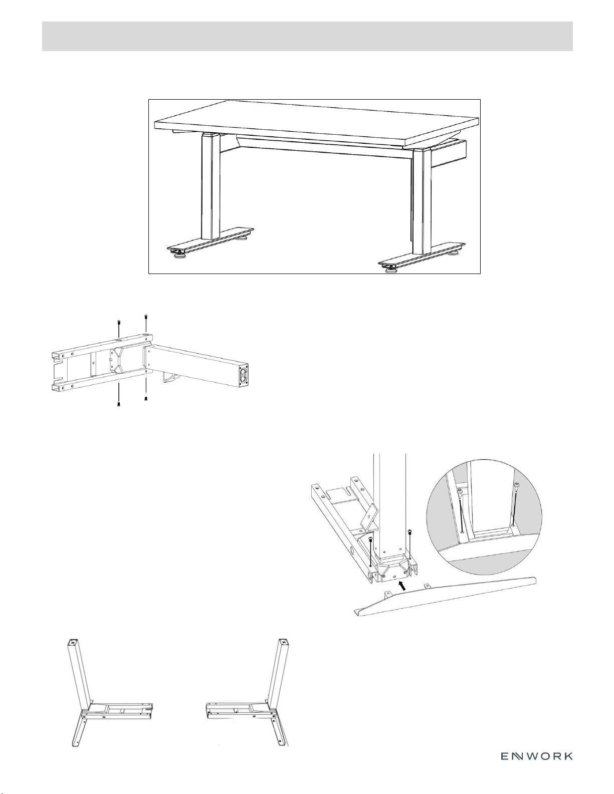
Fig 6.1
Fig 6.3
6.1.1) Insert a Right Leg Column into a Frame End w/ Control
Plate using (4) M6 x 1.0 Button head hex screws. Do not
fully tighten at this time.
Fig 6.2
Single Sided Bench
1 Pack Single Sided Unit Shown
6)
6.2.1) Attach a Top Support Arm using (2) M6 x 1.0
Button head hex screws. Do not full tighten.
6.2.2) Once Frame and Arm are in place together,
tighten all screws completely.
**Note** The two tabs on the support arm will slot
into the frame end, surrounding the leg column.
6.3.1) Repeat previous steps to assemble
remaining leg columns, frame ends, and top
support brackets.
Page 17
5) Assembly:
INSTALLATION GUIDE
17
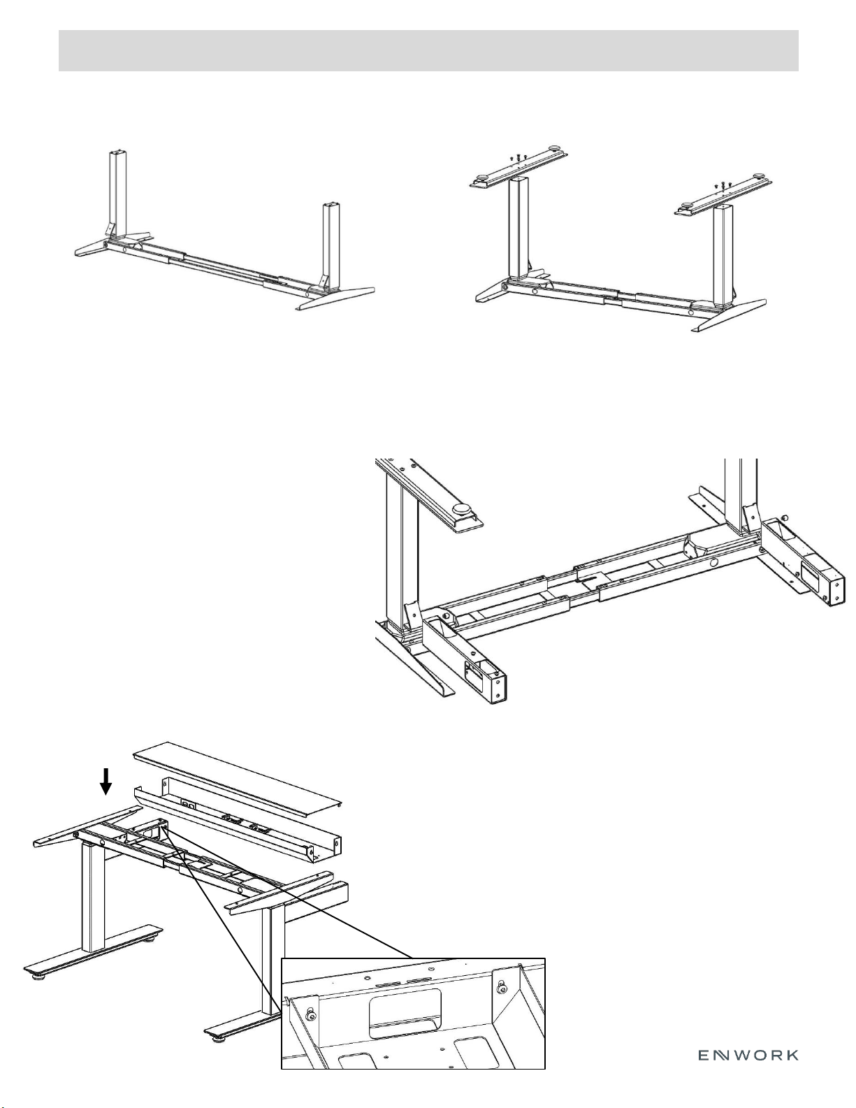
Fig 6.4
6.4.1) Using Center Rails, slide end assembly
and center assembly together as shown.
6.6.1) Use (2) M8 x 1.25 hex head bolts to
attach (1) End Link and (1) Mid Link to leg
columns as shown.
**Note** Mid-Link has a pass thru-hole.
End-Link will have one closed vertical face.
Use the Mid-link when additional desk pairs
are needed. Use the End-links where no
additional desks will be used.
Fig 6.6
Single Sided Bench Cont.
Fig 6.5
6.5.1) Use (8) M6 x 1.0 Hex Head Screws to
attach Feet to columns as shown. Tighten
Fig 6.7
6.71) With (at least) one other person, carefully flip
frame. Please note that the center rails will slide freely.
6.7.2) Loosely install (4) M6 x 1.0 Button Head Hex
Screws into end and mid-links. Lower power trough into
place using keyslots onto machine screws. Once it is in
place, tighten all screws.
6.7.3) After trough is in place, tighten all set screws on
the bottom of the frames to secure the Center rails.
**Note** Center rails may need to
slide to accommodate for trough width.
6)
Page 18
5) Assembly:
INSTALLATION GUIDE
18
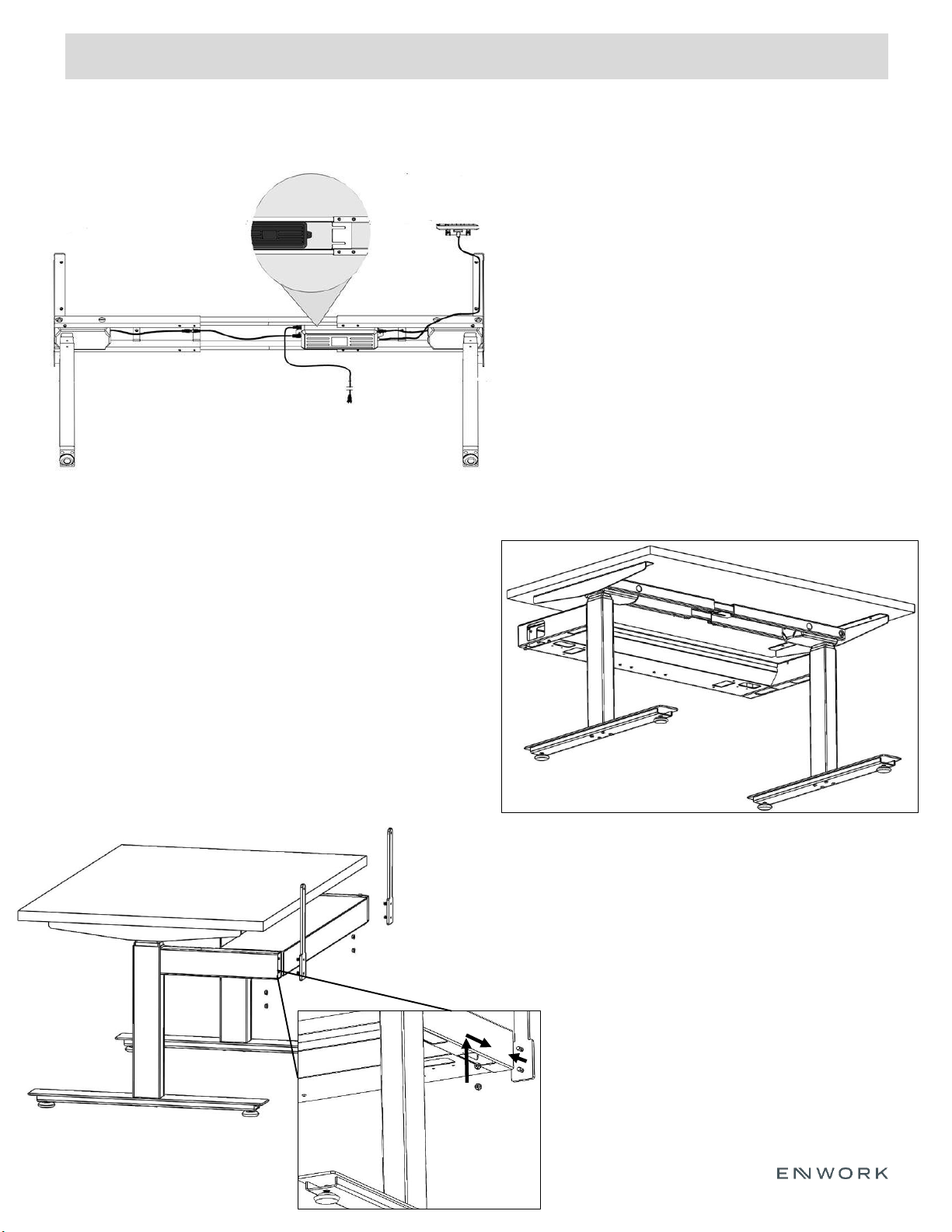
6.9.1) Place worksurface(s) on top of frame.
6.9.2) Center surface so there is equal
distance from the front and back worksurface
edges to the top support arms.
6.9.3) Center surface so there is equal
distance from side to side of the worksurface
edges to the top support arms.
6.9.4) Attach worksurface to frame using
wood screws.
Fig 6.9
Fig 6.10
Single Sided Bench Cont.
6.10.1) Attach screen bracket to mid and
end links as shown using (4) M6 x 1.0
locknuts w/ external tooth lock washer.
Fully tighten.
**Note** If no screen is being used, repeat
this step using cover plates instead of
screen brackets.
6.10.2) Slide screen down onto brackets
6.8.1) Attach each control box to frame with
control pate. (See detail view in Fig. 6.8)
6.8.2) Connect the cables from the leg
columns to the control box via sockets labeled
‘M1’ and ‘M2’.
6.8.3) Connect the handset to the control box
via the socket labeled ‘HS’
6.8.4) Connect the power cable via the power
socket.
Fig 6.8
6)
Page 19
5) Assembly:
INSTALLATION GUIDE
19
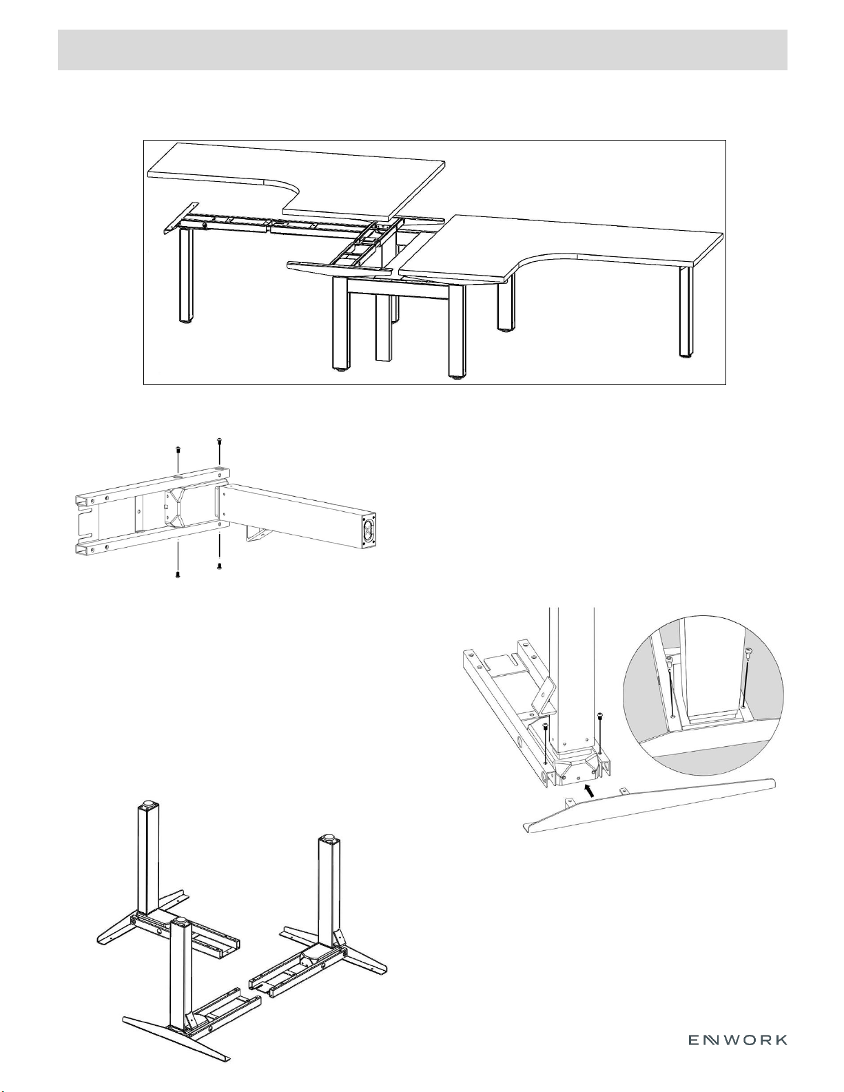
Extended Corner Bench
Fig 7.1
Fig 7.2
Fig 7.3
7.1.1) Insert a Right Leg Column into a Frame
End w/ Control Plate using (4) M6 x 1.0 Button
head hex screws. Do not fully tighten at this
time.
7.2.1) Attach a Top Support Arm using (2) M6 x 1.0
Hex Head Screws. Once both screws are in place,
tighten completely.
**Note** The two tabs on the support arm will slot
into the frame end, surrounding the leg column.
2 Pack Extended Corner Bench shown
7.3.1) Repeat previous steps for (1) Left
Leg assembly and (1) Extended Corner
Leg.
7)
Page 20
5) Assembly:
INSTALLATION GUIDE
20
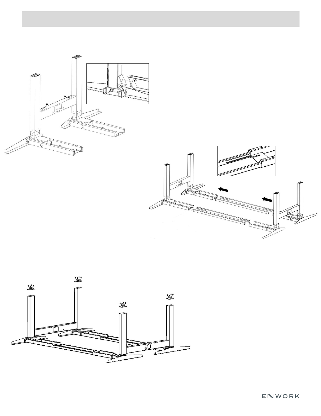
Extended Corner Bench Cont.
7.5.1) Slide center rail supports into leg assemblies
so that the midpoint mark is facing up and the slot-
cuts are facing inwards. Do not fully tighten set
screws at this step.
**Note** Orientation of center rail supports
7.4.1) Connect one Right leg assembly and one
Left leg assembly together using an End link and
(2) M8 x 1.25 Hex Head bolts. *See section detail
for alignment
7.4.2) Repeat previous step on left leg assembly
using a Mid link.
**Note** Mid-Link has a pass thru-hole. End-Link
will have one closed vertical face. Use the Mid-link
when additional desk pairs are needed. Use the
End-links where no additional desks will be used.
Fig 7.5
Fig 7.6
Fig 7.4
7.6.1) Attach each stand-off using (4) M6 x 1.0
Button Head Hex Screws.
7.6.2) Insert levelers if not already in place.
7)
Page 21
5) Assembly:
INSTALLATION GUIDE
21
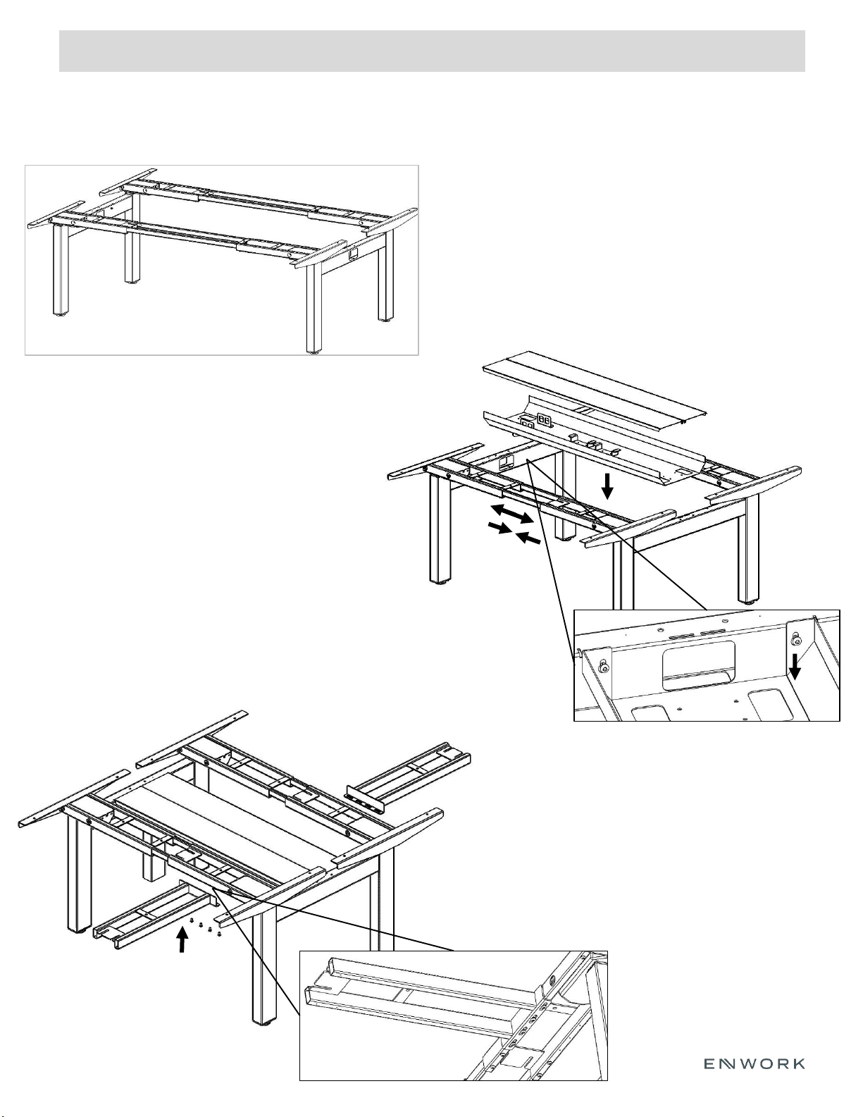
Extended Corner Bench Cont.
7.7.1) Double check that legs, frame, and links are tight.
**Note** Center rails to still be loose at this time.
7.7.2) With (at least) one other person, carefully flip
frame. Please note that the center rails will slide freely.
Fig 7.8
Fig 7.7
7.8.1) Loosely install (4) M6 x 1.0 Button Head Hex
Screws into end and mid-links.
7.8.2) Lower power trough into place using
keyslots onto machine screws. Once it is in place,
secure all screws.
**Note** Center rails may need to slide to
accommodate for trough width.
7.8.3) After trough is in place, tighten all set
screws on the bottom of the frames to secure the
Center rails.
7)
Fig 7.9
7.9.1) Loosely attach extended corner frame to
underside of benching frame using (4) M6 x
1.0 Button Head Hex Screws.
Page 22
5) Assembly:
INSTALLATION GUIDE
22
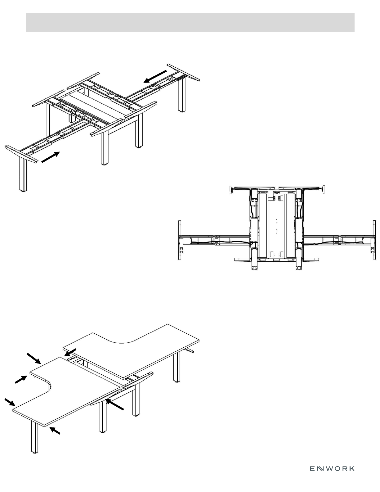
Extended Corner Bench Cont.
7.10.1) Using the center rails, slide extended corner leg
assembly on the extender corner frame.
**Note** Center rails and extended corner frame to still
be loose at this time.
Fig 7.11
Fig 7.12
Fig 7.10
7.11.1) Attach each control box to frame with
control pate. (See detail view in Fig. 3.9)
7.11.2) Connect the cables from the leg
columns to the control box via sockets labeled
‘M1’, ‘M2’, AND ‘M3’.
7.11.3) Connect the handset to the control box
via the socket labeled ‘HS’
7.11.4) Connect the power cable via the power
socket.
7.12.1) Place worksurface(s) on top of frame.
7.12.2) Center surface along the spine of the bench
(w) so there is equal overhang of the support arms
on each side.
7.12.3) Center surface front to back using the flat
depths shown as (d) to the left.
**Note** The extended corner frame has slotted holes
to allow for frame adjustment based on surface size
7.12.4) Once centered, attach worksurface to frame
using wood screws.
7.12.5) Attach Handset to underside of worksurface
using (2) wood screws.
7.12.6) Tighten all set screws on center rails and
extended corner frame.
**(Handset Instructions found near the end of this
instruction packet)**
d
d
w
w
d
d
7)
Page 23

5) Assembly:
INSTALLATION GUIDE
23
Initial calibration
Before you start using your desk normally, you’ll need to get all the parts synced. Based on your
handset, follow the instructions below.
With Standard Up-Down Handset
1. Press and hold the DOWN button until the desk reaches its lowest position. Release.
2. Press and hold the DOWN button again for about 10 seconds. Release.
3. Press and hold the DOWN button again, this time until the desk first lowers slightly, then rises
slightly, and finally stops. Release the DOWN button.
You’re all set.
With Memory Preset Handset
1. Press and hold the DOWN button until the display reads RST. Release.
2. Press and hold the DOWN button again, this time until the desk first lowers slightly, then rises
slightly, and finally stops. Release the DOWN button.
You can now use your desk. See pages 24-25 for tips on making the most of your Memory Preset
Handset.
Setting memory presets
1. Adjust the desk to the desired height.
2. Press M (the display will show S -).
3. Press a number 1 – 4.
4. Pressing that number will return your desk to the programmed height. By default, the desk will
continue to move on its own once you’ve activated the preset, though pressing any other button
will stop this movement. If you prefer to change this behavior, please refer to “Toggle between
One Touch and Constant Touch Presets” on page 26.
Operating Setup
Page 24

5) Assembly:
INSTALLATION GUIDE
24
Lock your desk
If you have a Memory Preset handset, your desk can be locked in place at any height, either as a safety
precaution or just to keep your friends from messing with your settings. It unlocks just as easily, but we
recommend guarding that secret.
To lock: Press and hold the M button for about 8 seconds. The display will first change to ‘S –’, then to
‘LOC’, indicating that the desk is now locked.
To unlock: Press and hold the M button for about 8 seconds until ‘LOC’ goes away and the height
appears on the display.
Adjust the height readout
Our LED handsets display the approximate height of your desk top surface, in inches or centimeters.
The accuracy may be affected by the thickness of your top, the evenness of your floor, etc. If you want
it to be completely accurate, you can manually set the readout to match your measured height.
1. Press and hold the DOWN button until the desk reaches its lowest position. Release.
2. With a tape measure, measure the distance from the floor to your desk top surface. If it matches
your readout, you’re all set. Otherwise, proceed to the next step.
3. Press and hold the DOWN button again, until the display flashes RST (looks like “AS Γ”). Release.
4. Press and hold the M button until it begins to flash the starting height. Note: the display will revert
to RST after about 5 seconds. If that happens before you have a chance to make your changes, just
press and hold M again.
To change the readout height:
5. Use the UP or DOWN button to adjust the display by 0.1 inch at a time until the display shows the
correct height, as measured.
6. Wait about 5 seconds and the display will automatically return to RST, which indicates Reset Mode.
7. Complete the reset process by pressing and holding the DOWN button again while the desk lowers
a little bit more, slightly rises, and then stops.
8. Release the button, and you should see the new starting height ±.1 inches. This height is saved, and
your desk is ready to use!
Set custom upper and lower height limits
By default, the frame and handset are set to allow the maximum range of motion, from a retracted
Lifting Column, to an extended one. If you would like to set a higher minimum height or a lower
maximum height, you can do that! Before starting, make sure the desk is plugged in, and the LED
display is showing a number. If the readout has gone dark, you can wake it up by pushing any button.
If it is displaying something besides a number, perform the Reset Procedure on page 27.
Custom Settings for Preset Memory Handset
Page 25

5) Assembly:
INSTALLATION GUIDE
25
Set custom upper and lower height limits continued
To set the upper limit:
1. Use the UP/DOWN buttons to move the desk to the desired maximum height.
2. Press the M button and release, then press the UP button and release. The display will flash S - to
show that it is ready to set the upper limit.
3. Press and hold the M button for about 2 seconds. The display will show “999” and then return to
the height readout. This indicates that the upper limit is set. All done!
To set the lower limit
1. Use the UP/DOWN buttons to move the desk to the desired minimum height.
2. Press the M button and release, then press the DOWN button and release. The display will flash S –
to show that it is ready to set the lower limit.
3. Press and hold the M button for about 2 seconds. The display will show “000” and then return to
your selected height. This indicates that the lower limit is set. You did it!
Warning: There are certain times when your desk might require a Reset Procedure to correct a balance,
calibration or other issue. This procedure requires the legs to retract completely, beyond any lower
height limits that might be set. Please ensure that you have the proper clearance below the desk base.
Note: If you had previously set any memory presets that were outside of your newly defined range,
they won’t work anymore. You can reuse the numbers.
2nd Note: If you want to set a new upper or lower limit that is outside of your set range, you will first
have to restore the defaults.
To restore default upper and lower limits
1. Press the M button and release. “S -” will appear on the display.
2. Within 5 seconds, press the M button again and hold for about 2 seconds until the display shows
“555”.
3. Release the button. The display will automatically change back to the height display, and your
height limits will reset.
Custom Settings for Preset Memory Handset cont.
Page 26

5) Assembly:
INSTALLATION GUIDE
26
Custom Settings for Preset Memory Handset cont.
Toggle between One Touch and Constant Touch presets
Our programmable handsets allow your desk to remember your favorite height settings. By default, if
you press and release a memory preset button, the desk will move on its own to the programmed
height. You can change this behavior so that the desk will only continue to move to the programmed
height with continued pressure on that preset number. Here’s how to toggle this setting:
1. Press and hold the DOWN button until the desk reaches its lowest position. Release.
2. Press and hold the DOWN button again, until the display begins to flash RST (looks like “ASΓ”).
3. With the display still flashing RST, press and hold the 1 button for about 5 seconds. The handset will
register the change in input method and display the corresponding readout
10.1 = One Touch
The desk will keep moving to the preset height after you release the memory preset button
10.2 = Constant Touch
The desk will only continue to the programmed height while you are holding the corresponding preset
button
4. To toggle to the next setting, press and hold the 1 button again for 5 seconds, until the displayed
readout updates.
5. Once your preferred setting displays, release the button and wait about 5 seconds for the display to
return to RST.
6. Complete the reset process by pressing and holding the DOWN button again while the desk lowers
a little bit more, slightly rises, and then stops. Release the button. Your new preset touch setting is
saved, and the desk is ready to use!
Change readout between inches and centimeters
By default, our programmable handsets display inches on models configured for 120-Volt power, and
centimeters on models for 240-Volt power. If you’d like to break with tradition, you can easily change
this setting.
1. Press and hold the DOWN button until the desk reaches its lowest position. Release.
2. Press and hold the DOWN button again, until the display begins to flash RST (looks like “ASΓ”).
3. Press and hold the 2 button for about 5 seconds. Your handset will register the unit change and
display the corresponding readout:
10.3 = Centimeters 10.4 = Inches
4. To toggle to the next setting, press and hold the 2 button again for 5 seconds, until the displayed
readout updates.
5. Once your preferred setting displays, release the button and wait about 5 seconds for the display to
return to RST.
6. Complete the reset process by pressing and holding the DOWN button again while the desk lowers
a little bit more, slightly rises, and then stops. Release the button. Your preferred unit setting is now
saved, and the desk is ready to use!
Page 27

5) Assembly:
INSTALLATION GUIDE
27
Troubleshooting
*If your desk is not functioning properly, or if you have a Memory Preset Handset that reads “RST” or
any error message (E01 - E13), confirm that all wired connections are secure (legs to cables, cables to
Control Box). Once you’re certain that all connections are secure, perform the reset procedure below. If
the error message persists after the reset procedure, contact 800-815-7251.
*If there is a difference in height between the two legs that exceeds 1.5”, stop the reset procedure and
contact 800-815-7251.
*If the Memory Preset Handset displays “HOT”, let the desk cool down for 20 minutes.
Reset procedure
CAUTION: This will override any custom lower limit you might have set! Please ensure proper
clearance for the Lifting Columns to retract.
With Standard Up-Down Handset
1. Press and hold the DOWN button until the desk reaches its lowest position. Release.
2. Press and hold the DOWN button again, for about 10 seconds. Release.
3. Press and hold the DOWN button again, this time until the desk first lowers slightly, then rises
slightly, and finally stops. Release the DOWN button.
You’re all set!
With Memory Preset Handset
1. Press and hold the DOWN button until the desk reaches its lowest position. Release.
2. Press and hold the DOWN button until the display reads RST. Release.
3. Press and hold the DOWN button again, this time until the desk first lowers slightly, then rises
slightly, and finally stops. Release the DOWN button.
You can now use your desk!
Troubleshooting & Reset
Page 28

12900 Christopher Drive Lowell, MI 49331
800.815.7251 www.enwork.com
Specifications subject to change without notice.
28
 Loading...