

Sliding Top Desk
Sliding Top Desk
AMI0004 - Installation Instruction
Revision A 12/14/2017

1) Parts and Fasteners Included
INSTALLATION GUIDE
AMM-3030-xx QTY: (1)
BOLTED FRAME ASSEMBLY
AMM-1424-xx QTY: (1)
TROUGH
LVTER QTY: (2)
LEG COLUMN ASSEMBLY
AMM-1425-2 QTY: (1)
WIRE MANAGEMENT COVER
EM-2162-3 QTY: (2)
FOOT WELDMENT
AMM-1433-2 QTY: (4)
SLIDING/STOP BRACKET
FOOT ATTACHMENT QTY: (2)
SPACER
AML-1354-xx QTY: (1)
WORK SURFACE BACK PIECE
AML-1355-xx QTY: (1)
WORK SURFACE FRONT PIECE
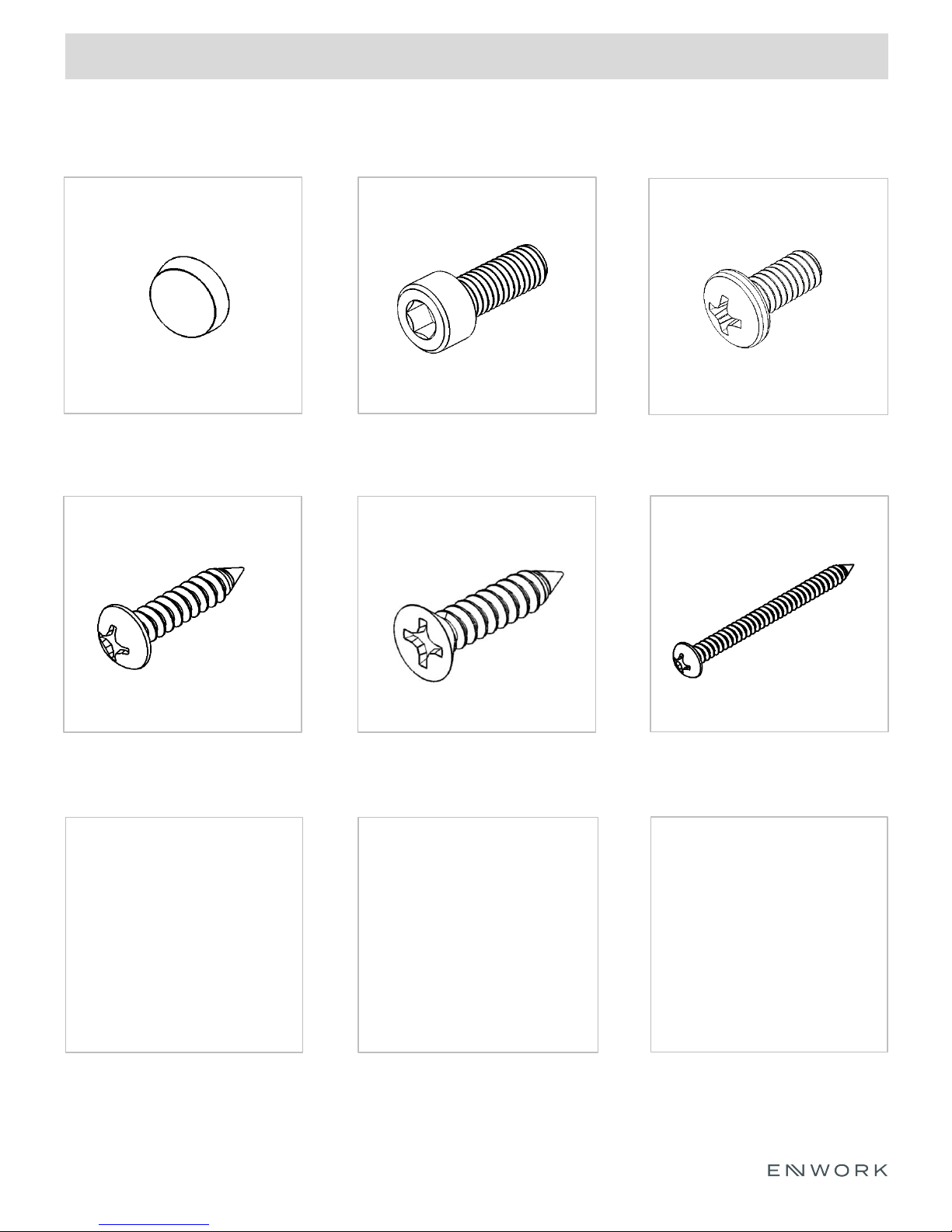
1) Parts and Fasteners Included
INSTALLATION GUIDE
3M BUMPON ADHESIVE
BACKED RUBBER BUMPER
QTY: (2)
#8 x 0.75” PAN HEAD WOOD SCREW
QTY: (12)
M6 X 16mm SHCS
QTY: (20)
#8x 0.75” FLAT HEAD WOOD SCREW
QTY: (4)
#8-32 x .375” MACHINE SCREW
QTY: (11)
#10 x 2.25” WOOD SCREW
QTY: (6)
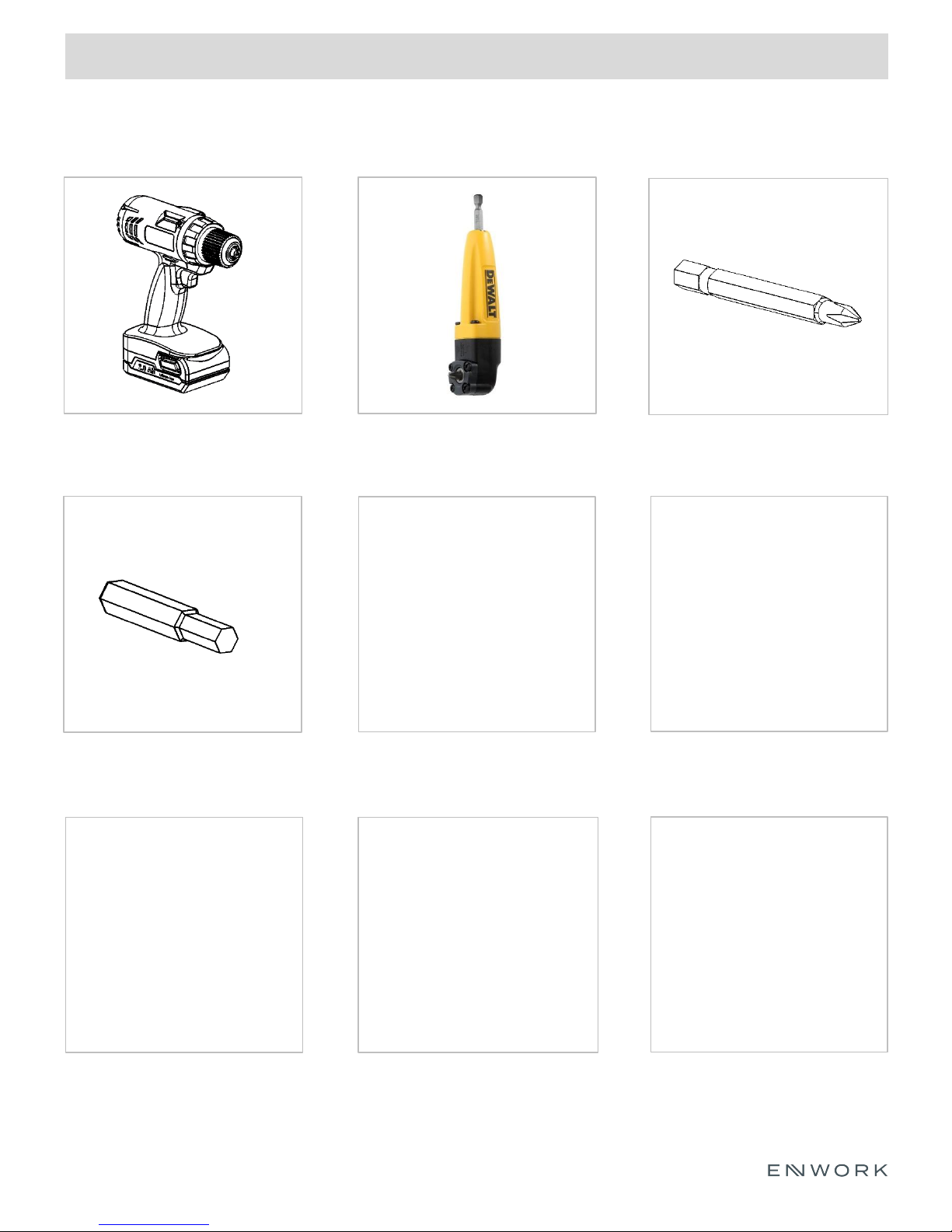
2) Tools and Supplies Required
INSTALLATION GUIDE
DRILL / DRIVER
5mm HEX BIT
RIGHT ANGLE DRILL ADAPTER
#2 PHILLIPS DRIVER BIT
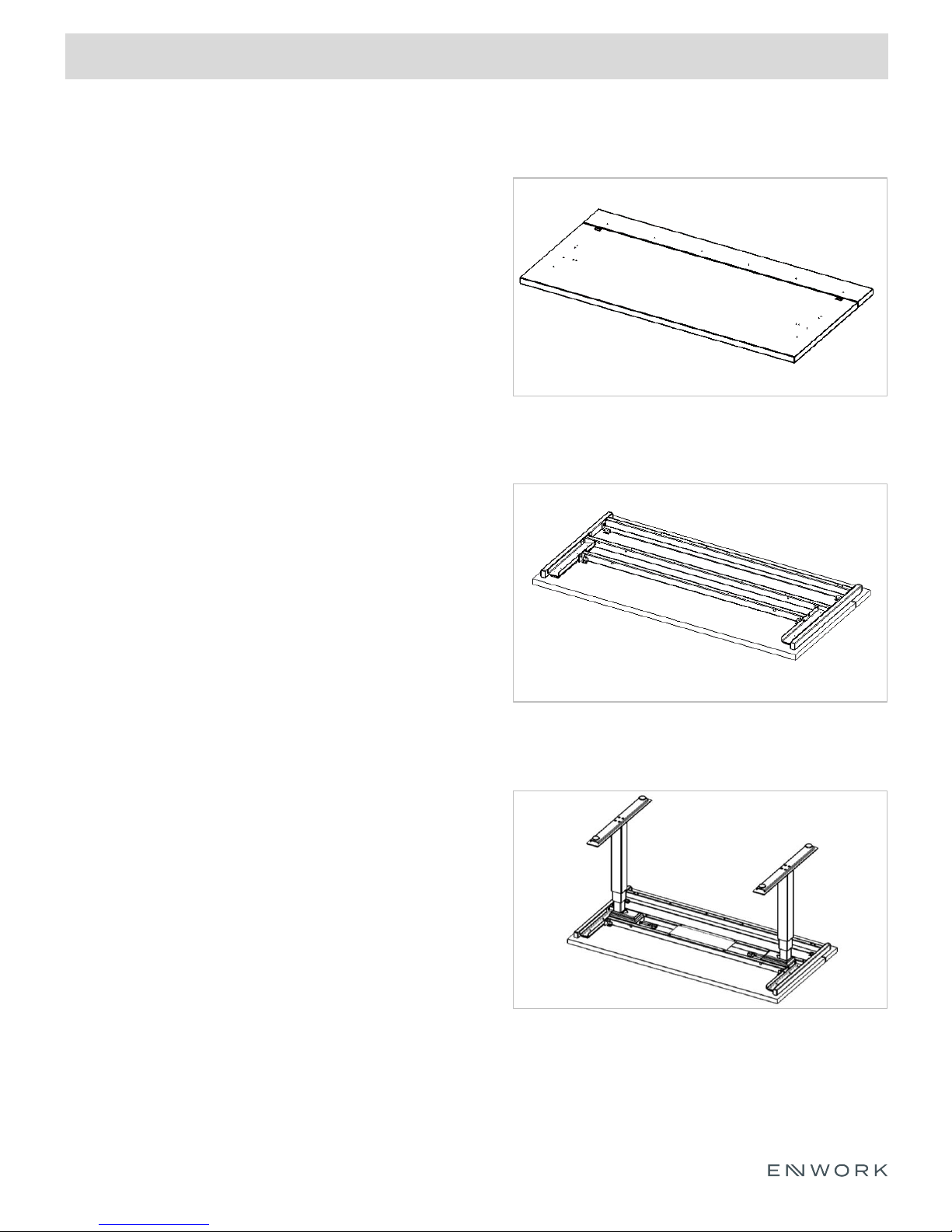
3) Assembly Overview
1. Surface preparation
2. Bolted frame attachment
3. Leg column attachment
4. Slide-stop bracket attachment
INSTALLATION GUIDE
5. Trough attachment
6. Foot attachment
7. Handset Attachment
8. Wire Management
9. Completed Table
FIGURE 3.1
WORKSURFACE
FIGURE 3.3
BOLTED FRAME ATTACHMENT
FIGURE 3.6
LEG AND FOOT ATTACHMENT
INSTALLATION GUIDE
4) Assembly:
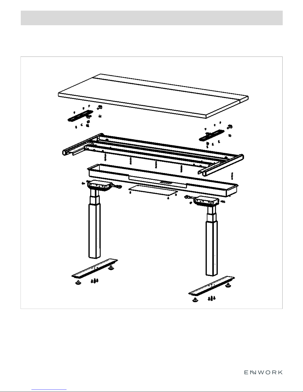
Exploded View
FIGURE 4.0.1
EXPLODED ASSEMBLY VIEW

INSTALLATION GUIDE
4) Assembly:
FIGURE 4.1.1
Work-surface preparation
Place both work-surface pieces (AML-1354-xx
and AML-1355-xx) down on a padded
workbench or similar non-marring surface.
Bolted Frame Attachment
Figure 4.2.1
Bolted frame attachment
Line up the predrills of the work-surface back
piece (AML-1354-xx) to the through holes of
the Bolted Frame Assembly (AMM-3030-xx).
Attach the Bolted Frame Assembly (AMM3030-xx) to the work-surface (AML-1354-xx)
using (6) #10 x 2.25” wood screws.
FIGURE 4.2.2
Top view of work surface and bolted frame
shown.
FIGURE 4.2.3
Detailed view of figure 4.2.2 shown.
After AMM-3030-xx is attached, confirm that
the product matches the picture shown in
Figure 4.2.3.

INSTALLATION GUIDE
4) Assembly:
Figure 4.2.4
Bolted Frame Attachment Cont.
Open the drawer slides (6500B 14) and line up the
predrills to the circular holes in the drawer slide.
Attach the drawer slides to the work-surface sliding
piece (AML-1355-xx) using (8) #8 x 0.75” Pan head
wood screws.
Detailed view of slide attachment.
Note: The center attachment point may be covered by
the middle slide rail. Adjust the slide accordingly to
access this attachment point.
Figure 4.2.5
Figure 4.2.6
Once the slides are attached, slide the desk back to
the closed position.
Once the drawer slides are attached to the work
surface sliding piece, slide the top into the closed
position.

INSTALLATION GUIDE
4) Assembly:
Leg Column Attachment
Figure 4.3.1
To attach the leg columns to the bolted frame, insert (2) M6 x 16mm socket head cap screws into the
threaded holes in the back of the leg column. Do not fully drive these screws in, simply get them started into
the threaded holes.
Then, lower the leg column down onto the bolted frame so that the partially inserted screws rest on the
open notches of the bolted frame assembly.

INSTALLATION GUIDE
4) Assembly:
Figure 4.3.2
Leg Column Attachment Cont.
Detailed view of previous step shown.
The bolts will rest in the open slot cuts of the Bolted
Frame assembly.
Line up the clearance holes in the bolted frame with
the threaded holes in the side of the leg column.
Attach the leg column to the bolted frame with (4) M6
x 16mm socket head caps screws.
Figure 4.3.3
Figure 4.3.4
NOTE: If the front crossbar of the Bolted frame
assembly does not line up to the leg column, loosen
the 1/4-20 Phillips pan head screw that holds the front
crossbar to the slide plate. This will allow the Leg
column to seat flush to the front crossbar. Tighten the
¼-20 pan head screw when finished.
Fully tighten the (2) M6 bolts from Figure 4.3.1
Repeat steps from Figure 4.3.1 through 4.3.4 for the
second leg column.

INSTALLATION GUIDE
4) Assembly:
Figure 4.4.1
Slide-Stop Bracket Attachment
Locate the two slide stop brackets (AMM-1433-2) that
do not have magnets attached to them.
Locate (4) #8 x 0.75” flat head wood screws.
Attach the slide stop bracket to the designated
pockets routed into the front work surface using (2) #8
x 0.75” flat head wood screws.
Verify that the bracket is orientated correctly as seen in
figure 4.4.2.
Figure 4.4.2
Figure 4.4.3
Locate the 3M Bumpon adhesive bumper.
Peel the bumper off of the backer paper and attach it
to the front of the slide-stop bracket. Center the
bumper over the small hole in the bracket.
Complete the above steps for the second bracket.

INSTALLATION GUIDE
4) Assembly:
Figure 4.4.4
Slide-Stop Bracket Attachment Cont.
Locate (2) Slide-stop brackets with the magnets
attached and (4) #8 x 0.75” Pan head wood screws.
Confirm that the sliding top is in the closed position.
Place the Slide-stop bracket on the work surface and
align the clearance slots with the pre-drilled holes in
the work surface.
Allow the magnet to attach to the front crossbar of the
Bolted Frame assembly. Verify that the clearance slots
still line up with the pre-drilled holes.
Figure 4.4.5
Figure 4.4.6
Attach the Slide-stop bracket to the work surface using
(2) #8 x 0.75” Pan head wood screws.
Complete the above steps for the second Slide-stop
bracket.

INSTALLATION GUIDE
4) Assembly:
Trough Attachment
Figure 4.5.1
Locate the wire management trough (AMM-1424-xx).
Align the clearance holes in the trough with the threaded holes in the Bolted Frame assembly. The larger
clearance holes will also align with the heads of the screws from Figure 4.2.2
Attach the Trough with (7) 8-32 x 0.375” Pan head machine screws.

INSTALLATION GUIDE
4) Assembly:
Foot Weldment Attachment
Locate the Foot Attachment Spacer.
Place the Foot Attachment Spacer on the bottom of the Leg column. Align the 4 holes in the Foot Spacer
with the tapped holes in the Leg column.
Locate the Foot Weldment (EM-2162-3) Align the clearance holes in the Foot Weldment to the clearance
holes in the Attachment Spacer.
Attach the Foot Weldment to the leg column using (4) M6 x 16mm socket head cap screws.
Repeat these steps for the second Attachment Spacer and Foot Weldment.
Figure 4.6.1

INSTALLATION GUIDE
4) Assembly:
Figure 4.7.1
Handset Attachment
Locate the electronics included with the Leg columns
(LVTER).
Refer to the assembly instructions included in the Leg
Column box for information on assembling the
electronics of the base.
Once the electronics are properly assembled, place the
power supply block in between the crossbars of the
Bolted Frame assembly.
NOTE: Do not attach the power supply block to the
work surface with screws as this will cause the sliding
work surface to malfunction.
Figure 4.7.2
Figure 4.7.3
Attach the included handset to the front edge of the
sliding work surface.
Be sure to leave enough slack in the handset cord to
allow the top to travel back and forth.

INSTALLATION GUIDE
4) Assembly:
Figure 4.8.1
Wire Management Cover Attachment
Locate the Wire Management Cover (AMM-1424-x)
and (4) 8-32 x 0.375” pan head machine screws.
Align the clearance holes in the Wire Management
Cover with the tapped holes in the Bolted Frame
assembly
Attach the Wire Management Cover with (4) 8-32 x
0.375” pan head machine screws.
Figure 4.8.2
Verify that no wires are pinched between the Power
Supply Cover and the work surface.

INSTALLATION GUIDE
4) Assembly:
Completed Table
Carefully flip the desk over onto the feet. Adjust the glides as needed to level the desk.
FIGURE 4.9.1

12900 Christopher Drive Lowell, MI 49331
800.815.7251 www.enwork.com
Specifications subject to change without notice.
 Loading...