

Page 1
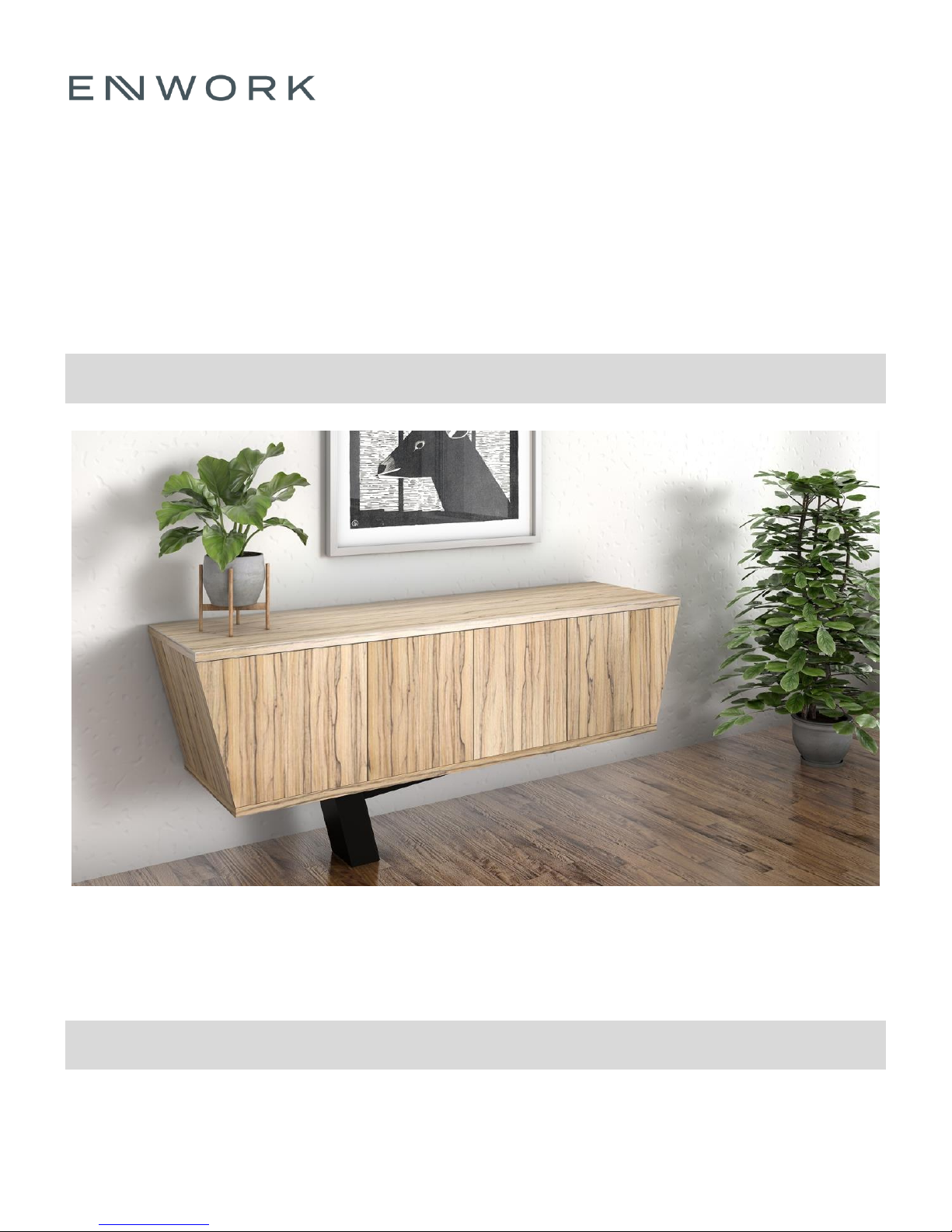
Equilibrium Credenza
EI0006 – Revision A – 8/20/18
Cantilevered base & Tapered Credenza
Installation Instruction
Page 2

12900 Christopher Drive Lowell, MI 49331
800.815.7251 www.enwork.com
Specifications subject to change without notice.
Equilibrium End User Agreement
Enwork Equilibrium credenza bases must be installed directly onto a four inch
minimum thickness concrete floor using factory provided hardware.
Warning and Indemnity Agreement
Failure to install on four inch thick concrete floor or failure to follow installation
instructions may cause table to function improperly and could lead to personal
injury and or structural damage. Do not, under any circumstance, install on a
concrete floor less than four inches thick.
Equilibrium credenza assembled can weigh over 400 pounds (unloaded)
supported in 0.167 square foot area. It is the responsibility of the dealer to verify
that the location for Equilibrium is suitable and is properly installed. End user
agrees that the installation shall not be modified and the location of the table
base shall not be moved without assistance from an Enwork Dealer.
It is the responsibility of the dealer and end user to adhere to and follow any
local or state building, electrical and accessibility codes.
Enwork is not responsible for any structural failures or personal injuries or
property damage due to improper installation or improper use of product. End
user agrees to defend, indemnify and hold harmless Enwork from any claims of
any nature or type arising out of unauthorized modification or movement of the
table base or any other improper use of the product.
Note: Installation requires at least two people.
Page 3

1) Tools and Supplies Required
INSTALLATION GUIDE
Hammer or Mallet
Tape Measure
Drill / Hammer Drill
½” Diameter
Masonry Drill Bit
Adjustable Wrench
Socket Wrench
3/4” Socket
Level
Square Drive
Utility Knife
Marker
Roll of Tape
Vacuum
Page 4
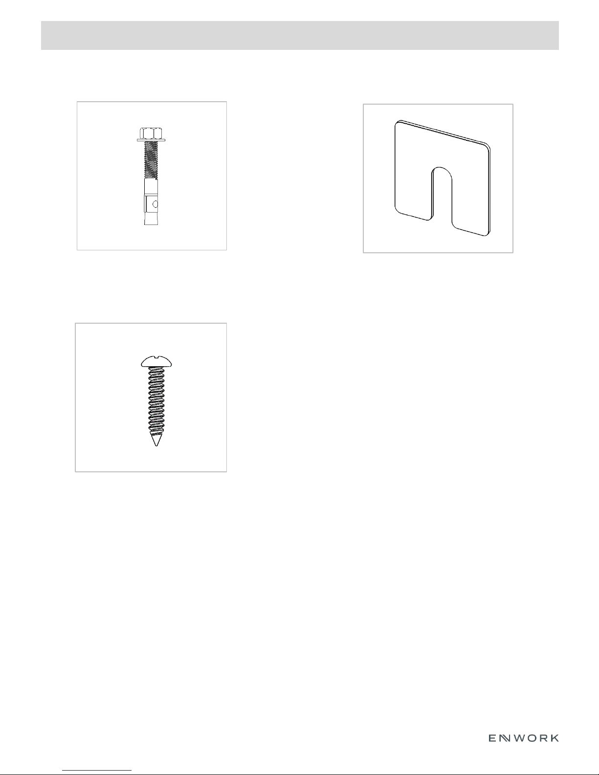
2) Parts and Fasteners Included
INSTALLATION GUIDE
½” x 3 ¾” Concrete Stud
Screw 1 (Black)
Aluminum Shim (Pack)
Page 5
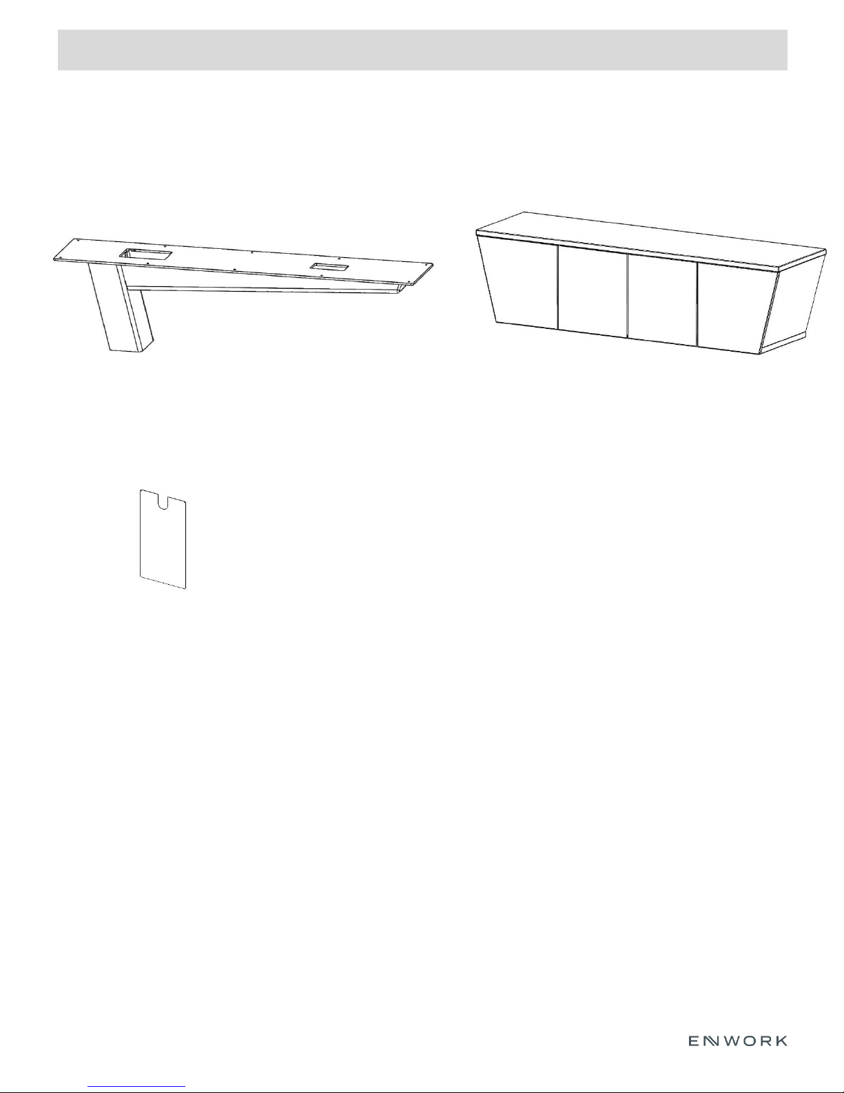
2) Parts and Fasteners Included
INSTALLATION GUIDE
Credenza Base
EQM-2242
Removable cover
EQM-1599
Tapered Credenza
EQL-2099-xxxx
Page 6
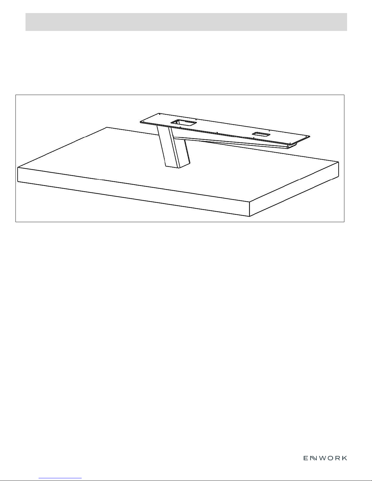
3) Assembly: Installing the Base
INSTALLATION GUIDE
Fig. 3
Page 7
3) Assembly:
INSTALLATION GUIDE
Fig. 3.1
Fig. 3.2
Fig. 3.3
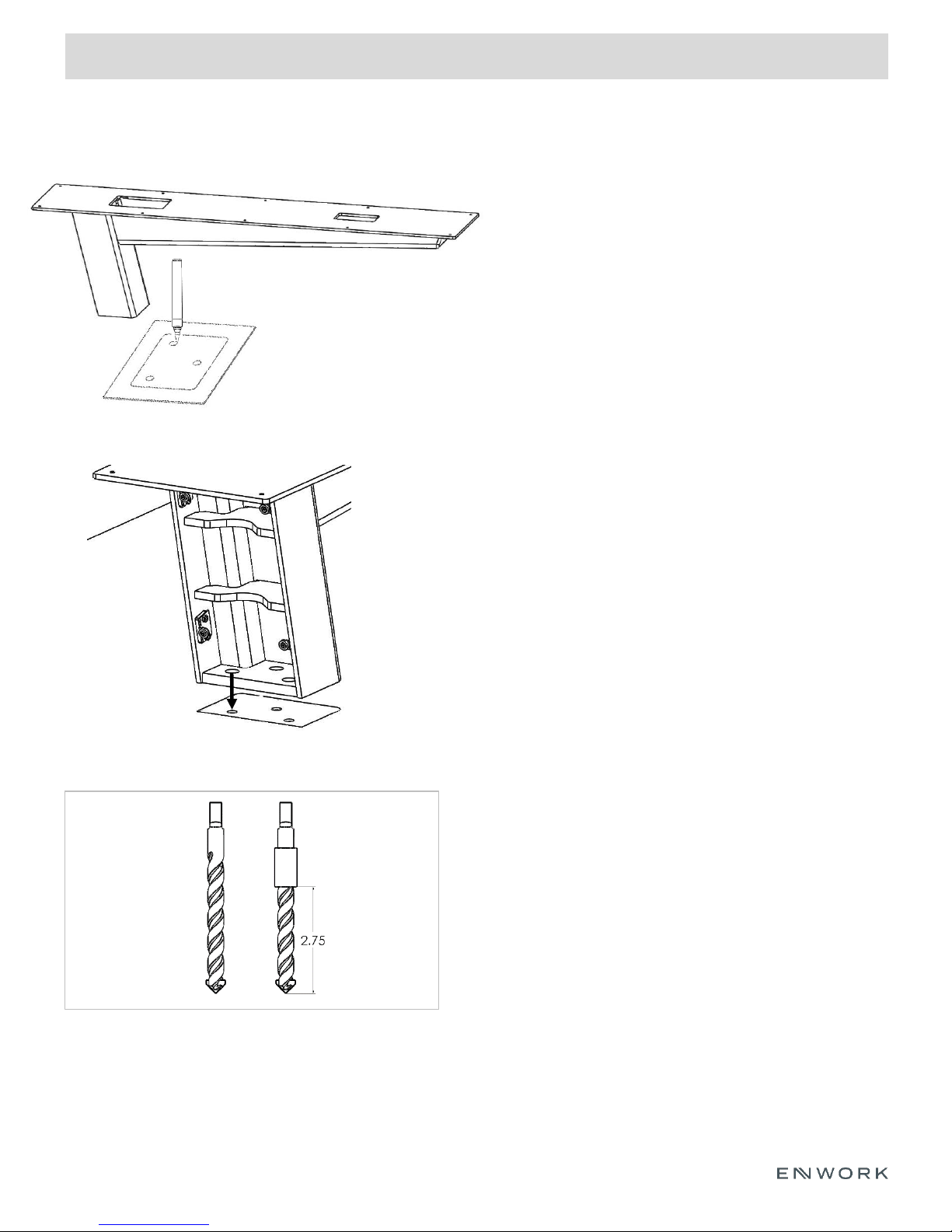
3.1.1) Locate final location of base
3.1.2) Using credenza base, trace hole location for base
placement and carpet removal
3.2.1) Set base over marked hole locations.
Note: Check that base is oriented as desired
3.2.2) Using a utility knife, cut away any carpet around
the base location
3.2.3) With carpet removed, double-check hole
locations and if not already there, mark hole locations.
Note: Hold the marker vertically and
spin the marker around the hole to get
the best result.
3.3.1) Measure 2 ¾” from the bottom of the ½”
diameter concrete drill bit and wrap drill bit with
tape creating a visual depth gauge.
Page 8
3) Assembly:
INSTALLATION GUIDE
Fig. 3.4
Fig. 3.5
Fig. 3.6
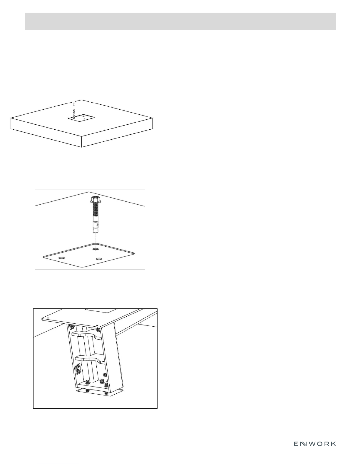
3.4.1) Drill marked hole locations to 2 ¾” deep.
3.4.2) Vacuum out the drilled holes to remove
dust that may prevent anchor from seating
properly.
3.5.1) Place one washer and one hex nut onto
provided concrete anchor so that the hex nut is
flush with the top of the anchor.
3.5.2) Insert anchor with washer and nut into the
the drilled floor hole. Using a hammer or
mallet pound anchors into drilled holes
until there is 1” - 1-1/2” protruding from
the floor.
3.5.3) Use ¾” socket or wrench to tighten anchor hex
nuts
3.5.4) Once all bolts has been tightened, loosen
and remove the washers and nuts.
3.6.1) Take the base and set into place, aligning
holes over bolts
3.6.2) With base now in place, use washer and hex
nut and tighten to base
Page 9
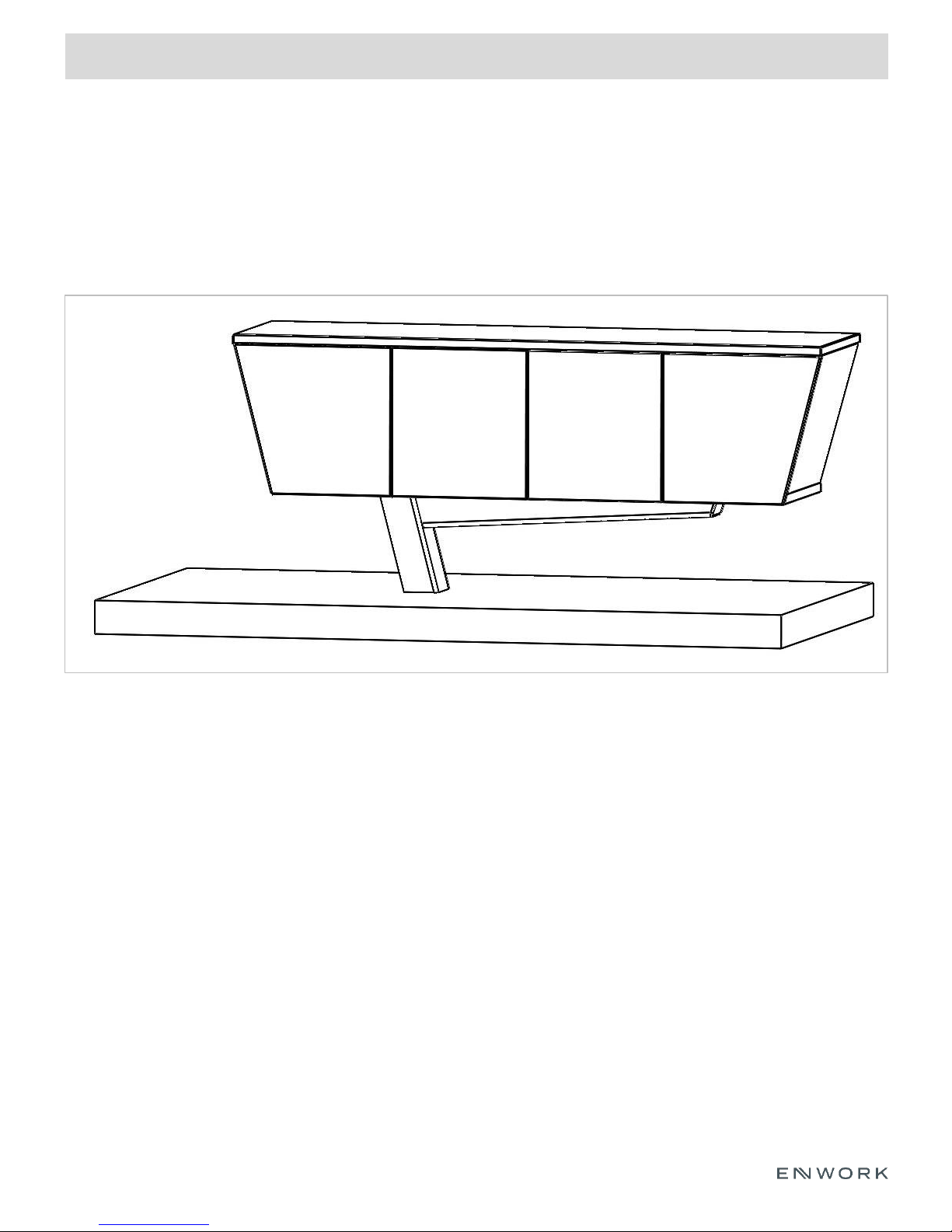
3) Assembly:
INSTALLATION GUIDE
Fig. 4
Page 10
3) Assembly:
INSTALLATION GUIDE
Fig. 4.1
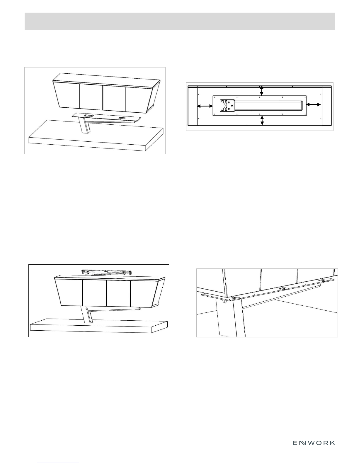
4.1.1) Place Credenza onto base
Installing Credenza continued
Fig. 4.2
4.2.1) Center credenza on the base, measuring
from the front, back, and sides of the credenza
to the top mounting plate of base.
w
w
x
x
4.3.1) Before securing credenza to base, ensure
that credenza is level.
Fig. 4.3 Fig. 4.4
4.4.1) Using aluminum shims, place between
top plate of base and bottom of credenza as
needed to level the credenza.
Note: If power routing is required, please
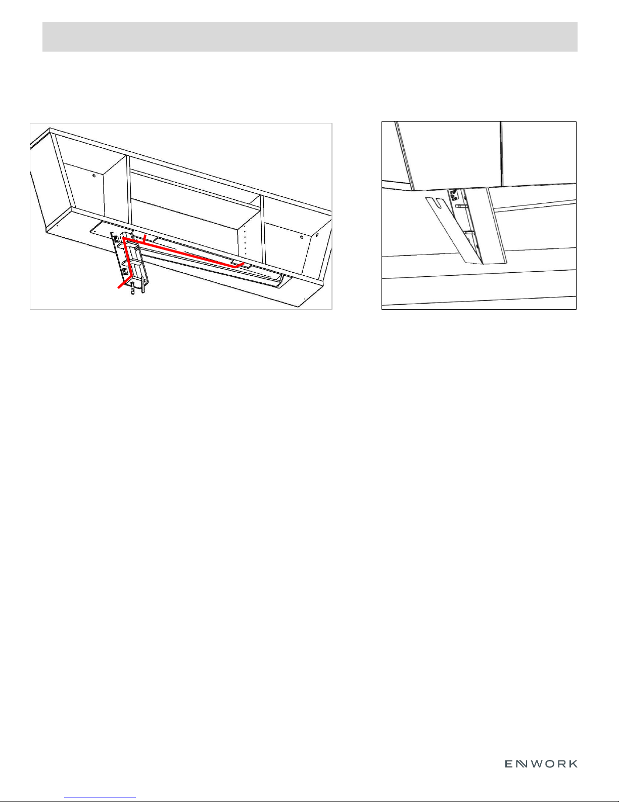
proceed to following steps for routing diagram.
4.4.2) Secure credenza to base using screw 1
Page 11
3) Assembly:
INSTALLATION GUIDE
Fig. 5.1
5.1.1) If power routing is needed, refer to
diagram above for routing through the base.
5.1.2) Once power cord is routed through base,
secure credenza to base using screw 1
Installing Credenza continued
5.2.1) Install the base cover by attaching it to
pre-installed magnets
5.2.2) Fig. 5.2 shows power routing hole up for
no power option
5.2.3) If power routing is needed, flip the cover
so that routing hole is down
Fig. 5.2
Page 12

12900 Christopher Drive Lowell, MI 49331
800.815.7251 www.enwork.com
Specifications subject to change without notice.
 Loading...