

Page 1
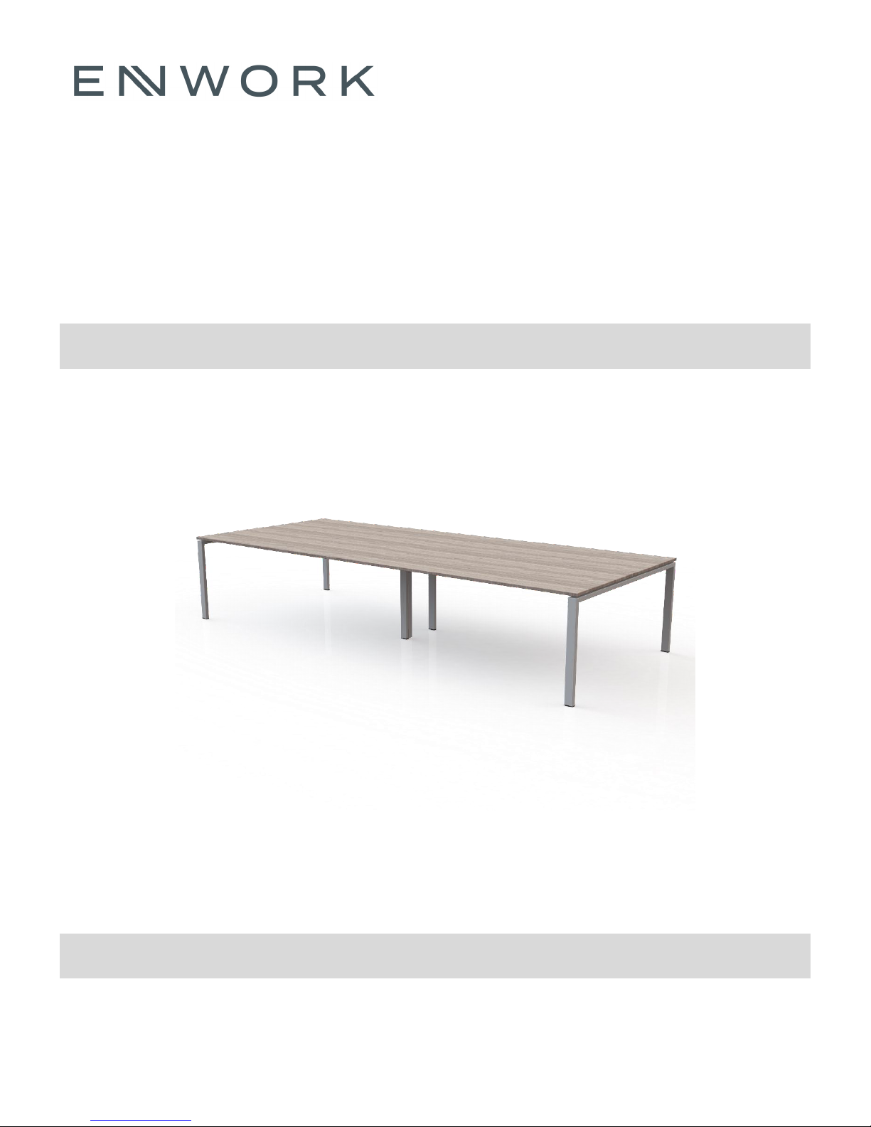
eBench Table
Conference Table
Revision A 02/01/17
Installation Instruction
Page 2
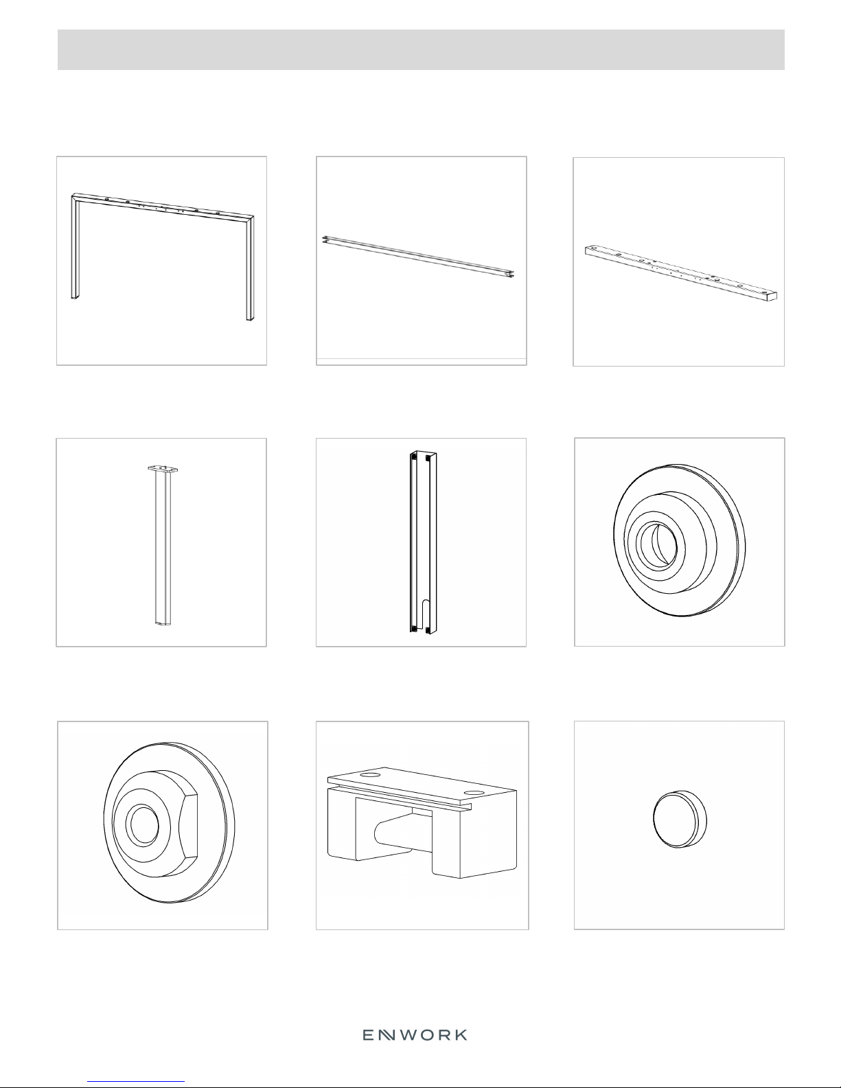
1) Parts and Fasteners Included
INSTALLATION GUIDE
EBE48 for 48”D tables
EBE60 for 60”D tables
End Base
EBSL
Mid Run Support Leg
EBCB48 / EBCB60 / EBCB72
Crossbar
EBM-1327
Power Infeed Cover
EBDD60
Connection Bar
EBF1
Washer Without Thread
EBF2
Washer With Thread
EBF3
Plastic Crossbar Connector
3
EBF9A
Plastic Glide
Page 3
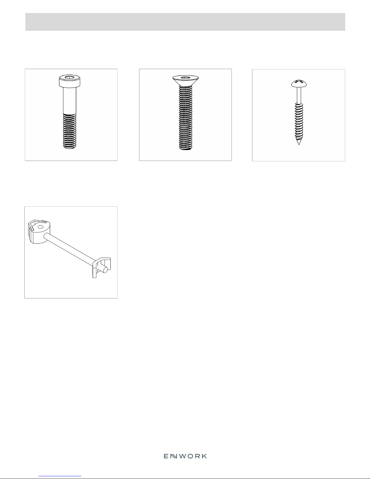
1) Parts and Fasteners Included
INSTALLATION GUIDE
200-28147
M8-1.25 x 40MM LOW HD
SOCKET CAP SCREW
200-28470
MINI ZIPBOLT CONNECTOR
200-26469
M8-1.25 x 45MM FLAT HEAD
SOCKET CAP SCREW
200-04314
10 x 1 ½” PAN HEAD
PHILLIPS
4
Page 4
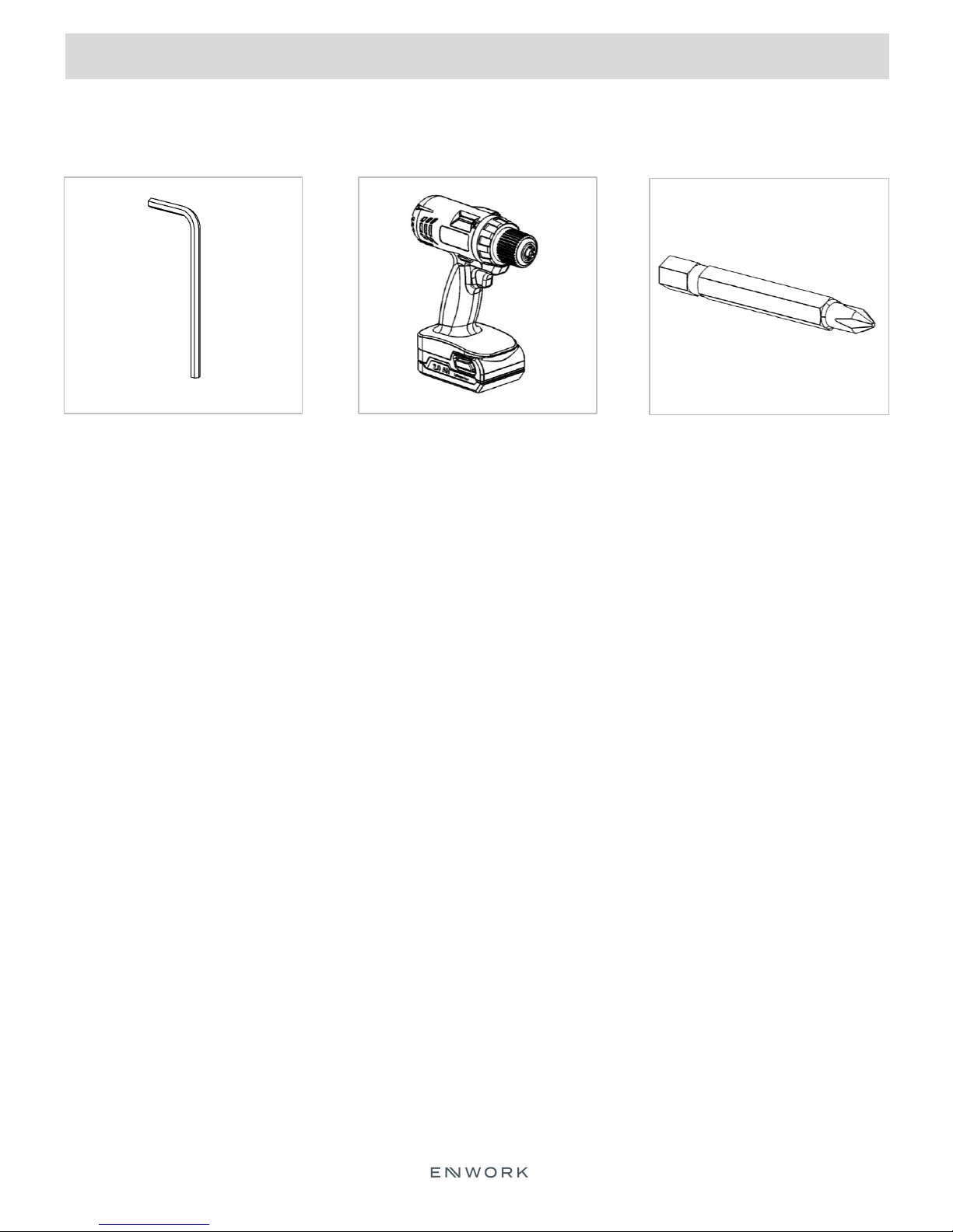
2) Tools and Supplies Required
INSTALLATION GUIDE
4MM & 5MM ALLEN
WRENCH
DRILL / DRIVER
#2 PHILLIPS DRIVER BIT
5
Page 5

3) Model Number Overview
INSTALLATION GUIDE
1 Bar eBench Table
EBZ4848 / EBZ4860 / EBZ4872
EBZ6048 / EBZ6060 / EBZ6072
2 Bar eBench Table
EBZ4896 / EBZ48120 / EBZ481442
EBZ6096 / EBZ60120 / EBZ601442
6
Page 6

INSTALLATION GUIDE
3) Model Number Overview
Cont.
3 Bar eBench Table
EBZ481443 / EBZ48156 / EBZ48168 / EBZ48180 / EBZ48192 / EBZ48204 / EBZ48216
EBZ601443 / EBZ60156 / EBZ60168 / EBZ60180 / EBZ60192 / EBZ60204 / EBZ60216
4 Bar eBench Table
EBZ482404
EBZ602404
7
Page 7

INSTALLATION GUIDE
3) Model Number Overview
Cont.
5 Bar eBench Table
EBZ482405
EBZ602405
Chart shows crossbar configuration for each length of table
8
Page 8

INSTALLATION GUIDE
3) Model Number Overview
Crossbars EBCBxx
EBCBxx Lengths
9
Page 9

4) Assembly:
INSTALLATION GUIDE
Fig. 1
- Attach EBF1 to all crossbar ends (EBCB48,
EBCB60, EBCB72)
Fig. 2 (for 2, 3, 4 and 5 bar tables only)
- Connect qty 2, EBDD60 to qty 2, EBSL using
fastener 200-26469, flat head screw.
- Note
- Holes on side of EBDD60 face outward.
- Countersunk holes on EBDD60 face up.
Fig. 3
- Connect crossbar to EBE48 or EBE60 using
qty. 1, EBF1, EFF2 and 200-28147
- Repeat for all crossbars.
- Note
- Connection to mid run leg shown in Fig. 2 is
the same as shown in Fig. 3.
Fig. 4
- Remove backer from disks on crossbar
(EBCB48 / EBCB60 / EBCB72) and attach
plastic disk (EBF9A) to adhesive.
- Place one EBF9A at all locations of stickers.
10
Page 10

4) Assembly
INSTALLATION GUIDE
Fig. 5
Attach surface using qty 2, 200-04314 screws through all EBF3 parts. Surface is centered all around base.
Leg cover EBM-1327 magnetically attaches to mid run legs for power / cord concealment.
Fig. 6
11
Page 11

12900 Christopher Drive Lowell, MI 49331
800.815.7251 www.enwork.com
Specifications subject to change without notice.
 Loading...