


I00224_JAN 2017
Call 1300 369 273
www.enware.com.au
Enware Australia Pty Limited
9 Endeavour Rd Caringbah NSW 2229 Australia
Ph: +61 2 8556 4000 Fax: +61 2 8556 4055

DIMENSIONS
(NOT TO SCALE)

COMPONENTS

TECHNICAL TABLE
Inlet Connection
15mm (1/2” BSP) male
Recommended Working Pressure Range
50 - 500 kPa *
Maximum Temperature
70°C *
Operating Voltage
24V AC
Power Consumption
Less than 9 W
Power Pack
Input: 230-240 V AC 50Hz
Output: 24 V AC 1.0 Amp
Cable Length: 1.8 metres
Sensor - Touch Activated
Programmable
Sensor Functions: On Time, Lockout (Off Time), Early
Stop, Periodic Cycle Flush 24 hrs
ON Time 3 sec – max 10 min,
OFF Time 6 sec – max 10 min.
(ON Time in increments of 3 sec)
Solenoid Valve
Brass
For use with potable water only.
COMPLIANCE
* Enware products are to be installed in accordance with the Plumbing Code of Australia and
AS/NZS3500.
Reference should also be made to the Australasian Health facility Guidelines (AHFG), ABCB and Local
Government regulations when considering the choice of, and the installation of these products.
NOTE: Enware Australia advises: 1. Due to ongoing Research and Development, specifications may
change without notice. 2. Component specifications may change on some export models.
This product must be installed and commissioned by a qualified plumber.

INSTALLATION - ROUGH IN
Determine Location of Shower
Wall depth: min 70mm – max 85mm from finished wall surface to the back of box.
This shower cannot be installed sideways, or upside down. The mixer body must be installed in the
correct direction, with the 2 inlets on the horizontal plane. This will ensure the handle points in the
correct orientation and to align with the “H” and “C” markings on the front panel.
In-Wall Body Component
1. Ensure plumbing lines are flushed prior to installation, as debris in cartridge will void
warranty.
2. Remove temperature adjustment lever handle and front panel from Shower Box, taking care
not to damage any cable while doing so. Disconnect spade connectors from solenoid if they
are connected.
3. Secure the Shower Box to the internal cavity within the wall. The Shower Box can be fixed to
a masonry wall or wall frame using screws suitable for the fixing method. (Fixing screws not
supplied.)
When mounting the Shower Box, take note of the minimum and maximum wall thickness
and the dimensions shown so that the nogging or recess is correctly positioned and takes
into account the thickness of the finished wall.
To increase the wall depth adjustability, unscrew the four Wall Depth Adjustment Nuts,
bring the position of Body Fixing Plate forward, and secure the Body Fixing Plate in place
again with four nuts located behind the plate.

4. Purge hot and cold water lines, and connect water supply pipework to the hot and cold
ISOLATION VALVE SPINDLE AT “ON” POSITION
WARNING:
Do not cut the wires or extend existing cables without
using the correct cable extension from Enware.
Cutting cables will void warranty.
inlets. Connect the shower outlet to the riser leading to shower rose / outlet.
NOTE: The mixer body has ‘H’ and ‘C’ markings to indicate the appropriate supply required
to each side of the mixer.
WARNING: Heat must not be applied to the inlets and outlet of the mixer as this will result
in damage to the O-rings and cartridge, and void warranty.
Check valves are supplied fitted at the inlets of the mixer. However this is does not qualify as
a backflow prevention device. Where required, the installer must install an appropriate
backflow prevention device before a shower hose according to the cross-connection hazard
rating.
5. Ensure the isolation valves are closed prior to turning on Hot and Cold Water supplies. The
Isolation Valve spindle has a slot which should be in a vertical position when closed. Use a
3mm Allen Key or flat head screw driver to turn the isolation valve.
6. Loosely place handle on spline of mixer cartridge.
7. Turn on Hot and Cold water supply and test for leaks within the pipework connection and
Isolation Valves. Open the Hot and Cold Isolation Valves by using a 3mm Allen key or flat
head screw driver and rotating the isolation spindles 90 degrees.
8. Run the cable for the power pack through a conduit, and have the connector inside shower
box. Power point has to be accessible to allow for possible future replacement, repair or
service.

9. Connect power cable to piezo button. Connect two spade connectors to the two side
connectors of the solenoid.

10. Turn on the power and test operation of the tap.
Note: Do not touch the piezo button for the first 10 seconds of turning the power on,
otherwise the button may enter into programming mode and re-program to a different
time setting.
If the piezo button needs to be re-programmed, refer to “Enware Electronic Piezo Button
Program” in the following section.
Turn mixer handle and test functionality of the shower system. If there is any problem see
Troubleshooting Section following or contact Enware.
11. Disconnect piezo button from power supply and solenoid. Close both the Hot and Cold
isolation valves to turn off both water supplies, and keep the front panel removed until
finishing trades are complete.
INSTALLATION - FIT OFF (FACIA AND HANDLE)
12. Once finished wall is complete, connect power cable to piezo cable and connect piezo to
solenoid.
Note: Do not touch the piezo button for the first 10 seconds of turning the power on,
otherwise the button may enter into programming mode and re-program to a different
time setting.
13. Turn on hot and cold water. Operate the mixer and solenoid to ensure system is still
functional.
14. Seal any gaps between the wall cut-out and the shower box, with appropriate silicone
sealant.
15. Use foam seal supplied to seal between the wall surface and the back of the front plate.
Run a thin bead of silicone sealant along the back top edge of the front plate.
Place the Front Plate over the mixer and push firmly against the wall. Secure using the 6
Allen key fixing screws provided.
Wipe off and clean any excess silicone sealant.
16. Screw on Flange over the mixer, and slide the chrome sleeve on.
17. Place handle onto the cartridge spline. Fit the handle fixing screw and tighten to secure the
handle.
18. Test the operation of tap, check that the temperature settings and the orientation of mixer
handle align, and adjust the position of handle if required.
OPERATING THE MIXER
Press the electronic piezo button once to turn on water flow. Water fill flow for the set time
duration.
To adjust temperature, rotate the temperature adjustment lever towards H to make it
hotter, or C for cold.
Press the electronic piezo button once to turn off water flow. (This function is only available
if STOP function is set on the electronic piezo button program.)
If any Lockout Time (or OFF Time) is set, mixer cannot be turned on for the set period of
time once it is turned off.

TROUBLESHOOTING
PROBLEM
CAUSE
RECTIFICATION
Tap/ Water continues to
flow
Debris in solenoid valve
Take solenoid apart and clean debris from
plunger or diaphragm
Piezo button has ben reprogrammed to a
different setting
Re-program piezo button. *
Solenoid diaphragm is
damaged
Replace solenoid diaphragm (service kit
ENMS229)**
Piezo button re-programs
itself to a different setting
Power supply has been
turned off and back on
again, and user has
touched the piezo
Re-program piezo button.*
Check power supply, ensure there is a
stable, continuous power source.
Tap does not activate
Power turned off
Turn power on.
Power pack damaged
Replace power pack.
Check power supply, protect the power
pack from electrical surge.
Solenoid 1/2" (includes 2x 1/2" nipples)
EMS804
Transformer
EMDS800
Extension Lead for Transformer (2m)
EMDS801
Extension Lead for Solenoid (Molex Connectors)
EMFS313 (4m)
EMFS314 (2m)
Solenoid service kit (1/2” AC)
ENMS229
Electronic Touch Piezo Button (Programmable)
EMS811
(Default 6 sec ON, specify required time when
ordering)
* For electronic piezo button program instructions, refer to “Enware Electronic Piezo Button Program” in the following
section.
** For Solenoid Servicing instructions, refer to separate document “Enware EMS804 24V Solenoid Service & Maintenance
Instructions_I00228”.
SPARE PARTS
CLEANING
Enware Product should be cleaned with a soft damp cloth using only mild liquid detergent or soap
and water. Do not use cleaning agents containing a corrosive acid, scouring agent or solvent
chemicals. Do not use cream cleaners, as they are abrasive. Epoxy coated surfaces should only be
cleaned with a cloth and clear water or mild detergent. Use of unsuitable cleaning agents may
damage the surface. Any damage caused in this way will not be covered by warranty.
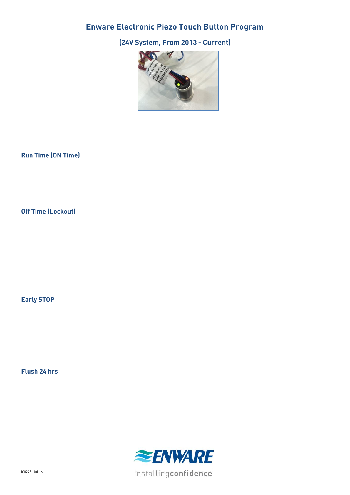
Enware Programmable Piezo Button is a touch-activated electronic switch that can be easily set to a desired timing.
Its versatility allows it to be set again to a different program on site should there be any change of mind.
The electronic button timing program offers the following features:
The length of time you want the valve to turn on.
Minimum length 3 seconds, maximum length 10 minutes.
In increments of 3 seconds. (3, 6, 9, 12 .... etc)
Factory default time is 6 seconds.
The length of time you want the valve to stay off once stopped.
Minimum length 0 seconds, maximum length 10 minutes Off Time.
In increments of 3 seconds (3, 6, 9, 12 .... etc)
Choose “0” (zero) if you do not want any Lockout time. (i.e. allow consecutive use.)
This function prohibits the user from turning on the valve again for the set period of time - that is, the valve
is “locked out” once turned off. It is useful when you want to limit the length of a shower to a set time and
prevent consecutive use, excessive use or water wastage. The Lockout time becomes effective every time
the switch turns off.
Once turned on, this function allows the user to stop the flow of water even if the set Run Time has not
finished yet. For example, a shower is set to run for 3 minutes but user decides to turn it off at 1 minute.
(Note that any lockout time still applies once it is turned off.)
Choose “Yes” if you want this function.
Choose “No” if you want the water to flow for the set Run Time without interruption.
Default factory setting is “No” (without Stop).
Automatically activates the valve every 24 hrs and runs for the set Run Time, particularly useful for
Legionella control and reducing the risk of bacteria growth in the water supply line.
Choose “Yes” if you want the valve to automatically turn on every 24 hrs.
Choose “No” if you do not want this function.
Default factory setting is “No” (without 24 hr flush).

1. To set the button to a new program, firstly turn the power OFF to the button. This can be done by either
Step 1
Step 2
Step 3
Select Software Configuration
Red LED is ON
Green LED is ON
Red LED is ON
No. of
Presses
Stop
Flush 24h
On
Time(Sec)
Increment
Step (Sec)
Off Time
(Sec)
Increment
Step (Sec)
1
No
No
3--30
3
0-60 6 2
Yes
No
3--30
3
0-60
6
3
No
Yes
3--30
3
0-60 6 4
Yes
Yes
3--30
3
0-60 6 5
No
No
30-300
30
0-60 6 6
Yes
No
30-300
30
0-60 6 7
No
Yes
30-300
30
0-60
6
8
Yes
Yes
30-300
30
0-60 6 9
No
No
60-600
60
0-600
60
10
Yes
No
60-600
60
0-600
60
11
No
Yes
60-600
60
0-600
60
12
Yes
Yes
60-600
60
0-600
60
13
Yes
No 6 -- 0 --
turning the power OFF at the power point, or disconnecting the power connection close to the button.
2. You will need to be able to see the two LED’s – green and red – located at the back of the piezo button, so
the front facia panel may need to be taken off the wall to access it.
3. Connect or turn ON the power to the switch. As soon as the power is on, a 3-second programming window
opens. If the switch is not pressed in this time frame, both RED and GREEN LED’s flash alternately, and the
switch returns to the last program it was set to.
4. Press the switch ONCE within the 3-second programming window. Red LED turns on.
5. Without delay, press the switch to select the program number. Press the switch slowly but firmly at 1-second
intervals. (e.g. 4 presses to select program 4). The green LED blinks every time the switch is pressed. Valid
programs are 1 to 12. Pressing the switch 13 times returns the switch to factory settings as per table.
6. Once the program No. has been selected, the RED LED will turn off and the GREEN LED will turn on. The
switch is now ready to set the “ON time”. Each press of the switch will increase the “ON time” by the
indicated increments. e.g. If program no.4 has been selected the increments are by 3 seconds each (one
press-3 sec; 2 presses-6 sec and so on), therefore pressing the switch 4 times will set the “ON time” to 12
seconds. The RED LED blinks for each press of the switch.
7. Now the “ON time” has been selected, the GREEN LED will turn off and the RED LED will turn on. The switch
is now ready to set the “OFF time”. Each press of the switch will cause the GREEN LED to blink, increasing the
“OFF time” by the increments indicated on table. e.g. If program no.4 has been selected the increments are
by 6 sec, starting at 0 sec. (one press – 0 sec; 2 presses – 6 sec and so on for program 4. Button has to be
pressed at least once.) Refer to table.
8. Once the “OFF time” is set, the GREEN and RED LED’s will blink alternately indicating that the switch is
exiting the program mode.
9. Switch is now set.
PROGRAMMING TABLE

WARRANTY
Product Warranties for Australia
Effective 1 September 2014
Enware Australia Pty Limited (ACN 003 988 314) (“we” or “us”) warrants that this product (also
referred to as “our goods”) will be free from all defects in materials and workmanship for 12
months* from the date of purchase. Our liability under this warranty is limited at our option to the
repair or replacement of the defective product or part, the cost of repair of the defective product or
part or the supply of an equivalent product or part, in each case if we are satisfied the loss or
damage was due to a defect in the materials or workmanship of the product or part. All products
must be installed in accordance with the manufacturer’s instructions, the PCA, and AS/NZS3500
including any other applicable regulatory requirements.
Making a claim
To make a claim under this warranty you must notify us in writing within 7 days of any alleged defect
in the product coming to your attention and provide us with proof of your purchase of the product
together with a completed Product ServiceRequest form (ENF091), which is available on request
from our office or website (see contact details below). All notifications and accompanying forms
must be sent to us marked for the attention of the Enware Australia Pty Limited, 9 Endeavour Road,
Caringbah NSW 2229. We can also be contacted by telephone (1300 369 273) or by email
(info@enware.com.au). Your costs in making a claim under this warranty, including all freight,
collection and delivery costs, are to be borne and paid by you. We also reserve the right at our cost
to inspect any alleged defect in the product wherever it is located or installed or on our premises.
Exceptions
This warranty does not apply in respect of any damage or loss due to or arising from:
a) Failure by you or any other person to follow any instructions for use (including instructions and
directions relating to the handling, storage, installation, fitting, connection, adjustment or repair of
the product) published or provided by us;
b) Failure by you or any other person responsible for the fitting, installation or other work on the
product to follow or conform to applicable laws, standards and codes (including the AS/NZ 3500 set
of Standards, all applicable State and Territory Plumbing Codes, the Plumbing Code of Australia and
directions and requirements of local and other statutory authorities); or
c) Any act or circumstance beyond our control including faulty installation or connection, accident,
abnormal use, acts of God, damage to buildings, other structures and infrastructure and loss or
damage during transit or transportation of the product.
Other conditions
Except as provided or referred to in this document, we accept no other or further liability for any
damages or loss (including indirect, consequential or economic loss) and whether arising in contract,
tort or otherwise. Any benefits available to you under this warranty are in addition to any nonexcludable rights or remedies you may have under applicable legislation, including as a “consumer”
under the Australian Consumer Law. To that extent you need to be aware that: Our goods come with
guarantees that cannot be excluded under the Australian Consumer Law. You are entitled to a
replacement or refund for a major failure and for compensation for any other reasonably foreseeable
loss or damage. You are also entitled to have the goods repaired or replaced if the goods fail to be of
acceptable quality and the failure does not amount to a major failure.
*12 Months parts and labour warranty on the complete assembly - Electronic Tapware.
 Loading...