

Page 1
Installation Instructions
FOR USE IN AUSTRALIA
Call 1300 369 273
www.enware.com.au
Enware Australia Pty Limited
9 Endeavour Rd Caringbah NSW 2229 Australia
Ph: +61 2 8556 4000 Fax: +61 2 8556 4055
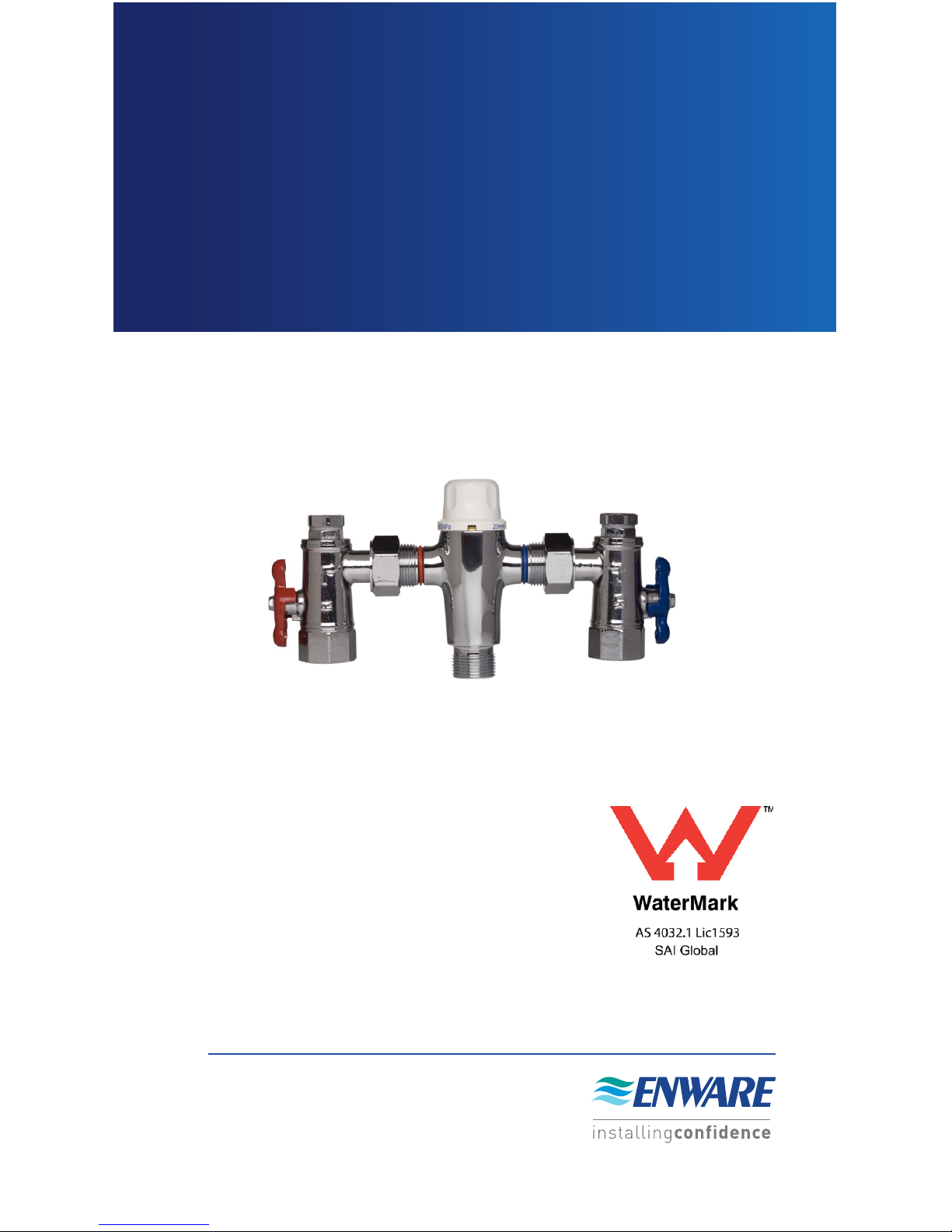
AQUABLEND 2000
THERMOSTATIC
MIXING VALVE
I00109_Jul 16 IS226
Page 2

www.enware.com.au Call 1300 369 273 2
PRODUCT FEATURES
Complies with the
requirements of AS4032.1
-Thermostatic Mixing
Valves
Provides high stability of
mixed water temperature
even under changing inlet
conditions
Ensures rapid shut down
of mixed outlet ow in the
event of hot or cold water
supply failure
Designed for quick and
simple in-situ servicing
Suitable for installation into
AS3500 compliant systems
with hot water temperature
as low as 55°C for
temperature differential
Fitted with a Tamper
Resistant temperature
adjustment mechanism
installingcondence
Enware reserves the right to change any product specification or information
contained in this publication, at any time and without notice. Every care
has been taken to ensure accuracy in the Preparation of this publication
which has been issued for guidance only. No liability can be accepted for any
consequences which may arise as a result of its application. Enware = trade
mark of Enware Australia Pty Limited.
Aquablend TMV’s are exclusively manufactured for Enware Australia Pty Limited
by Reliance Worldwide, 27-28 Chapman Place, Eagle Farm, Qld, 4009 Australia.
The ENWARE AQUABLEND 2000
Thermostatic Mixing Valve is a
high performance Thermostatic
Mixing Valve suitable for a wide
range of applications. The valve
is designed to comply with
AS4032.1 - Thermostatic Mixing
Valves.
AQUABLEND 2000 THERMOSTATIC MIXING VALVE
CONTENTS
SAFETY page 3
PRODUCT DESCRIPTION page 4
RECOMMENDED PRESSURES
AND TEMPERATURES
page 7
FLOW SIZING GRAPH page 8
INSTALLATION page 9
COMMISSIONING OF THE VALVE page 12
MAINTENANCE & SERVICING page 15
TROUBLE SHOOTING page 17
SPARE PARTS page 19
COMMISSIONING REPORT page 20
SERVICING REPORT page 23
WARRANTY page 26
Page 3

3 Call 1300 369 273 www.enware.com.au
SAFETY
The ENWARE AQUABLEND 2000 Thermostatic Mixing Valve
is a high performance valve designed to give stable and
dependable operation, provided it is installed, commissioned,
operated and maintained as per the recommendations
outlined in this manual. It should be noted however that this
valve should not be considered as an alternative to adequate
supervision and duty of care during its use and operation.
Note: When installed, the mixing valve, inlet controls,
pipework and the surrounding area may become hot, which
may cause burn injuries. Precautions should be taken to
ensure that these surfaces cannot cause such injuries.
Page 4
www.enware.com.au Call 1300 369 273 4
PRODUCT DESCRIPTION
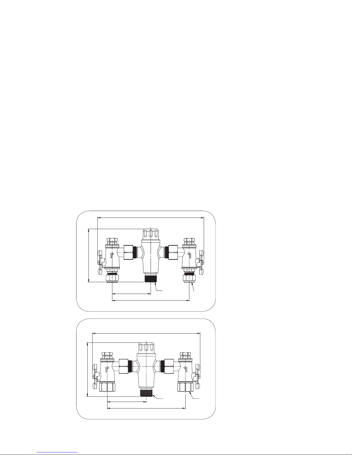
The ENWARE AQUALBLEND 2000 Thermostatic Mixing
Valve is available in two variations, complete with inlet service
ttings. The inlet to the ttings is ½” BSP male for ATM711,
and ¾” BSP female for ATM713. The outlet from both valves
is ¾” BSP male. The service ttings consist of isolating ball
valves, strainers, pressure test points and non-return valves.
The strainers can be serviced and cleaned without disturbing
the installation (refer to Maintenance & Servicing Pg 15).
The inlet service ttings also incorporate union type ttings
enabling the thermostatic mixing valve to be removed from its
installation without disturbing its pipework.
The schematics and dimensions of the Aquablend 2000 Male
& Female valves and corresponding order codes are shown
below in Figure 1 and Figure 2 respectively.
3/4" BSP
3/4" BSP
88
118
176
246
Figure 2
1/2" BSP
3/4" BSP
118
176
88
244
Figure 1
Figure 1 Physical Size
AQUABLEND 2000 –
Polished, chrome
plated nish on the
body & inlet ttings.
½“ BSP Male Inlet
ttings with compression nuts. ¾” BSP
Male Outlet Fitting.
Dry Weight 1.7kg
ORDER CODE
ATM711
Figure 2 Physical Size
AQUABLEND 2000 –
Polished, chrome
plated nish on the
body & inlet ttings.
¾” BSP Female
Inlet ttings. ¾” BSP
Male Outlet Fitting.
Dry Weight 1.7kg
ORDER CODE
ATM713
Page 5
5 Call 1300 369 273 www.enware.com.au
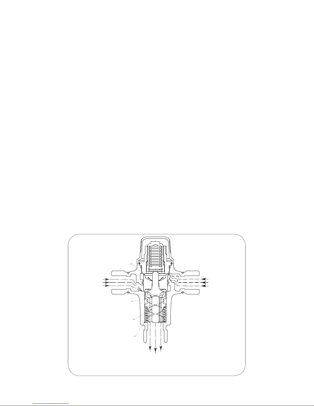
Figure 3 (below) shows a general arrangement drawing of
the ENWARE AQUABLEND 2000 Thermostatic Mixing Valve
showing the method of operation.
Hot and cold water is supplied to each side of the valve
respectively. The hot water enters through a port below the
Piston, the cold water enters above the Piston. Upon entry
the water begins to blend and enters the Mixing Tube. At
this point the mixed water contacts the thermostatic wax
Element. The Element will extend or contract to match the
water temperature it is exposed to causing the Piston to move,
thereby regulating the amounts of hot and cold water entering
the valve. This thermostatic mechanism maintains the mixed
water temperature at a constant temperature.
If for example the inlet hot pressure dropped, the ow of hot
water into the valve would be reduced and the valve would
react as per the following sequence of events:
• Element is exposed to mixed water at a reduced temperature
• Thermostatic Element contracting
• Piston is pushed upwards by the return spring restricting cold
HOT
INLET
COLD
INLET
MIXED
OUTLET
RETURN
SPRING
THERMOSTATIC
ELEMENT
MIXING
TUBE
PISTON
Figure 3 - General Arrangement Drawing
Page 6

www.enware.com.au Call 1300 369 273 6
ow, consequently opening more of hot port
• Valve attempts to restore itself to original temperature setting
Similarly if the hot inlet temperature dropped, the element
would again see blended water at a lower temperature and
therefore the Element would again contract reducing the
cold port piston gap and hence supply more hot water and
less cold. Once again the valve attempts to restore itself to
its original setting. This will occur for all changing conditions
including changes to ow rate, inlet temperatures and inlet
pressures.
In the event of a sudden loss of the cold water supply the
Piston will shut off the hot port thus stopping any ow through
the valve. The valve will also shut down the cold supply if there
is a hot water failure.
Page 7

7 Call 1300 369 273 www.enware.com.au
RECOMMENDED PRESSURES
& TEMPERATURES
MIXED OUTLET TEMPERATURE
Temperature Adjustment Range 38-50°C
INLET TEMPERATURES
Cold Supply
Minimum
5°C
Maximum
30°C
Hot Supply
Minimum
55°C
Maximum
90°C
Hot to Mix Temperatures Differential for
Stable Operation
Minimum
10°C
Cold to Mix Temperatures Differential
for Stable Operation
Minimum
5°C
FLOW RATES - TO ENSURE STABLE CONDITIONS
Minimum
2 lpm (4 lpm recommended for optimum
performance)
Maximum
38 litres/min @ 300kPA Pressure loss as per ow
sizing graph
DYNAMIC INLET PRESSURES
Hot & Cold Inlet Pressures
Minimum 20kPa
Maximum 500kPa
STATIC INLET PRESSURES
Hot & Cold Inlet Pressures Maximum 1600kPa
INLET PRESSURE RATIO
H - PL = H¹
C - PL = C¹
H¹ : C¹ = Max 10:1
C¹ : H¹ = Max 10:1
H = Hot inlet pressure
C = Cold inlet pressure
PL = Pressure Loss
Refer to page 25 - Appendix 1 for more information
* 4 litres/minute is recommended as the optimum minimum ow rate.
** For optimum operation it is recommended that the hot & cold water supply
pressures be balanced to within +/- 10%.
NOTE: Notwithstanding the above, compliance with AS3500 must
be maintained.
Page 8

www.enware.com.au Call 1300 369 273 8
0
50
100
150
200
250
300
350
Flow Rate (L/min)
Pressure Loss (kPa)
HEADLOSS CHARACTERISTICS OF AQUABLEND 2000
0510 15 20 25 30 35 40
NOTE: Stable temperature water is available at 2 litres/
minute however to ensure optimum performance it is
recommended the minimum outlet ow of the mixing valve
during operation should be 4 litres/minute.
It is important that the valve is sized such that the ow rates
from the outlets are not less than those listed in AS3500.1
Sec 3. The pipework between the valve and the system must
be sized in accordance with AS3500.1 to ensure the water
velocity in the pipework is within the allowed limit.
If the valve is to be installed and operated under unequal
inlet pressures the lower inlet pressure determines the outlet
ow rate. However, for optimum performance and stability
it is recommended that the valve be installed with balanced
dynamic inlet pressures (+/- 10%).
FLOW SIZING GRAPH
The ENWARE AQUABLEND 2000 Thermostatic Mixing Valve
is suitable for many applications. The Headloss Characteristic
for Mixed Outlet Flowrate versus Balanced Inlet Pressure is
shown below in Figure 4. It is important that the valve is not
oversized for its intended application.
Figure 4
Page 9

9 Call 1300 369 273 www.enware.com.au
INSTALLATION
The ENWARE AQUABLEND 2000 Thermostatic Mixing Valve
should be installed using the appropriate Standard, Code of
Practice and Legislation applicable to each state and following
the details outlined in this section.
The ENWARE AQUABLEND 2000 must be installed by a
licensed plumber, or where applicable, a licensed plumber who
has undertaken T.A.F.E. or equivalent accredited training in
Thermostatic Mixing Valves.
NOTE: To effectively control microbial hazards during
system design, installation, commissioning and
maintenance, the requirements outlined in AS/NZS3666 and
local legislation shall be adhered to.
Inlet connections on the valve are clearly marked. The hot
inlet is indicated by a red identication ring on the inlet
and the cold inlet by a blue identication ring.
If the valve is not installed correctly then it will not function
correctly and may put the user in danger. It may also void the
warranty of the valve.
Prior to the installation of the valve, the system must be
checked to ensure that the system operating conditions fall
within the recommended operating range of the AQUABLEND
2000 Thermostatic Mixing Valve as detailed on page 7. If
the hot water supply temperature is greater than 90°C
the valve may be damaged. A suitable temperature limiting
valve must be tted to the hot water supply, prior to the inlet
ttings, if the temperature of the hot water will rise above 90°C.
This temperature limiting valve must be installed as per the
manufacturer’s instructions. Alternatively, use AQUABLEND
1500 SOLAR - Code ATM715. It is also important that
both of the inlet dynamic supply pressures are 500kPa
or less. If either supply pressure exceeds 500kPa then a
suitable pressure reducing valve must be tted prior to the
inlet control valve to reduce the pressure to an acceptable
limit. These pressure reducing valves must be installed as per
the manufacturer’s instructions. In order to achieve optimum
Page 10

www.enware.com.au Call 1300 369 273 10
performance from the valve it is recommended that the inlet
pressures are balanced to within 10% of each other. The water
quality conditions should be checked to ensure they do not
exceed the limits as listed in Section 1.6 of AS3500.4. If they do
exceed these limits then it will be necessary to install a water
softener or water treatment device.
NOTE: In some installations where certain types of
tapware, such as ick mixers and solenoid valves, are
used; the water pressure may be seen to spike outside that
recommended for the valve during rapid shut off conditions
with these types of devices. Even if the spike only lasts a
split second it is still considered to be outside the operating
conditions and may cause the valve to operate incorrectly.
In the event that this does occur measures must be taken
to control the spike, such as inline pressure reducing valves
directly before the valve inlets.
To ensure that the mixing valve operates correctly it is
necessary that the pipework is thoroughly ushed with
clean water before the valve is installed. This will remove
any physical contaminants from the pipework, ensuring
trouble-free operation. During the ushing procedure care
should be taken to prevent water damage occurring to the
surrounding area.
It is required by AS3500.4 Sec 3 that “Each Thermostatic
Mixing Valve shall have an isolating stop tap/valve, line
strainer and non-return valve tted to the hot and cold water
supply lines”. The inlet ttings supplied with each TMV will
ensure this requirement is met. If the ENWARE AQUABLEND
2000 Thermostatic Mixing Valve is to be installed without the
supplied inlet control valves then it will be necessary to install
a separate isolating valve, non-return valve and strainer to
both inlets to the valve. Strainers must be tted to prevent
any particulate contamination from entering the valve. These
strainers should be 60 Mesh stainless steel. Isolating valves
are required so that the water supply to the valve can be
Page 11
11 Call 1300 369 273 www.enware.com.au
isolated in the event that servicing is required. Non-return
devices must also be tted to both the hot and cold inlets to
prevent cross-connection.
The valve should be installed so it can be accessed easily
for maintenance or servicing. The valve can be installed in a
wall cavity, under a basin or on a wall, however it is essential
that the mixing valve and inlet ttings are easily accessible for
servicing.
During installation or servicing heat must not
be applied near the mixing valve or inlet ttings,
as this will damage the valve and inlet tting
internals. Failure to comply with this requirement will
damage the valve and ttings. It will put the user at risk,
and it will void the warranty of the valve.
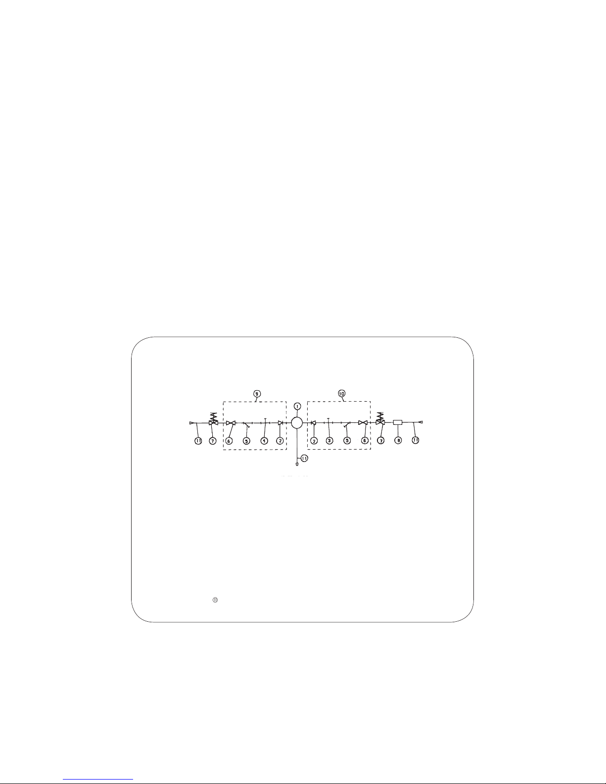
SCHEMATIC INSTALLATION DIAGRAM
THERMOSTATIC MIXING VALV E
NON RETURN VALV E
HOT WATER TEST POINT
COLD WATER TEST POINT
LINE STRAINER (60 MESH STAINLESS STEEL)
ISOLATING VALVE
PRESSURE LIMITING VALVE (IF REQUIRED)
TEMPERATURE LIMITING VA LVE (IF REQUIRED)
COLD WATER INLET CONTROL VALVE
HOT WATER INLET CONTROL VALVE
PIPEWORK
COLD SUPPLY
HOT SUPPL
Y
MIXED OUTLET
Figure 5 - Schematic Installation Diagram
Page 12

www.enware.com.au Call 1300 369 273 12
COMMISSIONING OF THE VALVE
Upon completion of the installation, the valve should be
tested & commissioned as per the procedure outlined below
or as specied by the local authority. The entire procedure
should be read through thoroughly prior to the commissioning
of the valve. A calibrated digital thermometer having rapid
response time with maximum temperature hold, small at
bladed screwdriver and the adjusting key (supplied with the
AQUABLEND 2000) will be required to check & set the outlet
mixed temperature of the valve. Enware provides a complete
test kit for this procedure.
(Order Code ATMS1200)
• Ensure all outlets that will be serviced by the valve have
adequate warning signs posted to ensure that no outlet is used
during commissioning
• Open the cold supply line to the valve, then open the hot
supply line, ensuring there are no leaks
• Open the outlet that is serviced by the shortest length of pipe
work between the mixing valve and outlet xture
• Allow the mixed outlet to ow for at least 60 seconds to
allow the temperature to stabilise before taking a temperature
reading at the outlet with a digital thermometer. For optimum
performance the ow rate should be at least 4 litres/min.
The ow rate can be checked with the aid of a known size
container and a stopwatch or an Enware Flowcup supplied
with ATMS1200. The temperature should be taken at the
closest outlet served by the thermostatic mixing valve
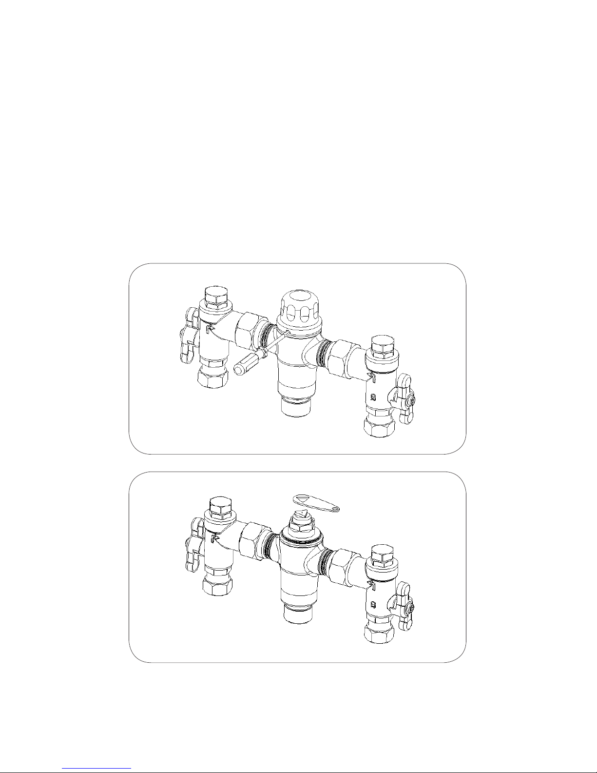
If the outlet temperature requires adjustment the following
steps are required:
TEMPERATURE ADJUSTMENT
1. Using a small at bladed screw driver lever the protective
cover off the valve (Figure 6). (over page)
2. Fit the supplied key over the adjusting spindle (Figure 7)
• To increase the mixed outlet temperature, rotate the
spindle anti-clockwise
• To decrease the mixed outlet temperature, rotate the
spindle clockwise
3. Allow the mixed outlet temperature to stabilize for 60
Page 13
13 Call 1300 369 273 www.enware.com.au
seconds and once again take a temperature reading.
Repeat the procedure until the desired temperature has
been reached.
4. Push the top cover rmly on to the top of the valve until it
‘snaps’ back into place.
5. Check that the outlet temperature is stable over the full
range of ow rates and that the ow rate is adequate for the
application.
6. Close the outlet.
7. The mixing valve is now set and locked.
Figure 6
Figure 7
Ensure that the test plugs in the top of the inlet ttings are tight
Page 14

www.enware.com.au Call 1300 369 273 14
SHUT DOWN TEST
Now that the mixing valve has been set and locked it is
necessary to perform a shut down check.
• Allow the mixed water temperature to stabilise and note the
outlet temperature. While holding a digital thermometer in the
outlet ow, quickly isolate the cold water supply to the valve.
The outlet ow should quickly cease owing. As a guide the
ow should be less than 0.2 litre/min following the isolation.
Monitor the maximum outlet ow temperature, record this on
the Commissioning Report (page 20). The temperature should
not exceed that allowed by the applicable standard or code of
practice for each state. Restore the cold water supply to the
valve. After the mixed water temperature has stabilised note
the outlet temperature ensuring the outlet temperature has reestablished.
• Repeat the above test, except this time quickly isolate the
hot water supply to the valve. The outlet ow should quickly
slow to a trickle - as a guide typically less than 0.4 litre/
min@500kPa down to less than 0.2litre/min@100kPa following
the isolation. Restore the hot water supply to the valve and
measure and record in the Commissioning Report (page 20)
the outlet temperature after the mixed water temperature has
stabilised ensuring the outlet temperature has re-established.
• Ensure that all details of the Commissioning Report are
completed & signed by the relevant signatories & a copy is
kept with the installer and owner of the premises.
The valve is now commissioned and it can be used within the
technical limits of operation.
Page 15
15 Call 1300 369 273 www.enware.com.au
MAINTENANCE AND SERVICING
The ENWARE AQUABLEND 2000 Thermostatic Mixing Valve
will only require minimal preventative maintenance work to
ensure it operates at its optimum level of performance. The
valve should be commissioned, and serviced in accordance
with AS4032.3 and the manufacturing specications.
ANNUAL MAINTENANCE PROCEDURE
The ENWARE AQUABLEND 2000 should be inspected &
tested every twelve months in accordance with AS4032.3.
Record all results in the Servicing Report (refer to page 23)
• The external valve surface should be lightly wiped down
• The valve & surrounding area should be inspected for leaks
or water damage and appropriate action taken if required
• Ensure a clean dry work area is available
A) Cleaning the Strainers
• Isolate the hot and cold supplies to the mixing valve by
closing the inlet ball valves
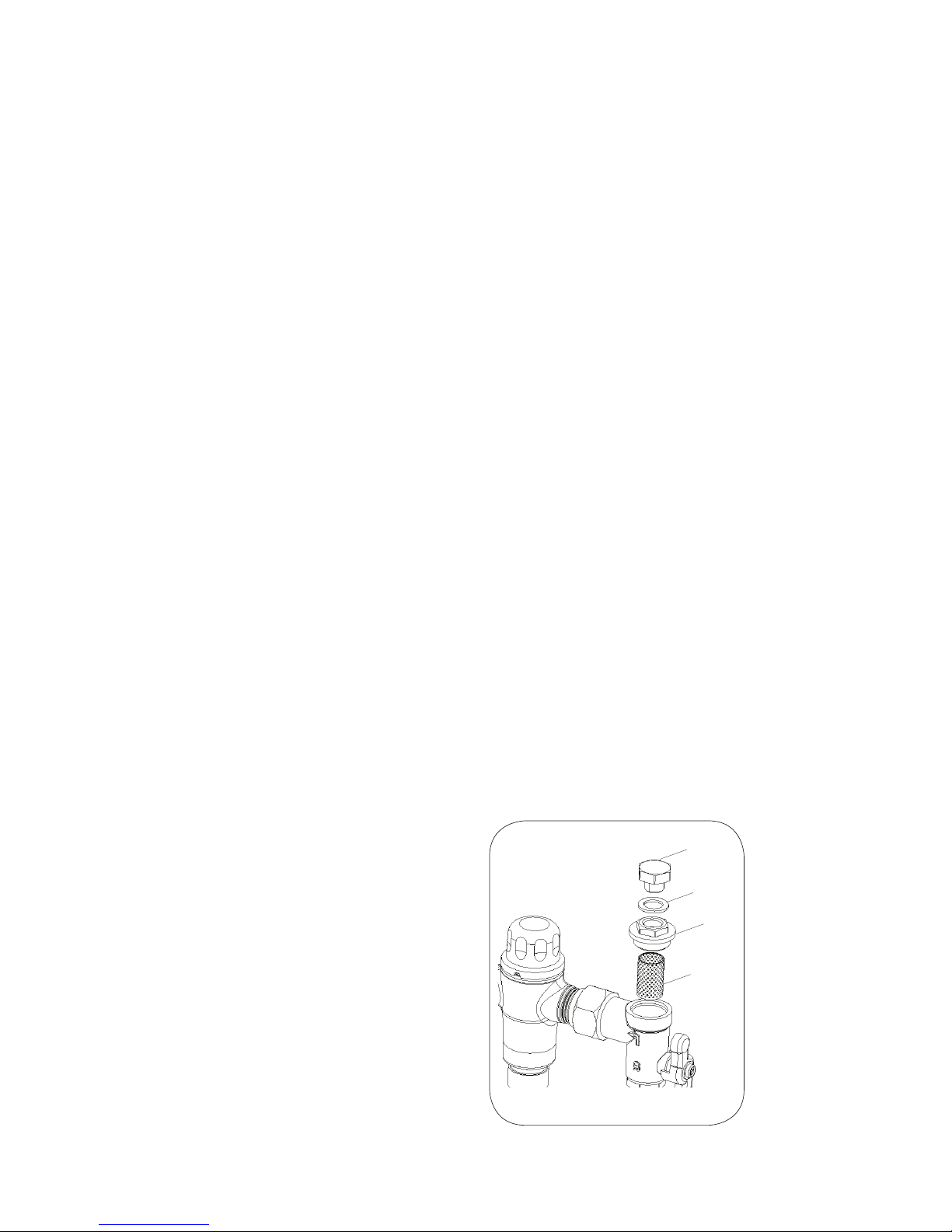
• Remove the inlet tting top cover with a suitable spanner and
then remove the mesh strainer, as shown in Figure 8
• The strainers should be cleaned with a dilute water solution
of suitable descaling solvent (such as CLR), checked for
physical damage and then thoroughly rinsed with clean water
• The strainers can then be re-installed into the inlets and the
top cover returned and tightened
to a maximum torque of 15Nm
into the inlet valve bodies.
Check that the test plug in the
top of the inlet ttings are tight,
then re-open the Isolating valves
and check there is no evidence
of water leakage
STRAINER
INLET TOP CAP
INLET TEST
PORT CAP
NYLON WASHER FOR
TEST PORT CAP
Figure 8
Page 16

www.enware.com.au Call 1300 369 273 16
B) Non-Return Valve Operation
Check Non-Return Valves on the HOT inlet side - visual
inspection.
• Turn OFF the isolation tap on the HOT inlet only (COLD inlet
must be open)
• Open Test Port Cap on the HOT inlet side
• Observe water level in the HOT inlet side test port. If there
is a rising water level this may indicate a fouled or faulty NonReturn Valve - replace if required
• Replace the test port cap on HOT inlet side ensuring it is
tighly secured
• Turn back ON the isolation tap on the HOT inlet
Check Non-Return Valves on the COLD inlet side repeating
steps above using the COLD inlet side.
C) Discharge temperature measured at the nearest outlet
to the valve for high and low ow
D) The cold water shut-off operation
E) The hot water shut-off operation
Where a device is not functioning in accordance with the
application requirements, the problem shall be rectied or the
device replaced - refer to the Troubleshooting on page 17.
The valve piston ‘O’ ring and thermostatic element/piston
assembly must be replaced at intervals not exceeding 5
years.
Page 17

17 Call 1300 369 273 www.enware.com.au
TROUBLESHOOTING
FAULT/
SYMPTOM
CAUSE RECTIFICATION
The desired
mixed water
temperature
cannot be
obtained
or valve is
difcult to
set
• Hot and cold supplies
are tted to the wrong
connections
• Valve contains debris
• Strainers contain debris
• Non-return devices are
damaged
• Top Cap and/or Piston
O-rings are damaged
• Ret the valve with Hot/
Cold supplies tted to the
correct connections
• Clean the valve ensuring
that all debris is removed
and components are not
damaged
• Clean strainers ensuring
debris is removed
• Check non-return device
is not jammed.Clean it if
necessary
• Check Top Cap & Piston
O-rings for damage.
Replace if necessary
The valve
will not shut
down
• The hot to mix temperature
differential is not 10°C or
greater
• The piston O-ring is
damaged
• Valve body seat (Hot Seat
is damaged or fouled by
debris
• Cold seat (bottom surface
of Top Cap) is damaged
• Thermostatic element has
failed
• Plastic shuttle of
Thermostatic element has
been damaged by debris
• Raise hot water
temperature
• Replace piston O-ring
• Clean seat using mild
descaling solution
• Replace top cap
• Replace element
Mix
temperature
unstable
• Debris is fouling valve
• Flow rate below 2L/min
• Strainers are fouled
• Clean valve ensuring
all debris is removed &
components aren’t damaged
• Rectify any pressure
deterioration. Increase ow
rate to minimum of 4 litres/
min
• Clean strainers
Mix
temperature
changing
over time
• Inlet conditions (pressures
or temperatures) are
uctuating
• Strainers contain debris
• Install suitable pressure
control valves to ensure
inlet conditions are within
those stated on Page 7
• Clean strainers ensuring
debris is removed
Page 18

www.enware.com.au Call 1300 369 273 18
TROUBLESHOOTING
FAULT/
SYMPTOM
CAUSE RECTIFICATION
Either full
hot or cold
owing from
outlet xture
• Valve is incorrectly set.
• Hot/Cold water has
migrated to other inlet
• Refer also to fault/symptom
1 & 2
• Adjust mix temperature
between 38 - 50°C as
required
• Replace faulty non-return
valves
No ow from
the valve
outlet
• Hot or cold water failure
• Strainers are fouled
• Valve functioning correctly
- shut down due to inlet
supply failure. Restore inlet
supplies and check mix
temperature
• Clean strainers
Flow rate
reduced or
uctuating
• Valve or inlet ttings fouled
by debris
• Dynamic inlet
pressures are not within
recommended limits
• Check valve and inlet
ttings for blockages
• Ensure operating conditions
are within specied limits
and the dynamic inlet
pressures are nominally
balanced to within +/- 10%
Mixed water
temperature
too hot or
cold
• Valve has been tampered
with
• Valve incorrectly set
• Inlet temperatures are not
within specied limits
• Readjust valve to required
set temperature
• Readjust valve to required
set temperature
• Ensure inlet temperatures
are within the specied limits
as listed on Page 7
Mixed water
temperature
not changing
when the
temperature
adjuster is
altered
• Return spring is missing
• Thermostatic element has
failed
• Install return spring
• Replace piston/thermostatic
element
Mixed water
temperature
adjuster
difcult to
move
• Adjuster at maximum mix
temperature stop
• Valve piston into overstroke
• Mixed water is at maximum
temperature. No higher mix
temperature adjustment is
available
• Wind adjuster out until set
temperature required is
achieved
Hot water
ows into the
cold water
system or
vice versa
• Non-return valve • Replace non-return valves
Valve is noisy • Water velocity above
velocity requirements of
AS3500.1 Sec 3.4
• Reduce water velocity
Page 19
19 Call 1300 369 273 www.enware.com.au
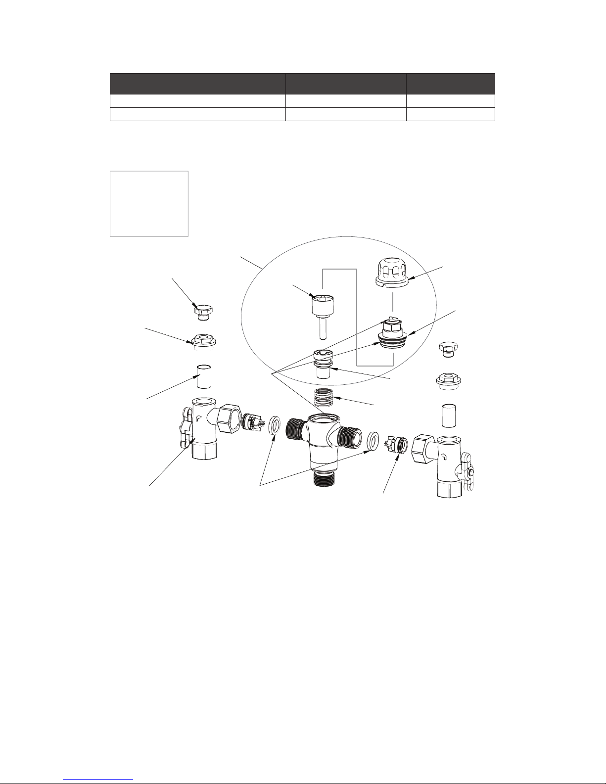
SPARE PARTS
Face Seals
ATMS213
Non-Return Valve (Each)
ATMS212
Inlet Fitting
Control Valve
3/4” FI Hot - ATMS705
3/4” FI Cold - ATMS703
1/2” MI Hot - ATMS501
1/2” MI Cold - ATMS502
Inlet Fitting
Strainers (Pair)
ATMS205
Inlet Cap to suit ATMS238
(Each)
ATMS244
Pressure Test Point Plug
With O-Ring (Pair)
ATMS238
Element and Piston
Assembly
O-Ring Kit
ATMS123
Lock Shield
Top Cap Assembly
OLD STYLE
Pressure Test Point Plug
With Washer (Each)
ATMS1314
Pressure Test Point
Washer Only (Each)
ATMS1204
Mixing Tube
Return Spring
ATMS190
5 YEAR
SERVICE KIT
ATMS242
PART REPLACEMENT TIME PART NUMBER
5 Year Service Kit (includes o-rings) 5 years ATMS242
O-Ring Kit when required ATMS123
Page 20

www.enware.com.au Call 1300 369 273 20
COMMISSIONING REPORT
Enware Thermostatic Mixing Valve Commissioning Report For
Thermostatic Mixing Valves use a separate sheet for each valve
Establishment
Address
Phone No Contact
Date
Work Order
No.
Make & Model of Hot Water Unit
Hot Water
Pressure
kPa
Cold Water
Pressure
kPa
Temp
˚C
Temp
˚C
Cold Water
Supply via
Pressure
Reducing
Valve Fitted
YES/NO
Make of
Mixing Valve
Model No
Size
Valve Location
/ Building
Valve ID No.
Total No. of
Mixing Valves
on Site/
Building
Total No. of
outlets served
by this valve
Baths Basins Showers
Other outlet details
Valve installed to requirements of
The drawing &
specication
The valve
manufacture /
supplier
The code of
TMV’s
The local water
supply authority
YES/NO YES/NO YES/NO YES/NO
If NO, give details and action taken
Page 21
21 Call 1300 369 273 www.enware.com.au
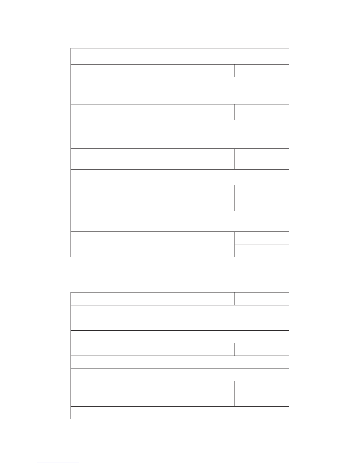
Test results (complete table on following page)
Valve considered satisfactory for use YES/NO
If NO, state reason and action taken
It is hereby certied that all the commissioning work has been
carried out by the undersigned in accordance with local plumbing
requirements for Thermostatic Mixing Valves
Date initial service due: (Maximum
12 months use)
Valve commissioned by:
Signature Licensed Plumber
Lic/Cert No
Business name of Plumbing
Contractor
Contractors Authority No
Date
NOTE: A duplicate copy of this report is to be retained at the site
for any inspection by authorised persons.
The following information is to be provided by site manager/owner:
Valve size and installation recommended by (name)
Valve supplied by (name)
Valve installed by (name)
Date of installation: Drawing No:
Certicate of Compliance/Inspection No: Dated:
Service manual on site: YES/NO
Report received by (name)
Position
Signature Date:
For and on behalf of the client/site manager/owner
Page 22

www.enware.com.au Call 1300 369 273 22
Test results
Valve location/building
Room or area designation
Work Order No
Warm
water
outlet
xture
No.
Name/type/
size & location
of outlet xture
(bath, shower,
basin or other)
Flow rate of design
warm water (L/sec)
Temp of warm water
°C
1 outlet
in use
** All req.
outlets in
use
1 outlet
in use
** All req.
outlets in
use
1.
2.
3.
4.
5.
6.
7.
8.
Give details of brand and model designation. Commensurate with the
design ow rate for the mixing valve.
NOTE: An accurate digital type thermometer is necessary for the temperature measurements.
Prescribed temperature range for warm water °C to °C
Fail safe at both minimum and maximum
design ow rates
PASSED/FAILED
Signature of licensed plumber
Licence/Cert No
Business name of plumbing contractor
Contractor’s authority No: Date:
Page 23
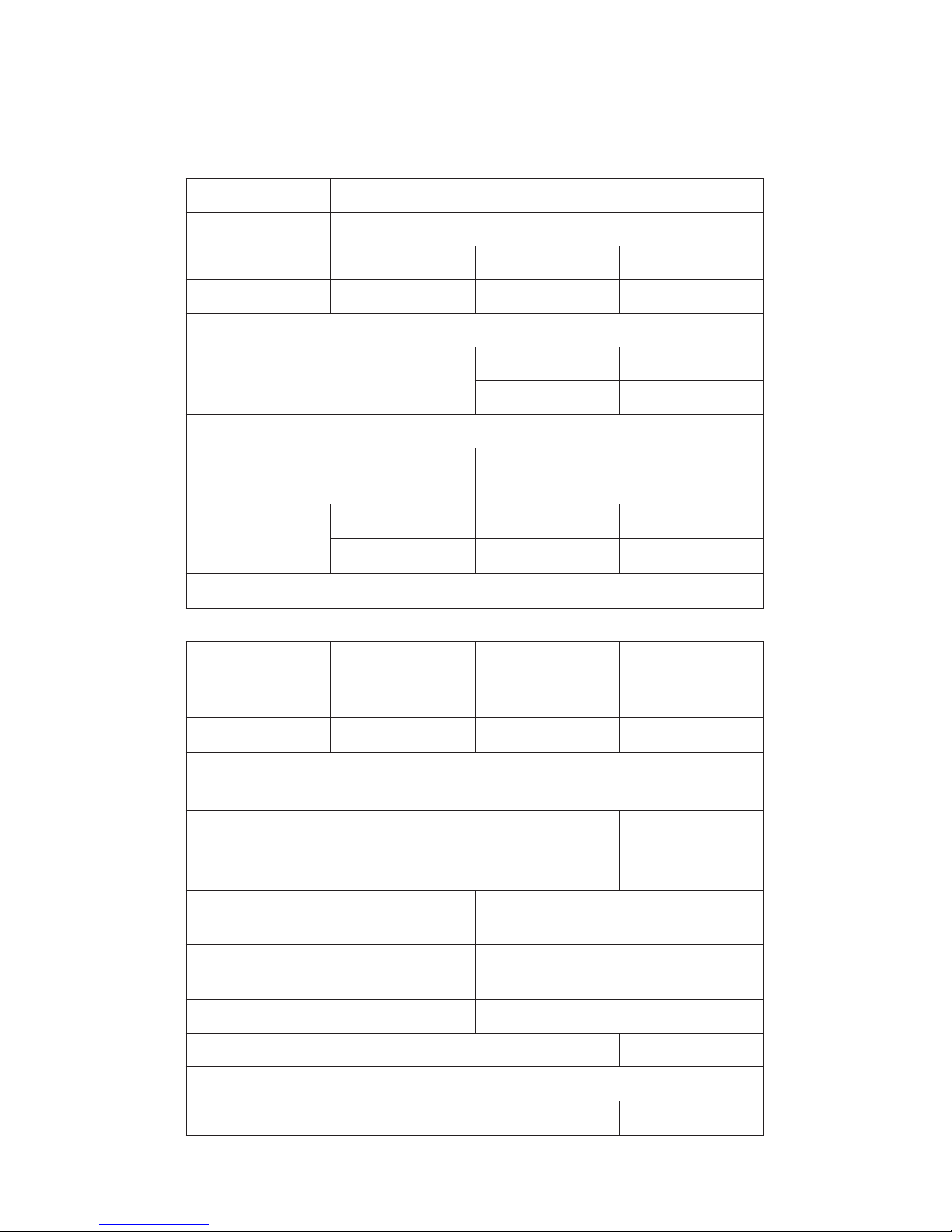
23 Call 1300 369 273 www.enware.com.au
SERVICING REPORT
Enware Thermostatic Mixing Valve Servicing Report
use a separate sheet for each valve
Establishment
Address
Phone No Contact
Date Work Order No.
Make & Model of Hot Water Unit
Mixing Valve Make:
Model No:
Size
Valve Location / Building
Valve ID No.
Total No. of Mixing
Valves on Site/ Building
Total No. of
outlets served
by this valve
Baths Basins Showers
Other outlet details
Valve installed to requirements of:
The drawing &
specication
The code of
TMV’s
The code of
TMV’s
The local
water supply
authority
YES/NO YES/NO YES/NO YES/NO
If NO, give details and action taken
Any current complaints concerning installation or
operation reported or stated in previous report
If YES, give details:
YES/NO
Particulars of service work
carried our during this visit
List of items replaced (and part
numbers) during this visit:
Warm water temp. at outlet °C Fail Safe Test PASSED / FAILED
Valve considered satisfactory for further use YES/NO
If NO, reason and action taken:
Date next service due (12 months maximum):
Page 24

www.enware.com.au Call 1300 369 273 24
It is hereby certied that all the commissioning work has been
carried out by the undersigned in accordance with local plumbing
requirements for Thermostatic Mixing Valves
Signature Licensed Plumber
Lic/Cert No
Business name of Plumbing
Contractor
Contractors Authority No
Date
NOTE: A duplicate copy of this report is to be retained at the site
for any inspection by authorised persons.
The following information is to be provided by site manager/owner:
Valve size and installation recommended by (name)
Valve supplied by (name)
Valve installed by (name)
Date of installation: Drawing No:
Certicate of Compliance/Inspection No: Dated:
Service manual on site: YES/NO
Report received by (name)
Position
Signature Date:
For and on behalf of the client/site manager/owner
Page 25

www.enware.com.au Call 1300 369 273 25
Appendix 1 - The Pressure Loss Ratio Calculation
At all times the conditions at the valve must be within
the specied pressure loss ratio to ensure that the outlet
temperature remains within the stated limits.
Pressure Loss Ratio is determined as follows:
At the valve, the difference between the cold inlet pressure
and the outlet pressure (back pressure) under ow conditions
is the pressure loss across the cold side. Similarly for the hot
side. The ratio of the larger pressure loss over the smaller
pressure loss gives the pressure loss ratio. For example, with
a cold supply pressure of 500 kPa, a hot supply pressure
of 250 kPa and a back pressure of 200 kPa (under ow
conditions), the pressure loss ratio is
= (cold pressure - back pressure) / (hot pressure - back
pressure)
= (500 - 200) / (250 - 200)
= 300 / 50
= 6 : 1 pressure loss ratio
Note - the inlet supply pressures alone will not give an
accurate indication of the pressure loss ratio! (In this case a
2:1 inlet supply pressure ratio is actually a 6:1 pressure loss
ratio under ow conditions.)
Note also - the static supply pressures give absolutely
no indication whatsoever of the pressure loss ratio. Only
pressures under ow conditions should be used to calculate
pressure loss ratio.
Page 26

26 Call 1300 369 273 www.enware.com.au
PRODUCT WARRANTY
The ENWARE AQUABLEND 2000 Thermostatic Mixing Valve
is guaranteed free from manufacturing defects for a period of
24 months*, subject to the conditions outlined below:
Enware Product Warranty
Subject to the warranty conditions and exclusions set out
below ENWARE valves are warranted to be free from defects
in material and/or workmanship for a period of 24 months
service life and if found by ENWARE to be so defective will be
replaced as set out below. If the valve is sold by a party other
than ENWARE then it is sold by that seller as principal and the
seller has no authority from ENWARE to give any additional
warranty on behalf of ENWARE.
The benets of this warranty are in addition to all other rights
and remedies which the purchaser may have under the Trade
Practices Act (Cwth) or similar laws of each State and Territory
in Australia.
Warranty Conditions
The valve must have been installed by a licensed plumber
in accordance with the ENWARE Installation Instructions
and Application Guidelines supplied with the valve, and in
accordance with the National Plumbing and Drainage Code
AS3500 (the Code) current at the date of installation and
all relevant statutory and local requirements in the State or
Territory in which the valve is installed.
Where the valve is installed outside the boundaries of a
metropolitan area as dened by ENWARE, the cost of
transport insurance and travelling shall be the purchaser’s
responsibility. (Refer to the ENWARE scale of fees for
replacement of valves).
Where the valve comprises part of a hot water system,
installation of that system must be in accordance with its
manufacturer’s recommendations, the Code and all relevant
statutory and local State or Territory requirements.
* 5 Years Conditional Warranty: 2 years parts and labour on the complete
assembly; an additional 3 years parts supply only on the valve body excluding
inlet tting assemblies.
Page 27

www.enware.com.au Call 1300 369 273 27
The valve must be returned to ENWARE with a fully &
correctly completed ENWARE Warranty Claim Form.
Where the valve is replaced under warranty the replacement
valve carries a new warranty as detailed herein.
Warranty Exclusions
Replacement work will be carried out as set out in the
ENWARE Warranty above, but the following exclusions may
cause the warranty to become void, and may incur a service
charge including cost of parts where:
Damage has been caused by accident, Acts of God, misuse,
incorrect installation of the hot water system of which the valve
forms a part or attempts to disassemble the valve.
It is found that there is nothing wrong with the valve.
The failure of the valve is due in part or in whole to faulty
manufacture/installation of the hot water system of which the
valve forms part.
The valve has failed directly or indirectly as a result of
excessive water pressure or temperature outside the
Application Guidelines, thermal input or corrosive environment.
The valve has failed due to foreign matter either from
installation or the water supply.
The failure of the valve is due to scale formation in the
waterways of the valve.
The failure of the valve is due in part, or in whole, to
installation not in conformance with the requirements of the
Code.
ENWARE reserves the right to change its specications
without prior notice and will not accept liability for any claim
arising from such change.
Subject to any statutory provisions to the contrary, claims for
damage to furniture, carpets, walls, foundations or any other
consequential loss either directly or indirectly due to leakage
from the valve are also excluded from warranty cover.
Page 28
 Loading...