

Page 1

Operational
Manual
Manual for the unit:
MT 1500
MT 1800
MT 2300
MT 3200
MT 4500
MT 5500
MT 6000
ENWA AB
Backa Bergögata 13, SE-422 46 Hisings Backa
Tel. +46 (0)31-742 92 50, Fax. +46 (0)31-742 92
[email protected] - www.enwa.se
Page 2

ENGLISH
Version 041027
CONTENTS
1. INTRODUCTION ........................................................... 2
2. DESCRIPTION OF PROCESS...................................... 3
3. SPECIFICATION ........................................................... 5
4. INSTALLATION FOR SPLIT MOUNTED UNIT ............. 6
5. INSTALLATION FOR RACK MOUNTED UNIT ............. 9
6. INITIAL START-UP PROCEDURE.............................. 11
7. NORMAL START-UP .................................................. 13
8. NORMAL STOP........................................................... 14
9. LONG TERM STOP..................................................... 15
10. GENERAL RUNNING AND OPERATION CONDITION18
11. R.O-MODULE FOULING............................................. 19
12. CHEMICAL CLEANING AGENTS ............................... 23
13. TROUBLE SHOOTING................................................ 26
14. MAINTENANCE............................................................27
1/28
Page 3

ENGLISH
Version 041027
1. INTRODUCTION
The Reverse Osmosis desalination unit described in this manual is one of a range of fresh
water units available to produce potable water from brackish water or sea water with a
TDS (salt content) up to 42.000 mg/l (4,2 %).
To ensure proper operation, the unit has to be operated with feed water free from organic
contamination such as oil, grease etc. The turbidity (suspended matter) of the feed water
has to be lower than 0,5 NTU. Only open sea water is permitted, harbour water can
contain up to 40 NTU suspended matter.
If the unit is intended to be operated on feed water with a suspended matter higher than
0,5 NTU, or if oil, grease etc. is present an additional pre-treatment section is required.
For information, please contact ENWA AB.
2/28
Page 4

ENGLISH
Version 041027
2. DESCRIPTION OF PROCESS
The treatment section is carried out in two stages:
- Pre-treatment.
- Desalination with Reverse Osmosis.
PRE-TREATMENT:
This stage of the process is designed to remove larger varieties of contaminants that would
otherwise interfere with the short and long term performance of the reverse osmosis
membranes.
Feed water enters the unit through a mesh filter (not shown on the diagram). The mesh
filter absorbs large particles that would plug feed pipes or cause damage to the pump. This
filter will not be included the delivery from ENWA AB. Recommended mesh size is 0,52,5 mm. The mesh filter supplied has to be manufactured from a non-corrosive material.
The feed water will then continue to the feed water pump which increases the feed water
pressure to 1,5 - 2,5 bar, but can under some circumstances be higher or lower.
A feed water valve (HV-2010) controls the feed water supply from the mesh filter and a
check valve (CV-2010) will ensure that flushing water not will flow backwards through
the feed water pump. The feed water will then continue to the feed water filter (F-2010)
and you can see the pressure on the pressure indicator (PI-2011).
The flush water filter (F-2020) contains an activated carbon cartridge, the purpose of the
filter is to de-chlorinate the flushing water from the storage. These filters will absorb
suspended matter larger than 10 micron size.
DESALINATION WITH REVERSE OSMOSIS
The feed water will then continue to the high-pressure pump (HPP-2010) that will
increase the feed water pressure to normal operation pressure (See general operation
conditions). After the high pressure pump the feed water continues to the R.O-module
(RO-2030, eventually -31, -32, -33, -34) that desalinates the water.
Two streams will pass out from the module; one is product and the other one is brine (salt
concentrate). The brine will continue to the pressure regulating valve (PCV-2050) which
by opening or closing will decrease respectively increase the operation pressure. Actual
operational pressure is shown on the pressure indicator (PI-2050) upstream the R.Omodule. The brine will then continue to sea as waste.
The product from the R.O-module will pass through a conductivity-cell that measures the
conductivity in the product water. The conductivity meter (1u400) will influence the
solenoid valve (ROV-2060) that divides the product water to tank or waste. If the
3/28
Page 5

ENGLISH
Version 041027
conductivity is below the limit, the product will go to tank and if the conductivity is above
the limit, the product will go to waste.
When the conductivity meter is in ”OFF” position the product water will go to waste.
The product flow will be measured by a flow-meter (FI-2060).
4/28
Page 6

ENGLISH
Version 041027
3. SPECIFICATION
FEED WATER:
Clean sea water, approx. 10-15 litres/min.
VOLTAGE PHASE FREQUENCY POWER FP POWER HP
115 VAC 1-phase 60 Hz 0.55 kW 1.1 kW
230 VAC 1-phase 50 Hz 0.55 kW 1.5 kW
400 VAC 3-phase 50 Hz 0.55 kW 1.5 kW *
440 VAC 3-phase 60 Hz 0.55 kW 1.8 kW
*MT 6000 2.2 kW
WATER CONNECTIONS:
SPLIT MOUNTED:
Inlet feed water CN-2010 20 mm Hose nipple.
Inlet flush water CN-2020 3/8” Plastic tube.
Outlet product CN-2060 3/8” Plastic tube.
Outlet product to waste CN-2050 3/8” Plastic tube.
Outlet brine to waste CN-2050 3/8” Plastic tube.
RACK MOUNTED:
Inlet feed water CN-2010 3/8”R Inside.
Inlet flush water CN-2020 3/8”R Inside.
Outlet product CN-2060 3/8”R Inside.
Outlet waste CN-2050 3/8”R Inside
WATER PRESSURE:
Feed water Min. 1,5 bar. Max. 4,0 bar.
Flush water Min. 2,0 bar. Max. 4,0 bar.
Product water Max. back pressure 2,5 bar.
FEED WATER TEMPERATURE:
Design 25° C.
Min. 0° C.
Max. 45° C.
5/28
Page 7

ENGLISH
Version 041027
4. INSTALLATION FOR SPLIT MOUNTED UNIT
The pump module and R.O-module may be mounted next to each other, or separately as
desired.
FEEDWATER PUMP (FP-1010, Option)
Mount the pump below sea level. A washable mesh filter should be connected in the
suction side of the pump. The fittings and hose must be of non-corrosive material. (A
plastic hose with stainless hose clamps is suitable).
FILTER MODULE (Flush water filter, Feed water filter)
The filter bracket must be secured attached to a rigid surface. Be sure to allow space for
filter air venting and cartridge replacement. Also note that the flush water filter has to be
connected to the existing fresh water system and a carbon cartridge filter must be used in
the filter.
PUMP MODULE (HPP-2010)
When the high-pressure pump (HPP-2010) is driven by an electric motor there must be
sufficiently ventilation in order to transfer the waste heat from the electric motor. The
pump module must be mounted horizontally upon a rigid base. To avoid vibrations, rubber
mounting shall be used between base plate and the rigid base.
There should be ample room around the unit for its operation and for the following
maintenance:
1 - Valve- and sealing changes, and also belt changes (when V-belting).
2 - Oil change.
3 - Pump service.
4 - Electrical hook-up.
6/28
Page 8

ENGLISH
Version 041027
R.O-MODULE (RO-2030 eventually -31, -32, -33, -34)
The R.O-module can be bolted or screwed to a horizontal or vertical surface.
The location chosen should:
1 - At no time have a surrounding temperature exceeding 45° C.
2 - Have adequate space around for operation and maintenance such as adjustment
of working pressure and safety relief valve.
3 - Not be mounted where unforeseen leakage can cause damage.
PRODUCT FLOW METER (FI-2060, option)
Shall be mounted vertically according to the flow diagram.
HOSE CONNECTIONS
To connect all items to each other, see process and connection diagram.
BRINE OUTLET TO WASTE
The brine outlet must be led off above the sea level.
PRODUCT WATER TO TANK
The product from the unit must be led to the fresh water storage tank.
PRODUCT WATER TO WASTE
The product to waste shall be located so that no seawater or other contaminated water can
flow backwards after shut down of the unit. When the unit is stopped air will flow
backwards into the R.O-modules to prevent vacuum in the system.
NOTE! Do not close the valve if installed on the pipe to tank or waste. If the unit is operated
against a closed pipe the pressure will increase until the pipes of the system breaks.
FLUSH WATER
When the unit is stopped fresh water has to flush the system clean from seawater. Connect
a pipe (hose) from the fresh water pressure system (cold water) to the flush water valve
upstream the flush water filter.
7/28
Page 9

ENGLISH
Version 041027
CONDUCTIVITY CELL (1u400) AND 3-WAY SOLENOID VALVE (ROV-2060)
Shall be mounted within reach for service and manual activation on a rigid surface with
the 3-way solenoid valve above the cell.
ELECTRIC CONTROL UNIT
All electrical control units shall be mounted on a rigid surface. Allow space for operation.
ELECTRICAL CONNECTIONS
To connect all electrical items, see process and connection diagram as well as electrical
diagram.
NOTE! Mount an operate/safety switch for the electrical connections to the unit.
8/28
Page 10

ENGLISH
Version 041027
5. INSTALLATION FOR RACK MOUNTED UNIT
DESALINATION UNIT
The desalination unit must be bolted horizontally where the location chosen should:
1. At no time have a surrounding temperature exceeding 45° C.
2. Have adequate space around for operation and maintenance.
3. Not be mounted where unforeseen leakage can cause damage.
NOTE! Lift the unit/parts in the steel frames or consoles.
FEEDWATER PUMP (FP-1010, option)
Mount the pump below sea level. The suction or inlet side of the pump should be
connected to a washable mesh filter. The fittings and hose must be of non-corrosive
material (a plastic hose with stainless hose clamps is suitable).
PRODUCT WATER TO TANK (CN-2060)
The product from the unit must be led to the fresh water storage tank.
BRINE AND PRODUCT WATER TO WASTE (CN-2050)
The brine/product to waste shall be located so that no seawater or other contaminated
water can flow backwards after shut down of the unit. When the unit is stopped, air will
flow backwards into the R.O-modules to prevent vacuum in the system.
NOTE! Do not close the valve if installed on the pipe to tank or waste. If the unit is operated
against a closed pipe the pressure will increase until the pipes of the system breaks.
FLUSH WATER (CN-2020)
When the unit is stopped fresh water has to be used to flush the system clean from
seawater. Connect a pipe (hose) from the fresh water pressure system (cold water) to the
flush water connection.
NOTE! A carbon cartridge filter must be mounted in the flush water filter.
9/28
Page 11

ENGLISH
Version 041027
ELECTRICAL CONNECTIONS
To connect all electrical items, see process and connection diagram as well as electrical
diagram.
NOTE! Mount an operate/safety switch for the electrical connections to the unit.
10/28
Page 12
ENGLISH
Version 041027
6. INITIAL START-UP PROCEDURE
Carry out the following steps the first time the fresh water unit is to be operated, or after a
prolonged shut down.
1. Check the oil level on the high-pressure pump (HPP-2010).
Check that the cartridge filters (F-2010, -2020) are properly installed.
2. Check the position on the following valves:
• Manual flush water valve (HV-2020) open
• Pressure regulating valve (PCV-2050) open
• Bottom valve sea water intake open
• Brine outlet, (if installed) open
• Product to waste, (if installed) open
• Tank valve, (if installed) open
3.
• Open the feedwater valve (HV-2010).
• Start the feedwater pump (FP-1010) by the switch marked ”SYSTEM”.
• Start the high-pressure pump (HPP-2010) by turning the switch marked
”HP PUMP” into position ”AUTO”.
NOTE! If feedwater pressure decreases to less than 0,5 bar, the unit will
stop by the low pressure switch (PLCO-2010).
4. Stop the conductivity meter (1u400) by turning the switch marked ”SALINITY”
to “OFF” position. The product will then automatically go to waste since the
ROV-2060 is no activated.
5. Wait until the system is filled by feed water and becomes stabilised.
Adjust the operate pressure as recommended in ”GENERAL RUNNING
AND OPERATION” by turning the valve knob on the pressure regulating
valve (PCV-2050) slowly clockwise.
6. Operate the unit in this position (product water to waste) at least one hour. This
procedure flushes the unit free from chemicals etc.
Check for leaks at the same time.
11/28
Page 13

ENGLISH
Version 041027
7. Start the conductivity meter (1u400) by turning the switch marked
“SALINITY” to position “ON”. When the conductivity is below 1200
µS/cm the product will automatically go to tank (ROV-2060 will be
activated.
8. For shut down, see ”NORMAL STOP”.
NOTE!
For initial start-up after a prolonged shutdown, or after any chemical treatment, the unit must be
started according to the instructions in ”INITIAL START-UP PROCEDURE”.
12/28
Page 14

ENGLISH
Version 041027
7. NORMAL START-UP
After the unit has been initially started and flushed, the subsequent steps are to be made:
• Check that the flush water valve (HV-2020) is open.
• Open the feedwater valve (HV-2010).
• Start the feedwater pump (FP-1010) by the switch marked ”SYSTEM”.
• Start the high pressure pump (HPP-2010) by turning the switch marked ”HP
PUMP” into position ”AUTO”.
NOTE
stop by the low pressure switch (PLCO-2010).
Adjust the operate pressure as recommended in ”GENERAL RUNNING AND
OPERATION”.
! If feedwater pressure decreases to less than 0,5 bar the unit will
NOTE!
If the unit has been shut down for more than two days, run the first amount of product water to
waste for at least 15 minutes. Close the conductivity meter (1u400) by turning the switch marked
“SALINITY” to “OFF” position. The product will then automatically go to waste since the ROV-2060
is not activated.
13/28
Page 15

ENGLISH
Version 041027
8. NORMAL STOP
To shut down the unit, proceed as follows:
• Turn the switch marked ”HP PUMP” to ”OFF” position
• Turn the switch marked ”SYSTEM” to ”OFF” position.
• The flush water valve (ROV-2020) opens automatically for appr. 10-15 min.
(The flush water valve closes automatically).
NOTE!
If it is desired to shut down the desalination unit for less than one (1) week, the above steps are all
that is required. However, if the desalination unit is to be shut down for over one week, it should be
flushed weekly as above. Or if the unit is equiped with automatic flushing it will flush automatically at
100 hours shutdown. (preset from factory)
SHUT-DOWN FOR A LONG PERIOD
If the unit is to be shut down for a considerable length of time, over one (1) week, or when
the automatic flush system is not in operation, it should be preserved to prevent bacterial
or marine growth. Follow the procedure given under the section ”LONG TERM STOP”.
14/28
Page 16

ENGLISH
Version 041027
9. LONG TERM STOP
The R.O-module should be preserved with MT-5 solution when it is intended to shut
down the desalination unit for a long period, or when it not can be flushed regularly every
week.
We have cleaning equipment as extra equipment, alternative you can use a portable
cleaning tank and plastic hoses.
1. Shut down the unit as described under “NORMAL STOP”.
2. Loose the product water connection (product hose) to tank (CN-2060).
NOTE! Do not remount the product hose to tank during the whole preservation.
Connect another plastic hose and connect the other end of the hose to a 40 litres
cleaning tank (plastic bin).
On units with chemical cleaning equipment you turn the 3-way valve for the
product water (CCV-2060) in position open to the cleaning tank for chemical
cleaning.
3. Start the unit as described under ”NORMAL START” and produce 40 litres of
product water in the plastic bin. Stop the unit.
4. Close the conductivity meter (1u400) by turning the switch marked “SALINITY”
in position “OFF”. The product will then automatically go to waste since ROV2060 are not activated
NOTE! Units equipped with optionally conductivity meter, will route the product flow to waste,
when turning the switch marked ”SALINITY” to ”OFF” position.
5. Pour one plastic bottle of MT-5 solution into the plastic bin containing 40 litres of
product water. Mix with a clean stick.
6. Close the manual flush water valve (HV-2020).
7. Close the bottom valve upstream mesh filter.
8. Loose the plugged connection CN-2015) and connect a plastic hose and lead the
other end of the hose to the cleaning tank that now contains 40 litres of
preservation solution.
On units with chemical cleaning equipment you will turn the 3-way valve for the
feed water (CCV-2055) to position open to cleaning tank for chemical cleaning.
9. Check that the feedwater valve (HV-2010) is closed.
On units with chemical cleaning equipment, the feed water valve (HV-2010) must
be open.
10. Open the pressure-regulating valve (PCV-2050) fully.
15/28
Page 17

ENGLISH
Version 041027
11. Do not start the feedwater pump.
16/28
Page 18
ENGLISH
12. Start the high-pressure pump (HPP-2010) in position “MAN”.
Version 041027
NOTE! The pump will throb until the flow-and-pressure in the system becomes stabilised.
14. Do not flush the system after preservation.
(The preservation solution will be flushed away in that case).
15. Reconnect the feedwater connection (CN-2010).
16. Switch the main power switch to ”OFF” position.
NOTE 1: To provide protection against freeze damage, disconnect the R.O module and store it in
an ambient temp. between 0-35 C, and also free drain pumps and pipes from water.
NOTE 2: When the unit is to be restarted, follow the steps under
”INITIAL START-UP”.
NOTE 3: Maximum allowed preservation time with MT-5 is 1 year. If the unit has the intention to
be shut down for a longer period than 1 year, the unit must be preserved again as above.
WARNING 1
The use of chlorine or quaternary ammonium chloride types of conservation solution
is prohibited. The use of such chemical agents will cause irreparable loss of
productivity and gradual deterioration of the R.O module.
WARNING 2
The chemical liquid compound MT-5 must be handled with extreme care. It causes
irritation of skin, eyes, nose and throat. Avoid prolonged or repeated contact with
any part of the body. Do not inhale. Always use with adequate ventilation. If it comes
in contact with the skin or eyes, immediately rinse the affected parts liberally with
water for at least 15 min., and in case of the eyes, immediately seek medical aid.
17/28
Page 19
ENGLISH
Version 041027
10. GENERAL RUNNING AND OPERATION CONDITION
Maximum feed water temperature is 45° C.
Maximum feed water salt content 42000 mg/l (4.2%, approx. 60000 µS/cm)
(If the feed water salt content is more than 35000 mg/l the salt content in the
product water can be a little bit more than 500 mg/l, WHO’s recommendation)
Maximum operate pressure is:
115 VAC units 60 bar
All other units 65 bar
Normal operate pressure is 40-65 bar (40-60 bar in 115 VAC units) and depends on the
salt content and temperature in the feed water.
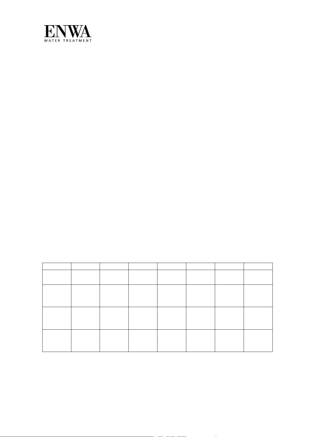
Maximum product flow depends on the type of unit as below.
Normal product flow depends on:
a. Type of unit
b. Feed water temperature
c. Salt content in the feed water
Low temperature and/or high salt content in the feedwater will decrease the
product water flow as below.
MT 1500 MT-2300 MT 1800 MT 3200 MT4500 MT 5500 MT 6000
Max.
Flow l/h
Normal
Flow l/h
T=25°C
Normal
Flow l/h
T=15°C
Normal
Flow l/h
T=5°C
The table is based on 30000 mg/l
60 95 75 135 185 225 250
60
45
29
95
75
54
75
58
41
(3.0%, 45000 µS/cm) salt content in the feed water.
135
104
75
185
150
110
225
185
145
250
205
160
18/28
Page 20

ENGLISH
Version 041027
11. R.O-MODULE FOULING
Is a complex phenomenon which involves trapping material in the fibre bundle or on the
surface of the membrane inside the R.O. module. When a R.O module fouls, the salt
concentration of the product water usually increases. The conductivity meter shows higher
conductivity. When it has reached an unacceptable level is it time for chemical treatment.
The following foulings are the most common:
- Scaling
- Metal oxides
- Particulate matter
- Colloids
- Biological matter
- Hydrolyse by chlorine
SCALING
Scaling is caused by the precipitation of sparingly soluble salts as CaCO3 and CaSO4 in
the R.O-module. This phenomenon will happen, when the feedwater flow is too low
compared to the product water flow, and can be determined by measuring the brine flow
from the unit. The brine flow should exceed 8 litres/min.
The reason when the feedwater flow is to low is loose V-belt on the high-pressure pump.
See Belt Tensioning. The reason can also be a fouled pump valve. See high-pressure pump
in the component data sheet section.
METAL OXIDES
Fouling with metal oxides is caused by the formation of the oxide and/or the hydroxide of
iron, manganese or aluminium, but iron is the most common.
Iron fouling can be avoided by selecting the best non corrosive material on the feedwater
side of the unit. Also product storage and distribution system has to be of a non corrosive
material to avoid iron oxide entering the unit during flushing, after the unit has been
stopped.
Fouling by metal oxides is identified by rapid conductivity increasing (within 24 hours) to
a level of full scale on the meter.
19/28
Page 21

ENGLISH
Version 041027
PARTICULATE MATTER
Device plugging is caused by the mechanical filtration of particulate matter. That is too
large to pass through the feed - brine passage.
The average spacing in the membranes is about 20 microns. As a general rule, if a particle
is less than about 10 microns, it should be able to pass through a 20 microns passage. To
avoid particulate plugging, be sure that right micro cartridge is used (5 or 10 micron) and
is properly installed.
COLLOIDS
Colloidal fouling is caused by the coagulation of colloids in the R.O-module during the
reverse osmosis process. Colloids are very small particles usually ranging from 0,3 to 1,0
micron in size. To avoid colloidal fouling do not operate the unit in harbours and water
which is polluted.
If the unit is intended to be operated in such water, an extended pre-treatment section is
required. Contact ENWA AB. Colloidal fouling is identified by conductivity increasing
over several weeks.
BIOLOGICAL MATTER
Biological fouling can occur when the feedwater contains sufficient nutrients to sustain
rapid growth of organisms inside the R.O.module. This growth can lead to deposition of
slimes, causing R.O. module fouling and poor performance.
To avoid biological fouling do not operate the unit in water which is strongly
contaminated with bacteria. Such as harbour water etc.
If the unit is intended to be operated in such water, please contact ENWA AB, so that a
suitable pre-treatment section can be designed. Bacterial fouling is identified by
conductivity increasing after an extended shut down without MT-5 protection.
HYDROLYSE BY CHLORINE
If the unit is operated with water containing chlorine, a carbon filter has to be used as a
pre-treatment.
Chlorine, even in very week concentration will cause damage to the R.O. module.
Flushing water from the storage onboard can, under some circumstances contain chlorine
e.g. when the water tanks have been filled up with water shore which contains chlorine. It
is of highest importance that the carbon cartridge is properly installed in the filter house
for flush water
and has not been replaced by a normal cartridge filter.
Normal seawater does not contain any chlorine.
20/28
Page 22

ENGLISH
Version 041027
CHEMICAL CLEANING PROCEDURES
Reverse Osmosis, like most other water treatment equipment, occasionally needs cleaning.
As a separate item a cleaning tank is required. The tank can be a plastic bin containing a
volume of 40 litres. Some plastic hoses are also required.
CHEMICAL TREATMENT
1. Shut down the unit as described under ”NORMAL STOP”.
2. Disconnect the product water connection to tank (CN-2060).
NOTE! The connection to the tank is not allowed to be reconnected during
the whole cleaning procedure.
Connect another plastic hose and insert its other end into a cleaning tank of 40
litres volume (plastic bin). On units with chemical cleaning equipment turn the product
water cleaning 3-ways valve (CCV-2060) in position to cleaning tank.
3. Start the unit as described in ”NORMAL START” and let 40 litres of product
water be produced in the cleaning tank. Stop the unit as described in ”NORMAL
STOP”.
4. Close the bottom valve upstream mesh filter (if installed).
5. Disconnect the plugged connection (CN-2015) and connect a plastic hose and
insert its other end into the cleaning tank containing the 40 litres of product water.
On units with chemical cleaning equipment turn the feed water cleaning 3-valve
(CCV-2055) in position to cleaning tank.
6. Disconnect the brine water connection (CN-2050) and connect another plastic
hose and insert its other end into the cleaning tank containing 40 litres of product
water.
In units with chemical cleaning equipment turn the brine water cleaning 3-valve
(CCV-2050) in position to cleaning tank.
7. Prepare the chemical treatment solution to be used.
See ”CHEMICAL CLEANING AGENTS”.
8. Close the flush water valve (HV-2020).
9. Close the feedwater valve (HV-2010).
On units with chemical cleaning equipment the feed-water valve (HV-2010) must
be open.
10. Open the pressure-regulating valve (PCV-2050) fully.
11. Do not start the feedwater pump.
21/28
Page 23

ENGLISH
Version 041027
12. Start the high-pressure pump (HPP-2010) with “MAN” position
NOTE! The pump will throb until the flow and pressure in the system becomes stabilised.
13. Re-circulate the cleaning solution at least one hour.
The temperature of the cleaning solution must not exceed 40° C, if it should
happens, stop the high pressure pump and allow the solution to cool.
14. Stop the high-pressure pump (HPP-2010).
15. Flush the unit at least 15 min. with feed or fresh water.
For flushing with feedwater run the unit with fully open pressure regulating valve
and product water valve open to waste.
For flushing with freshwater open the flush water valve and keep the product water
valve open to waste.
16. Continue with the next type of cleaning or if the unit is intended to be in
service, reconnect all service hoses and start the unit as described in
”INITIAL START-UP PROCEDURE”.
WARNING !
For initial start-up after a prolonged shut-down, or after any chemical treatment,
allow the product water to flow to waste for at least 1 hour, by turning on the
product water 3-way valve to waste.
If the cleaning procedure has no effect, disconnect the R.O-module and send it to
ENWA AB, for cleaning.
22/28
Page 24

ENGLISH
Version 041027
12. CHEMICAL CLEANING AGENTS
When using any of the chemicals mentioned, follow accepted safety practice.
When preparing chemical solutions for cleaning, be certain that all chemicals are
dissolved and well mixed before introducing them into the R.O. unit.
During re-circulation, temperatures must not exceed 40° C.
All chemicals to be used for cleaning and treatment, must be handled with extreme care.
They cause irritation of skin, eyes, nose and throat. Avoid prolonged or repeated contact
with any part of the body. Do not inhale. Always use with adequate ventilation. In case it
comes in contact with the skin or eyes immediately rinse the affected parts liberally with
water, and in case of the eyes seek medical aid.
The fresh water to be used for the chemical treatment has to be free from chlorine. Normal
tap water has to be de-chlorinated by a carbon filter. Product water from the unit can be
used direct. Use gloves and protection glasses.
MT-10 CHEMICAL CLEANING
Shall be used as a general cleaning procedure when the product flow has decreased with
10-15 % below rated flow or the conductivity has increased to 1200 µS/cm.
On units equipped with conductivity control/alarm, the alarm will be released at 1200
µS/cm.
The MT-10 shall also be used as an ”pre-cleaning” before a sterilisation with MT-5
solution is done.
Preparing MT-10
Add one plastic bottle of MT-10 into the 40 litres cleaning tank containing product water.
Mix well.
Re-circulation time MT-10
1 hour.
Best temperature for treatment is 30-35° C.
Lowest allowed temperature is 25° C.
Highest allowed temperature is 40° C.
Flush the unit free from cleaning solution during 15 min. with flush water.
If the unit is intended to be in service you must proceed as described in
”INITIAL START-UP PROCEDURE”.
If the unit is not intended to be in service it must be preserved as
described in ”MT-5 PRESERVATION”.
23/28
Page 25

ENGLISH
MT-10 + MT-5 STERILISATION
Sterilisation has to be done when the content of bacteria is too high, which you recognise
on a bad taste of the water. Pretreat the unit with MT-10 as described in ”MT-10
CHEMICAL CLEANING”. Flush for at least 15 minutes. After that you are going to treat
the unit as described in ”Preparing MT-5 Sterilisation”.
Prepare MT-5 Sterilisation
Mix one plastic bottles of MT-5 into the 40 litres cleaning tank containing product water.
Mix well.
Re-circulation time MT-5 Sterilisation
1 hour.
If the unit is intended to be in service you must proceed as described in ”INITIAL
START-UP PROCEDURE”.
If the unit is intended to be stored you must leave it with the MT-5 solution.
Do not flush the unit then.
MT-5 PRESERVATION
This solution shall be used when the unit will be out of service for more then 1 week and
you are not intended to flush it every week.
Prepare MT-5 Preservation
Add one plastic bottle of MT-5 to the 40 litres cleaning tank containing product water.
Mix well.
Version 041027
NOTE 1:The MT-5 solution must be in the unit during the preservation time (max. 1 year) so you
must not
proceed as described in ”INITIAL START-UP PROCEDURE”.
flush it after preservation. When the unit is intended to be in service again you must
NOTE 2:The unit is now preserved with MT-5 solution for 1 year. If the unit will be stopped more
than 1 year it must be re-preserved.
24/28
Page 26

ENGLISH
Version 041027
MT-20 CHEMICAL CLEANING
To be used when scaling or metal-oxides have caused fouling.
Preparing MT-20
Add one plastic bottle of MT-20 into the 40 litres cleaning tank containing product water.
Mix well.
Re-circulation time MT-20
1 hour.
Best temperature for treatment is 35° C.
Lowest allowed temperature is 25° C.
Highest allowed temperature is 40° C.
If the unit is intended to be in service you must flush the unit with flush water during 15
minutes.
Proceed with the ”INITIAL START-UP PROCEDURE”.
If the unit is intended to be shut down for a long period, flush it as above and then prepare
it as described in ”LONG TERM STOP”.
25/28
Page 27

ENGLISH
Version 041027
13. TROUBLE SHOOTING
LOW FEEDWATER PRESSURE
1. Change the feedwater filter.
2. Clean the mesh filter.
===============================================================
OPERATION PRESSURE INDICATES ZERO EVEN WHEN THE PRESSURE
REGULATING VALVE (PCV-2050) IS ALMOST CLOSED.
1. Check high pressure pump belt tensioning (when V-belting).
2. Check the high pressure pump valves, repair if required.
3. Check the high pressure pump sealing, repair if required.
===============================================================
HIGH PRESSURE PUMP (HPP-2010) WILL NOT START.
1. Check the current and power.
===============================================================
HIGH PRESSURE PUMP STARTS, BUT STOPS AFTER 1-30 MINUTES.
1. The power overload has stopped the pump.
Check the current.
Check the air ventilation around the electric motor.
===============================================================
PRODUCT FLOW HAS DECREASED BY MORE THAN 10-15 %.
1. Clean the unit as described in ”CHEMICAL CLEANINGS PROCEDURES”.
===============================================================
ALARM AT HIGH CONDUCTIVITY (OPTION)
1. Clean the R.O-module see ”CHEMICAL CLEANING AGENTS”.
NOTE! It is normal that the product goes to waste the first 20 minutes
after start, due to high conductivity.
26/28
Page 28

ENGLISH
Version 041027
14. MAINTENANCE
- FEED WATER FILTER CHANGE
The feedwater filter should be changed when it looks really soiled or when the feed
pressure is less than - 0,5 bar. If the O-ring leaks, disconnect the filter house, check that
the O-ring is properly installed, coat it slightly with Vaseline.
- FLUSH WATER FILTER CHANGE
This carbon filter is used to de-chlorinate the fresh water to the R.O module and should be
replaced with a new carbon cartridge once a year.
NOTE! Use only feed water filter and flush water filter recommended by
ENWA AB. Erroneous choice of filter can damage the unit.
- HIGH PRESSURE PUMP LUBRICATION
Change the oil in the pump after the first 100 hours of operation, and then after every 1000
hours of operation. Remove the drain plug and drain the contents. Refill with SAE 40
weight motor oil with antiwear and rust inhibitor.
- BELT TENSIONING (when V-belting)
Adjust the V-belt to the greatest tension that will allow a belt movement of 1
cm when pushed lightly at mid-span by the hand with about 2 kg force.
To adjust the belt tension, sufficiently loosen the four base-plate bolts of the
motor, and then adjust the belt tension by turning the two small nuts located at
the motor end of the pump base plate. Then retighten the four motor bolts.
- HIGH PRESSURE PUMP REPAIRS
Refer to the manufacturer's operation instructions in the Component Data section of this
Manual.
- CONTROL OF THE SAFETY VALVE (PSV-2050)
Control the opening pressure of the safety valve (PSV-2050) once a year. The valve will
open at appr. 75 bar. Adjust the operation pressure temporarily with the pressure
regulating valve (PCV-2050) to appr. 75 bar, adjust the opening pressure if the valve has
not open at 75 bar.
NOTE! Return to normal operation pressure directly after the control.
27/28
 Loading...