

Page 1

865 West Liberty, Suite 220, Medina, Ohio
April 2018
Envision™ Landfill Gas Analyzer
Page 2

P a g e | 2
1 INTRODUCTION ..................................................................................................................................................................... 5
2 THE ENVISION® SYSTEM ........................................................................................................................................................ 5
2.1 HANDHELD COMPUTER .............................................................................................................................................................. 5
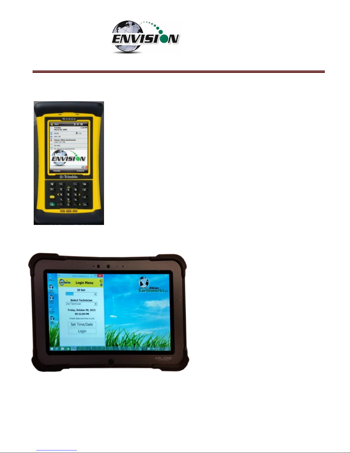
2.1.1 Trimble® Nomad ............................................................................................................................................................... 6
2.1.2 Xplore Bobcat ................................................................................................................................................................... 6
2.1.3 Juniper Archer 2 ............................................................................................................................................................... 7
2.1.4 Juniper Mesa 2 ................................................................................................................................................................. 7
2.1.5 Envision® Gas Analyzer .................................................................................................................................................... 8
3 SAFETY ................................................................................................................................................................................ 11
4 CERTIFICATION .................................................................................................................................................................... 11
5 TRIMBLE® HANDHELD COMPUTER PREPARATION .............................................................................................................. 12
5.1 TURNING ON THE TRIMBLE HANDHELD COMPUTER ........................................................................................................................ 12
5.2 TURNING OFF THE TRIMBLE HANDHELD COMPUTER ....................................................................................................................... 13
5.3 BACKLIGHT AND POWER SETTINGS .............................................................................................................................................. 13
5.4 ENABLE BLUETOOTH® .............................................................................................................................................................. 19
5.5 ENABLE GPS .......................................................................................................................................................................... 21
6 ENVISION® GAS ANALYZER APPLICATION ........................................................................................................................... 24
6.1 SOFTWARE SCREEN PROPERTIES ................................................................................................................................................. 25
6.2 “LOGIN SCREEN” - LOGGING TO THE ELKINS GAS ANALYZER SOFTWARE ............................................................................................. 26
6.3 CONNECTING AND DISCONNECTING THE ENVISION® GAS ANALYZER .................................................................................................. 30
6.3.1 Connecting to the Envision® Gas Analyzer ..................................................................................................................... 30
6.3.2 Bluetooth Connection ..................................................................................................................................................... 30
6.3.3 Serial Connection (if desired) .......................................................................................................................................... 34
6.3.4 Disconnecting from the Envision® .................................................................................................................................. 35
6.3.5 Resetting Bluetooth ........................................................................................................................................................ 37
6.4 MAIN MENU .......................................................................................................................................................................... 37
6.5 CALIBRATION .......................................................................................................................................................................... 37
6.5.1 Zero Gas Calibration ....................................................................................................................................................... 39
6.5.2 Span Gas Calibration ...................................................................................................................................................... 43
6.5.3 Pressure Sensor Calibration ............................................................................................................................................ 47
6.5.4 Storing a Calibration File ................................................................................................................................................ 52
6.6 ANALYZE ................................................................................................................................................................................ 55
6.6.1 Select ID .......................................................................................................................................................................... 55
6.6.2 Analyze ........................................................................................................................................................................... 65
6.6.3 Read Pressures (ENV100/200)........................................................................................................................................ 78
6.6.4 Read Pressures (ENVAUS) .............................................................................................................................................. 83
6.7 COMMENTS............................................................................................................................................................................ 88
6.8 VIEW AND STORE DATA ............................................................................................................................................................ 90
6.9 UTILITIES ............................................................................................................................................................................... 92
6.9.1 Well ID Maintenance ...................................................................................................................................................... 93
Page 3

P a g e | 3
6.9.2 View Missing Well Report ............................................................................................................................................ 114
6.9.3 Meter Status ................................................................................................................................................................. 116
6.9.4 License Manager .......................................................................................................................................................... 118
6.9.5 Set Options ................................................................................................................................................................... 120
6.9.6 Restore All Factory Cal ................................................................................................................................................. 122
6.10 STORED DATA ....................................................................................................................................................................... 123
6.11 O&M MANUAL .................................................................................................................................................................... 124
6.12 EXITING THE GAS ANALYZER SOFTWARE ..................................................................................................................................... 125
6.13 SOFTWARE OPTIONS .............................................................................................................................................................. 126
7 THE ENVISION® GAS ANALYZER CONFIGURATION EDITOR SOFTWARE ............................................................................. 128
7.1 LOADING THE APPLICATION ...................................................................................................................................................... 128
7.2 OPENING THE GAS ANALYZER CONFIGURATION EDITOR FOR THE FIRST TIME ..................................................................................... 128
7.3 ADD A SITE, TECHNICIAN, VALVE ADJUSTMENT, WELL CONDITION AND/OR WELL REPAIR ................................................................... 130
7.4 ADD A MONITORING POINT...................................................................................................................................................... 132
7.5 CLONING WELLS .................................................................................................................................................................... 137
7.6 DELETE WELLS ...................................................................................................................................................................... 140
7.7 COMBINING WELLS FROM ANOTHER ID SET................................................................................................................................. 142
7.8 SAVE FILE............................................................................................................................................................................. 144
7.9 ID SET STORED LOCATION ON PC .............................................................................................................................................. 145
7.10 TRANSFERRING ID SETS BETWEEN HANDHELD AND DESKTOP PC ..................................................................................................... 146
7.11 IMPORTING GEM CONFIGURATION FILES ................................................................................................................................... 150
7.12 PRINT PREVIEW ..................................................................................................................................................................... 151
8 CONNECTING THE HANDHELD COMPUTER TO A DESKTOP PC ........................................................................................... 152
8.1 WINDOWS MOBILE DEVICE CENTER .......................................................................................................................................... 152
8.2 WINDOWS XP MACHINES ....................................................................................................................................................... 156
8.2.1 Download Active sync .................................................................................................................................................. 156
8.3 TRANSFERRING FILES .............................................................................................................................................................. 162
8.3.1 Directory Structure ....................................................................................................................................................... 162
8.3.2 Copy Files from PC to Handheld Device ........................................................................................................................ 166
8.3.3 Copy File from Handheld Device to PC ......................................................................................................................... 169
9 ERRORS AND TROUBLESHOOTING .................................................................................................................................... 172
9.1 ENVISION
®
ERROR CONDITIONS: ............................................................................................................................................... 172
9.2 OTHER ERROR CODES ............................................................................................................................................................. 173
10 ENVISION® MAINTENANCE ................................................................................................................................................ 175
10.1 FACTORY MAINTENANCE ........................................................................................................................................................ 175
10.2 FIELD MAINTENANCE ............................................................................................................................................................. 175
11 WARRANTY ....................................................................................................................................................................... 177
11.1 ENVISION® WARRANTY .......................................................................................................................................................... 177
11.2 TRIMBLE HANDHELD WARRANTY .............................................................................................................................................. 177
Page 4

P a g e | 4
11.2.1 Hardware Warranty ................................................................................................................................................. 177
11.2.2 Hardware Warranty Exclusions ............................................................................................................................... 178
11.2.3 Software/Firmware Extended Limited Warranty ..................................................................................................... 178
11.2.4 Software/Firmware Warranty Exclusions ................................................................................................................ 178
12 PROBLEMS AND POTENTIAL SOLUTIONS FOR ENVISION AND HANDHELD DEVICE ............................................................ 179
13 SPECIFICATIONS ................................................................................................................................................................ 180
13.1 ENV100 & ENV200 SPECIFICATIONS ...................................................................................................................................... 180
13.2 ENVAUS SPECIFICATIONS ...................................................................................................................................................... 181
14 CONTACT INFORMATION – SERVICE AND SALES ............................................................................................................... 182
Page 5

P a g e | 5
1 Introduction
Elkins Earthworks® would like to welcome you to the Envision® gas analyzer system. The Envision® gas
analyzer, designed by Elkins Earthworks® is manufactured in the United States. The equipment was
designed for the field technician as well as project managers. The Envision® gas analyzer is a two-part
system, the sensor unit (Envision®) and the handheld computer. This unique pairing makes field
activities more productive by giving the user the ability to expand functionality by using GPS, barcoding, and other features that the Windows® operating system can offer.
There are currently 4 models of Envision gas analyzer:
ENV100 – has internal heating pads and is not certified intrinsically safe
ENV200 – does not have internal heating pads and is certified intrinsically safe
ENV200 “B” – same as ENV200 with added capability to measure barometric pressure
ENVAUS – does not have internal heating pads, is not certified intrinsically safe, and has borehole flow
measurement capability
2 The Envision® System
The Envision® gas meter is a unique field instrument utilized primarily for the measurement of CH4, CO2,
O2, pressure, temperature, and flow within landfill gas and bio-gas collection systems. The Envision®
gas analyzer package is comprised of two components: the handheld computer and the sensor unit
(Envision®).
2.1 Handheld Computer
Elkins Earthworks® currently offers 4 models of handheld computers that can run the Gas Analyzer
proprietary software to operate the Envision® sensor unit. The handheld computers typically
communicate with Envision® via Bluetooth® wireless technology.
Page 6
P a g e | 6
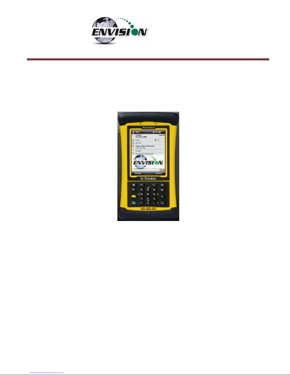
2.1.1 Trimble
®
Nomad
The Nomad is a highly ruggedized field computer from Trimble. The Trimble
series handhelds are all-in-one field computers for GIS (Geographic
Information System) data collection and mobile GIS applications, combining
a handheld computer powered by the Windows Mobile 6 or 6.1 operating
system. The Trimble series handhelds connect to the Envision® via
Bluetooth® or via serial cable. They come standard with Bluetooth and
802.11 (Wi-Fi). Optional features may also be selected such as GPS, barcode
scanner, and/or an internal camera.
2.1.2 Xplore Bobcat
Xplore’s Bobcat ruggedized tablet is IP65
rated, runs Windows 7, 8.1, or 10 and has a
bright 10” touch screen. It has a battery
life of 8 hours (standard) or 14 hours
(optional dual battery). Wi-Fi, GPS,
Bluetooth, and Ethernet communications
are standard with optional 4G LTE. The
Bobcat has a variety of pluggable ports,
cameras in the front and back and optional
barcode scanner, fingerprint scanner, and
near-field communication. It can survive
multiple drops at a height of 4 feet onto
plywood over concrete.
Page 7

P a g e | 7
2.1.3 Juniper Archer 2
The Archer 2 is an IP68 rugged handheld unit from Juniper Systems. It runs the
Windows Embedded Handheld 6.5.3 operating system (includes Windows Office
Mobile) and has a 4.3” high visibility touch screen. It can operate up to 20 hours
on a single charge.
2.1.4 Juniper Mesa 2
Juniper’s Mesa 2, 8.5” x 5.5”, IP68 ruggedized tablet comes with
the Windows 10 operating system and runs 8 – 10 hours on a
single charge. It has options for Bluetooth, Wi-Fi, 4G LTE, camera,
GPS, barcode scanner, RFID, and hot-swappable batteries.
Page 8
P a g e | 8
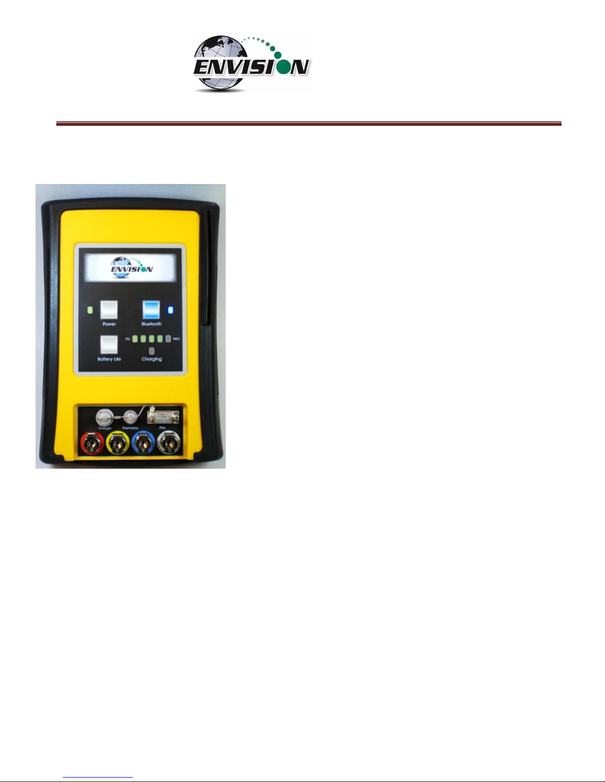
2.1.5 Envision® Gas Analyzer
The Envision® gas analyzer houses the gas and pressure
sensors. The gas analyzer utilizes infrared sensors to measure CH4
and CO2. The Envision® uses an electrochemical cell to measure O2
concentration and an accurate thermistor temperature probe to
measure wellhead gas temperatures. Data generated by the
Envision® gas analyzer is relayed to the handheld PC via Bluetooth
or serial cable several times per second.
Page 9
P a g e | 9
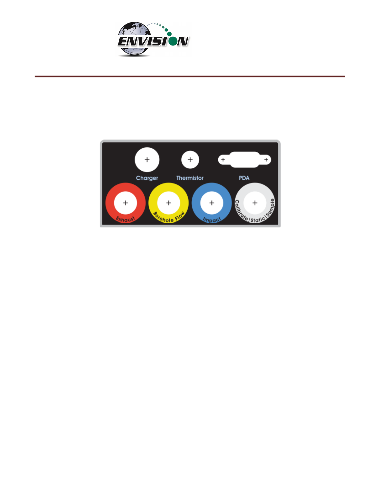
2.1.5.1 Gas Ports
The Envision® gas analyzer ENV100 and ENV200 models have four (4) ports located on the front of the
unit.
Figure 1 ENV100 and ENV200 Port Labels
Port listing from right to left:
Calibrate/Static/Sample port – This port is used to calibrate the unit with calibration gas, to measure
static wellhead pressure, and to sample for gas quality.
Impact Port – This port is used to generate a differential pressure for calculating flow. Do not connect
pressurized calibration gasses to this port.
Available – This port is used to acquire an available (system) vacuum at the monitoring port. Do not
connect pressurized calibration gasses to this port.
Exhaust – This port is used to exhaust the gasses that are pumped through the sample train for
measurement. Only connect an exhaust hose to this port. Do not apply pressure to the exhaust port.
Page 10
P a g e | 10
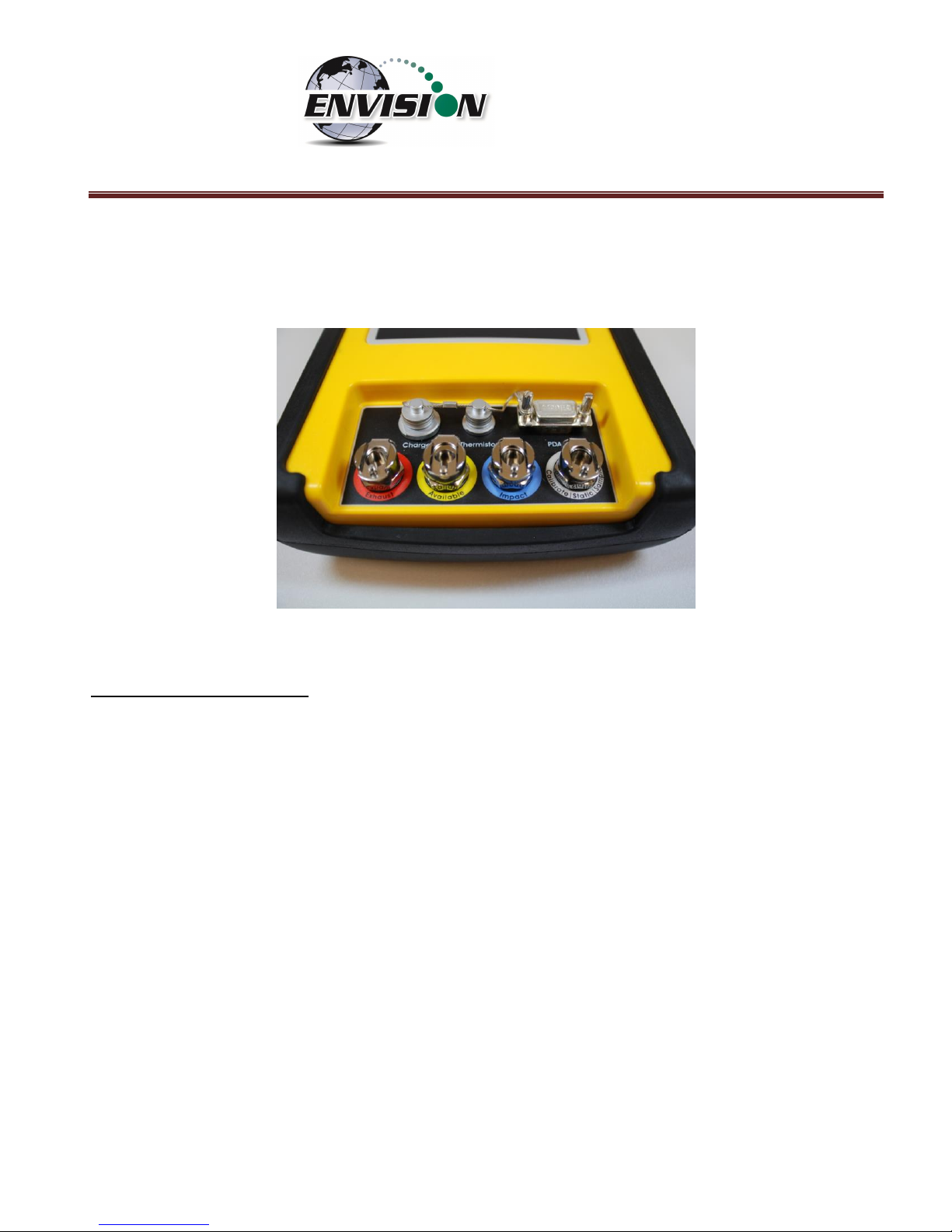
The Envision® gas analyzer ENVAUS model is slightly different in that the yellow “Available” port is now
labeled “Borehole Flow” (see photo below). Instead of measuring available (system) vacuum at this
port, it is used to measure low-level borehole flow instead. The “Calibrate/Static/Sample” port is then
used to measure available (system) vacuum.
Figure 2 ENVAUS Port Labels
2.1.5.2 Cable Ports
Charger port – This port is used to charge the unit with the supplied wall charger. The Envision should
run a full, normal working day without needing to be recharged. Plug the charger in overnight to charge
the unit. It usually takes about 4 hours to fully charge an Envision. The charging circuit will turn off
automatically when the unit has reached a full charge. Do not plug the charger into the unit in an
explosive environment.
Thermistor Port – The wired thermistor plugs in to this port. If you have purchased a wireless
(Bluetooth) thermometer from Elkins Earthworks, it may be used in place of the wired thermistor.
PDA Port – The PDA port may be used to directly connect the Envision to a handheld device (with a
serial port) if Bluetooth is unavailable or not working correctly. A standard 9 pin serial cable may be
used.
Page 11

P a g e | 11
3 Safety
Landfill gas is normally safely extracted from landfills and conveyed to appropriate control
devices. However, during the course of monitoring each extraction point, exposure may occur. As such,
it is important to follow all site-specific safety protocols when monitoring. Working at a landfill typically
requires site specific health and safety plans. While performing monitoring at a landfill, the user should
be aware of the items included in the site specific health and safety plan. It is important to know that
all personal protection equipment and safety protocols as appropriate must be used when using this
instrument. All vents on the meter are designed to exhaust to the atmosphere. Since landfill gas
contains methane, no smoking is permitted while using the instrument. Calibration gases must be
handled with utmost care and with adequate ventilation.
It is the sole responsibility of the user of the Envision® sensor unit and handheld PC to determine the
appropriate location that either unit can be utilized within as monitoring conditions may change. The
Envision® sensor unit handheld PC are not intended for use in confined space entries but for the
continuous monitoring of gasses within a landfill gas collection system.
4 Certification
Envision® model ENV200 has been UL certified for use in
hazardous locations (Class 1, Zone 1, AEx d ib IIA T4) when
connected in accordance with control drawing 1104M200.
Although models ENV100 and ENVAUS are based on a similar
design, these models have not been certified for use in explosive
atmospheres. It is important that this manual be followed closely
and that any repair to the Envision® gas analyzer is made at the
approved Elkins Earthworks® repair facility. Opening the Envision® gas analyzer and breaking the
housing warranty seals may result in voiding the unit’s warranty as well as compromising the unit’s
safety. The charger should not be connected when an explosive atmosphere is present.
The Envision® sensor unit also meets FCC regulations for a Class A Digital Device Part 15, Subpart B,
Sections 15.107b & 15.109b
Page 12
P a g e | 12
5 Trimble® Handheld Computer Preparation
Note: The Trimble Nomad has traditionally been the default handheld PC used with the Envision gas
analyzer. Although other handheld units have been recently introduced, this section of the manual has
been retained for reference.
The Trimble handheld computer is the prime driver for the Envision® gas analyzer. The Trimble
handheld computer, provided with the Envision® gas analyzer package, has already been prepared for
field use. A screen protector has already been applied to your Trimble unit. An extra screen protector
has been included in the packaging.
The operational software for the Envision® Gas Analyzer has been installed at the factory. The Trimble
handheld computers operate on the Microsoft Mobile 6.0, 6.1, or 6.5 operating systems. The features
on the Trimble are similar to those on the standard Microsoft XP and Vista operating systems found on
many desktops and laptops. For general information on the features of the Trimble Nomad and
Windows Mobile 6.0, 6.1, or 6.5 please refer to the supplemental information provided in the packaging
of the Envision® Gas Analyzer.
5.1 Turning on the Trimble Handheld Computer
To turn on the Trimble handheld computer, the user must press the green power button located at the
lower left side of the Trimble keypad.
Page 13

P a g e | 13
5.2 Turning off the Trimble Handheld Computer
1) Press the green power button for two seconds
2) Tap the shutdown button on the touch screen
3) Tap yes on the popup screen if you agree with the warning message
5.3 Backlight and Power Settings
Elkins Earthworks® has already adjusted your Trimble handheld computer for the following backlight
and power settings:
Parameter
Battery Power
External Power
Backlight*
Never turns off
Never turns off
Backlight Brightness
100%
100%
Keypad on Time
1 minute
1 minute
Keypad Brightness
100%
100%
Hibernation**
Never
Never
* If the user changes the backlight setting the Envision® will lose Bluetooth connection when the unit
enters and recovers from the backlight being powered on and off. The unit will regain Bluetooth
connection almost instantly.
** Hibernation mode will cause the Envision® to lose connection and will need to be reconnected once
the Nomad is turned back on. Elkins Earthworks® recommends that these settings remain as set upon
delivery.
Page 14

P a g e | 14
Changing Backlight Settings
If the user would like to change these settings, then follow the steps below:
1) Turn on the Trimble handheld computer by pressing the green power button on the handheld
computer keypad.
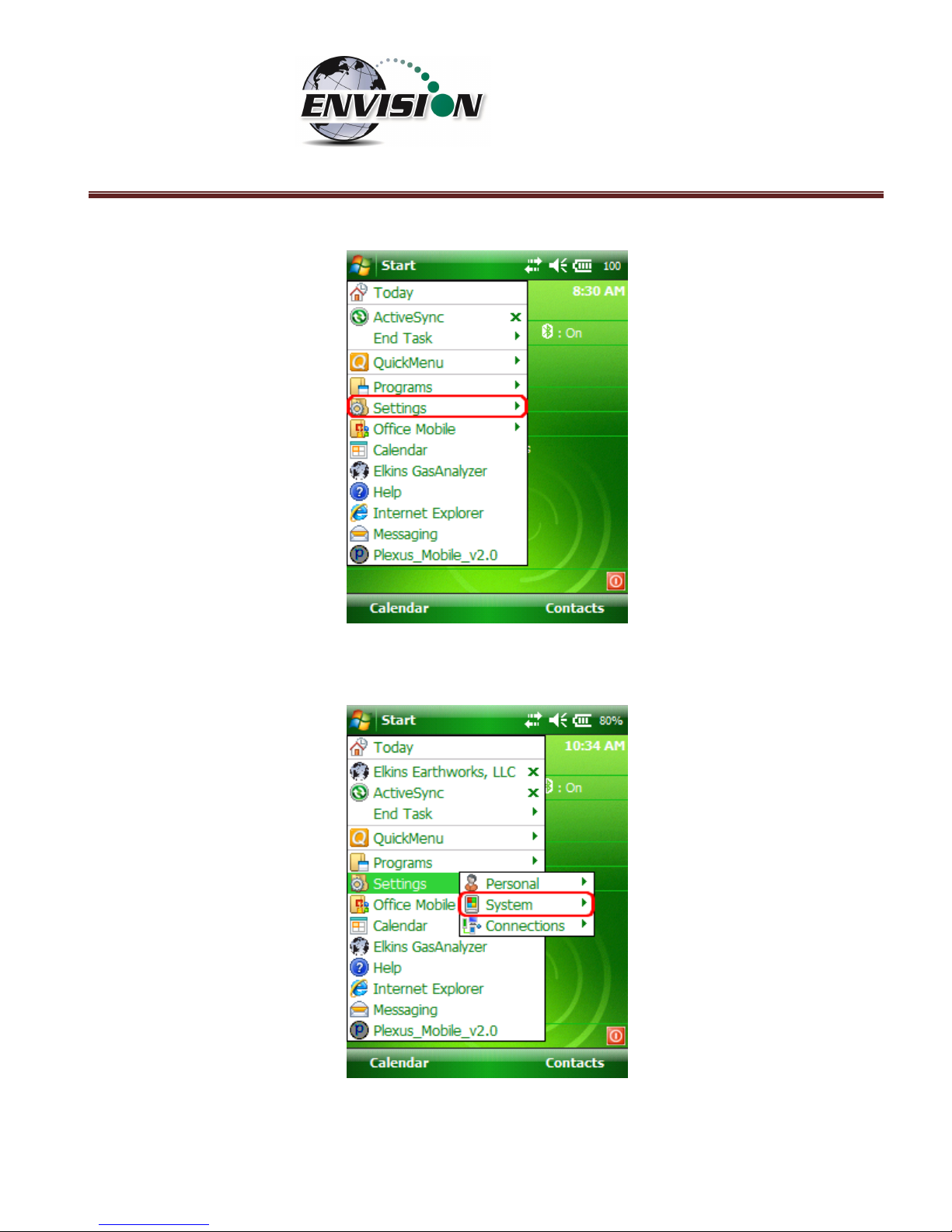
2) On the touch screen tap the “Start” button in the upper left hand corner of the touch screen
Page 15
P a g e | 15
3) Tap “Settings”
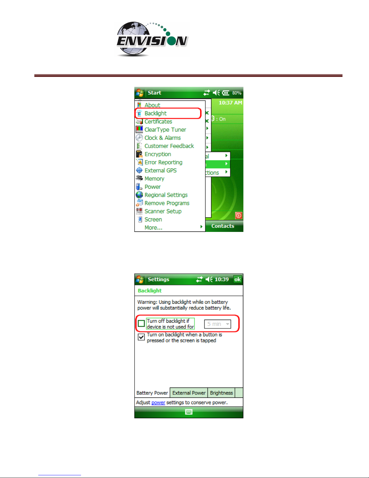
4) Next tap “System”
5) Next tap “Backlight”
Page 16
P a g e | 16
6) On the “Battery Power” and “External Power” screens, uncheck the “Turn off backlight if device is
not used for” box.
Page 17
P a g e | 17
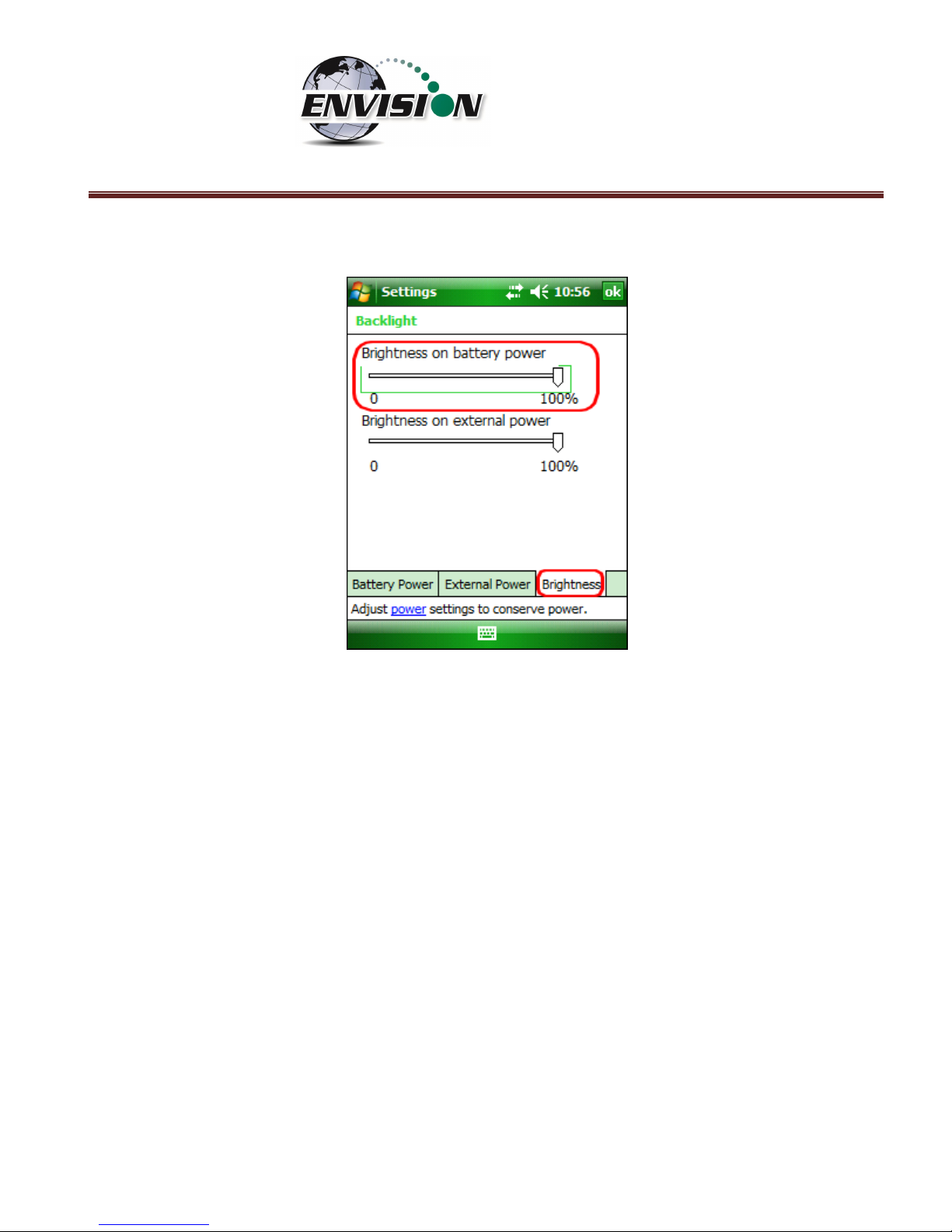
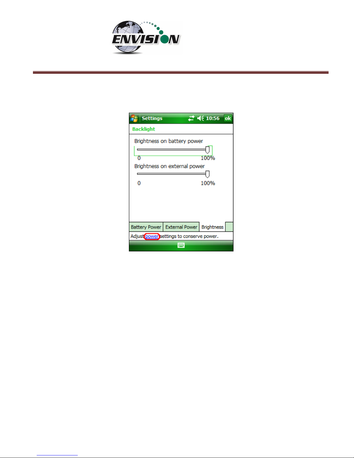
7) Tap on the Brightness tab at the bottom of the screen.
8) Increase the brightness to 100%
Page 18
P a g e | 18
9) At the bottom of the “Brightness” screen select “Power” in the adjust power setting to conserve
power.
Page 19
P a g e | 19
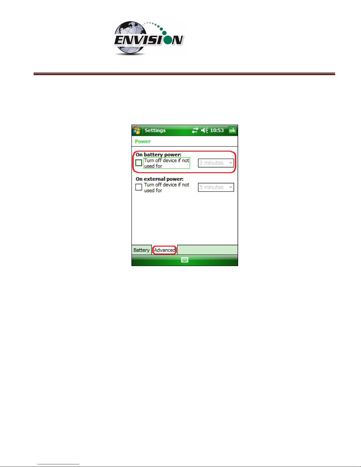
10) Select the “Advanced” tab then uncheck the box “Turn off device if not used for”. This will keep
the unit from going into hibernation. If the Trimble handheld computer goes into hibernation it
will lose connection with the Envision® gas analyzer.
11) Exit by tapping the “OK” button twice.
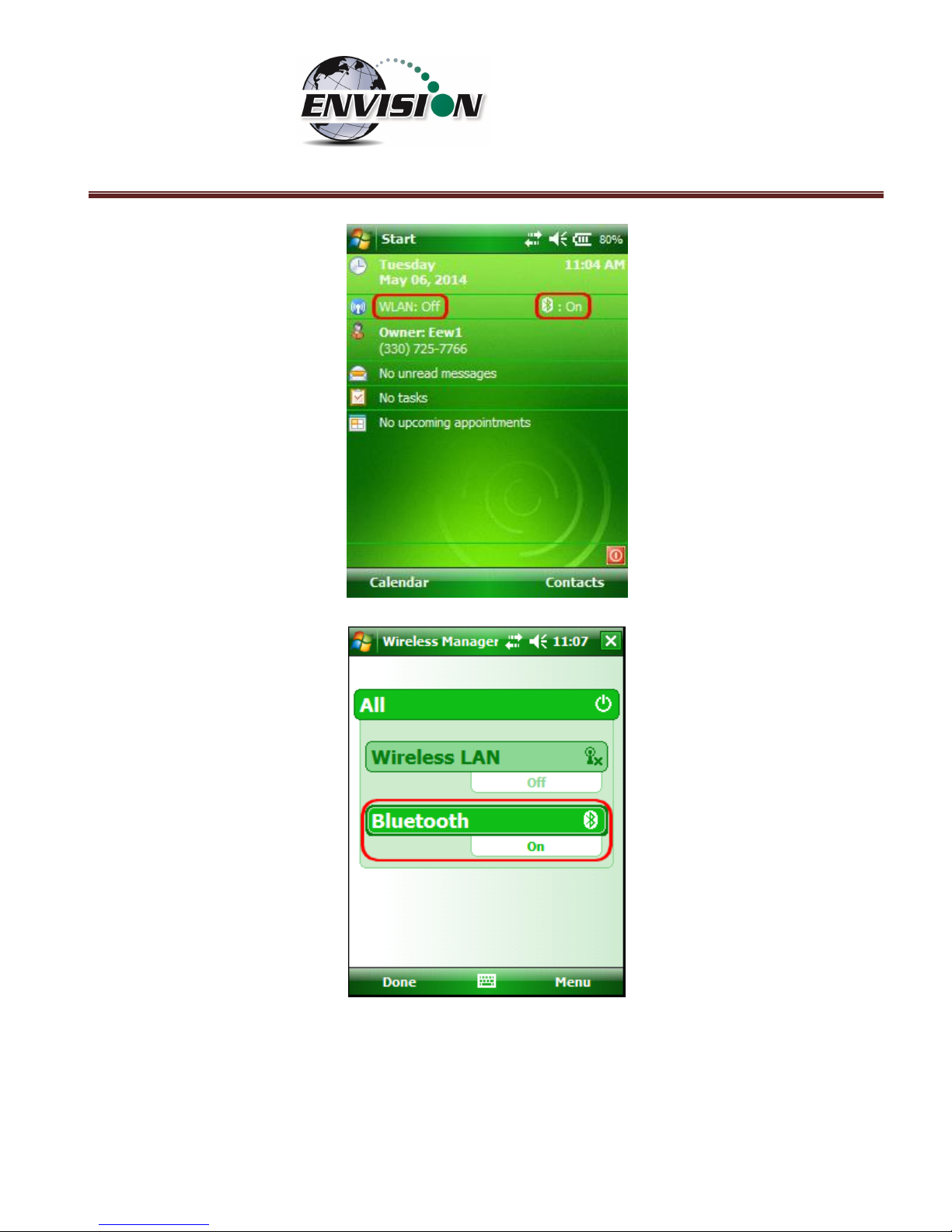
5.4 Enable Bluetooth®
The primary way to connect with the Envision® gas analyzer is via Bluetooth® connection. The unit
ships from the factory with Bluetooth enabled. The gas analyzer software will also enable Bluetooth.
However, if Bluetooth becomes disabled, tap the Bluetooth icon on the Main Windows Screen. Also,
the gas analyzer software may automatically turn the WLAN (wireless network) off to prevent it from
interfering with the Bluetooth connection.
Page 20
P a g e | 20
Next, on the Wireless Manager Screen tap the Bluetooth button and Bluetooth will activate.
Page 21
P a g e | 21
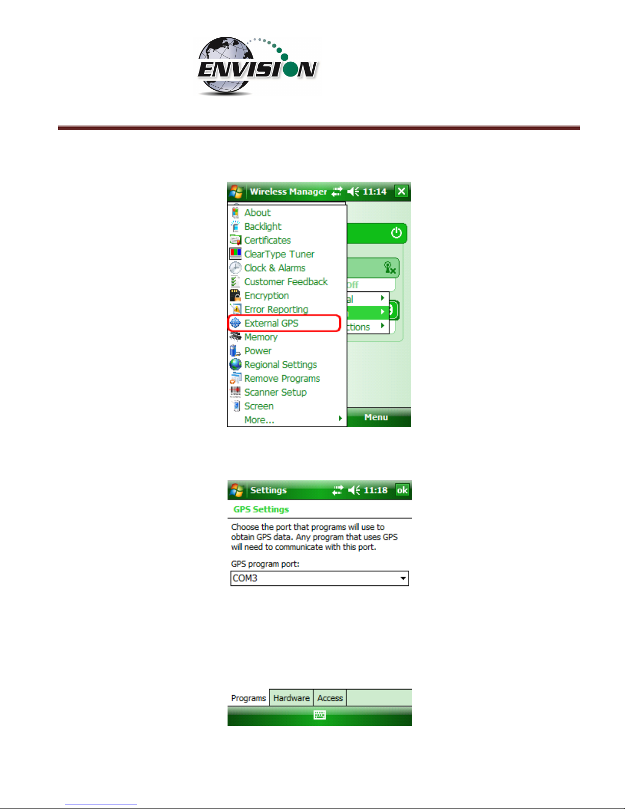
5.5 Enable GPS
The Envision® gas analyzer system software is designed to utilize GPS to locate monitoring points. Units
that are purchased with the GPS option require no setup to enable the GPS feature. The software
developed for the Envision® gas analyzer automatically turns the GPS on and off when needed. Do not
change any of the GPS settings in the Trimble handheld computer. The Trimble handheld computer has
been shipped with default settings. If the GPS fails to connect the user should check the GPS in the
following manner:
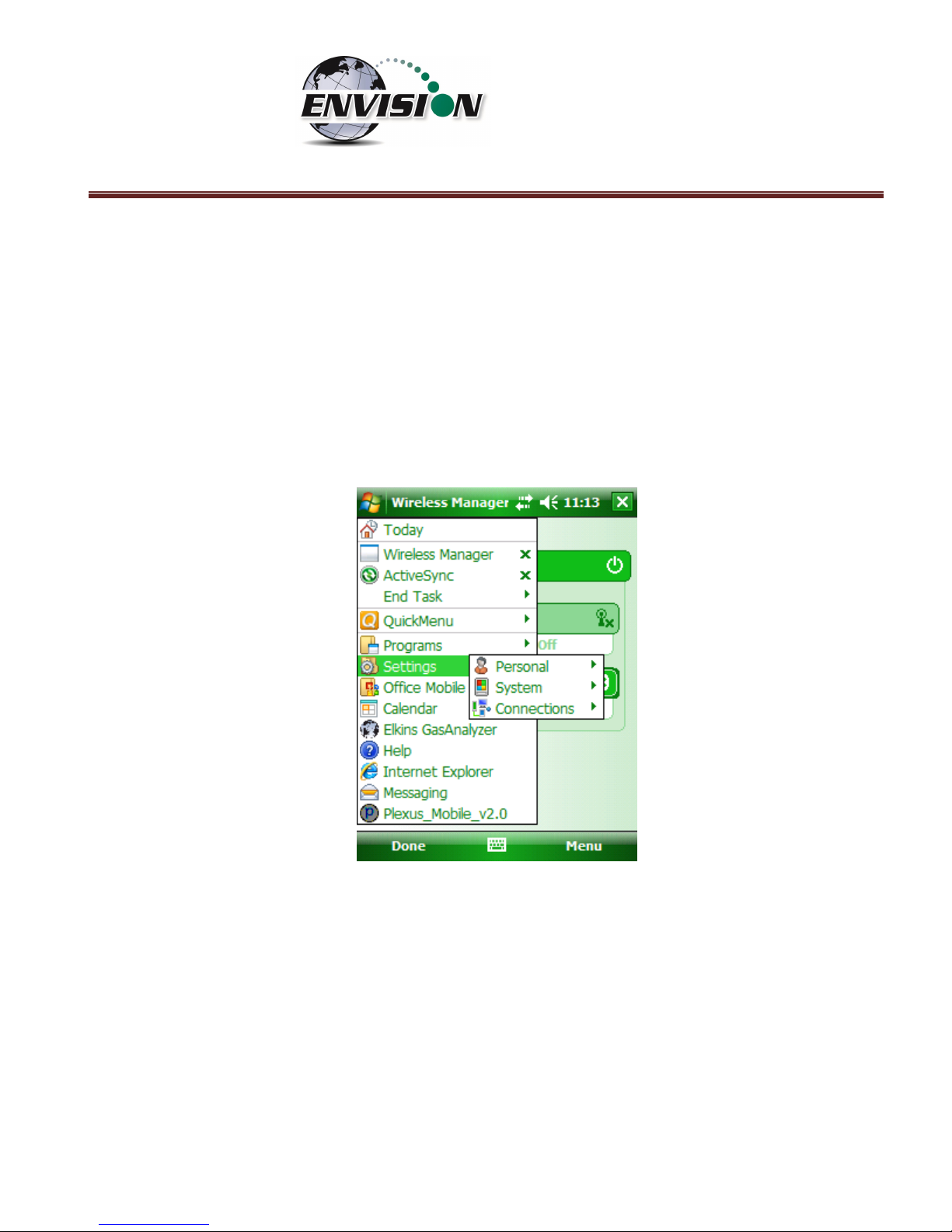
1) Tap the “Start” button in the upper left corner of the screen and tap settings
Page 22
P a g e | 22
2) Tap System and then External GPS
3) Verify GPS program port is set to COM 3
Page 23
P a g e | 23
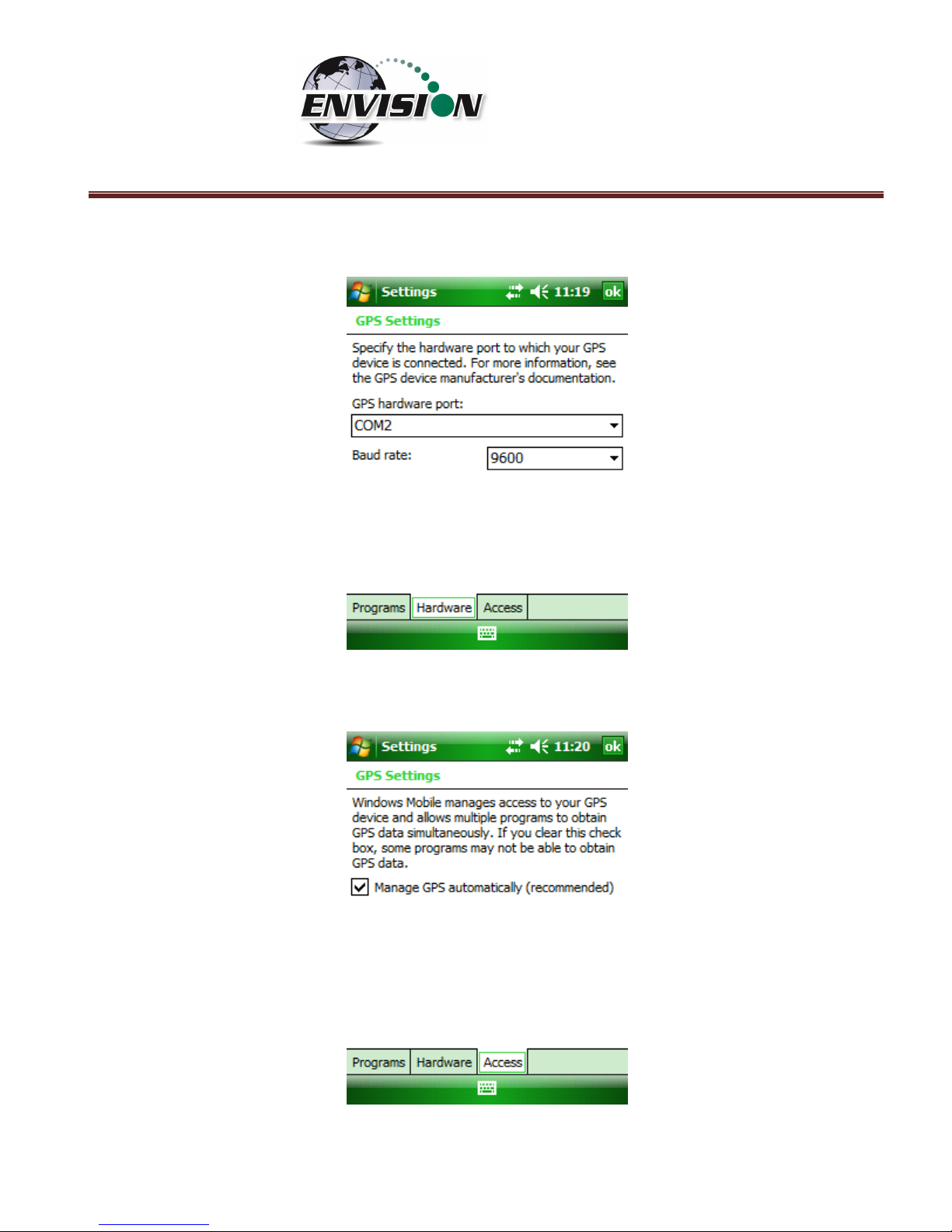
4) GPS Hardware Port is set to COM2 and BAUD rate 9600
5) Verify that this box is checked too.
Page 24
P a g e | 24
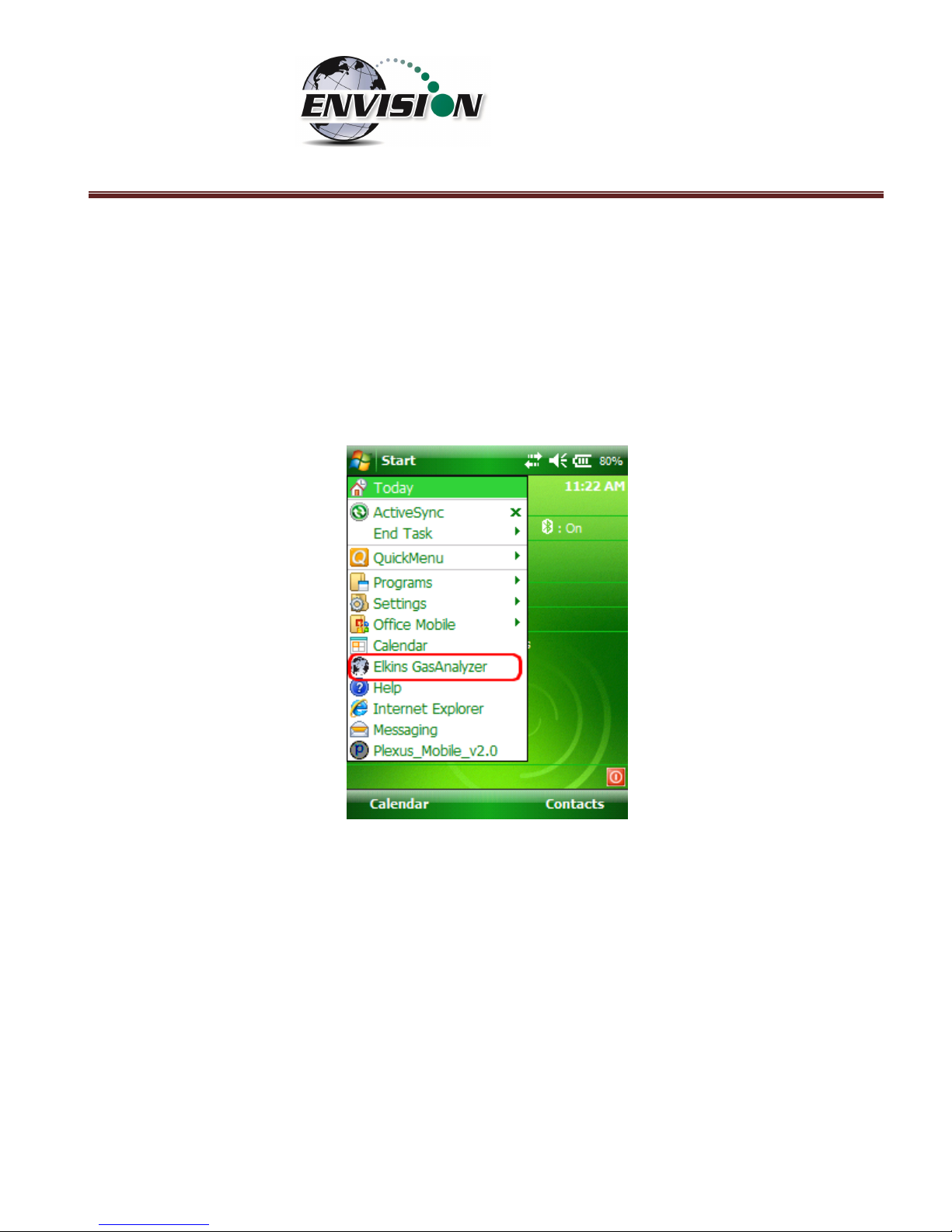
6 Envision® Gas Analyzer Application
The “Elkins Gas Analyzer” program is the software developed to run the Envision® gas analyzer. To
activate the Gas Analyzer program, follow the steps below:
1) Click Start in the upper left hand corner of the screen and tap the “Elkins Gas Analyzer” button in
the drop down menu. Note: If the Gas Analyzer is not listed in the main menu, click on
“Programs”. It should be listed there.
2) The application will start and the “Login Menu” will appear
3) If the “Elkins Gas Analyzer” program is already running, then the application will open to the last
screen that the user was viewing.
Page 25
P a g e | 25
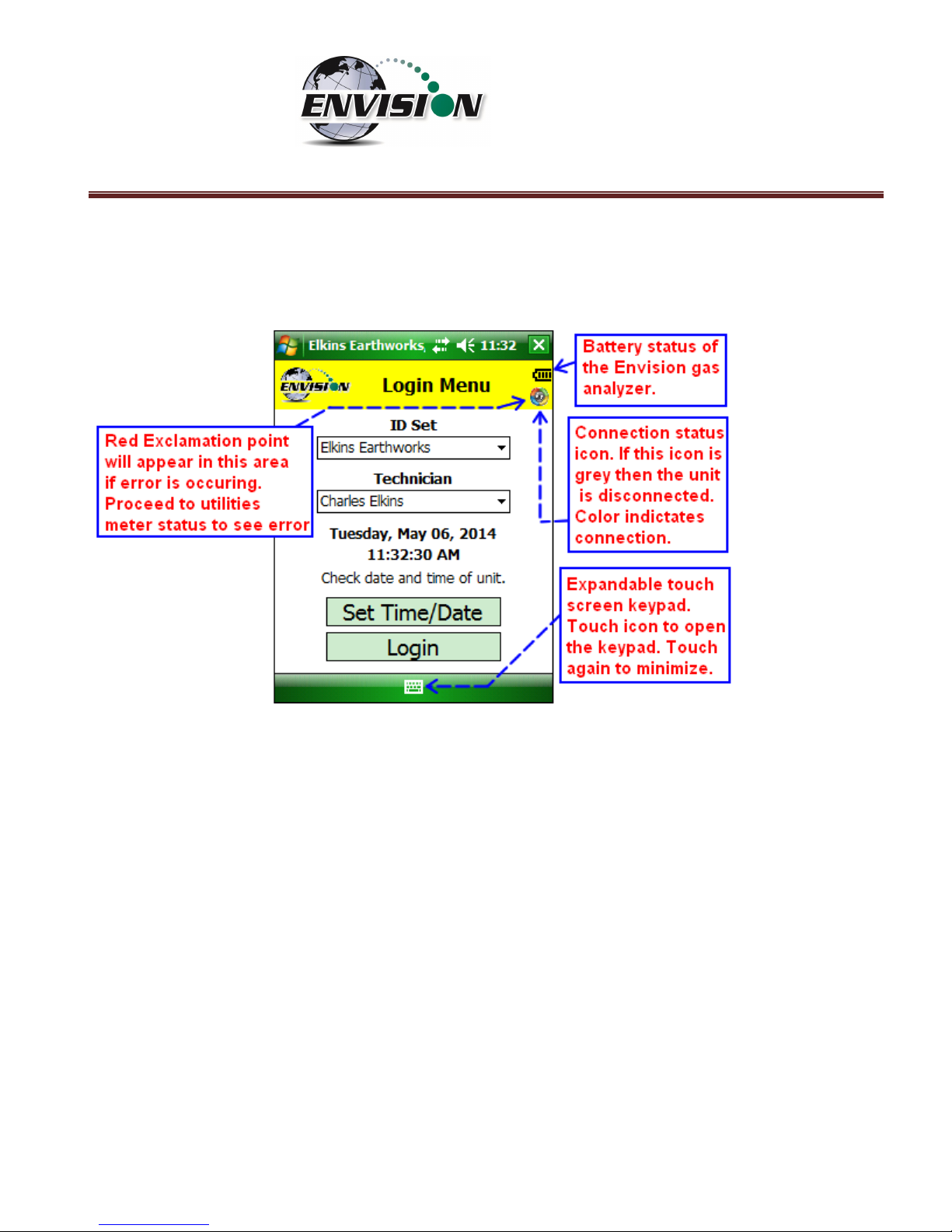
6.1 Software Screen Properties
The detail below illustrates the main features common to each screen of the Elkins Gas Analyzer
Program.
Page 26
P a g e | 26
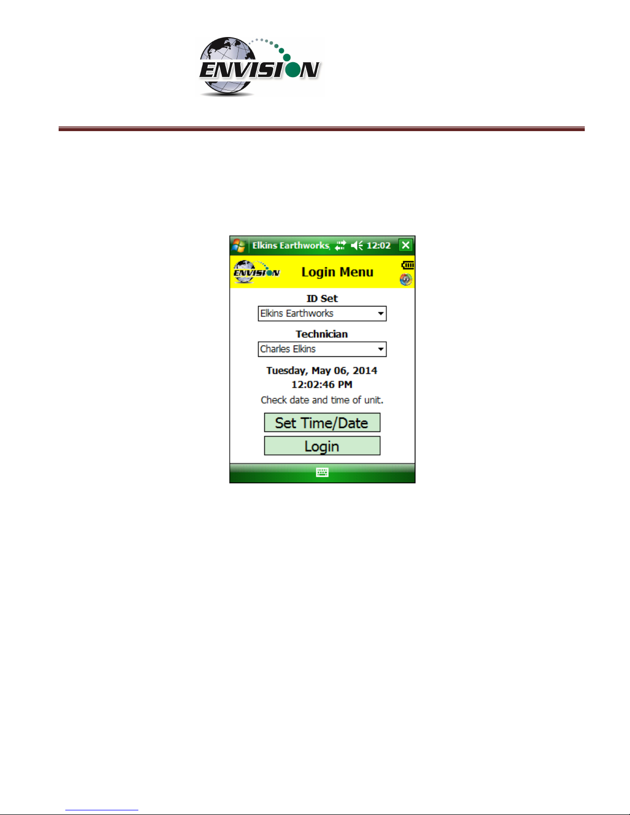
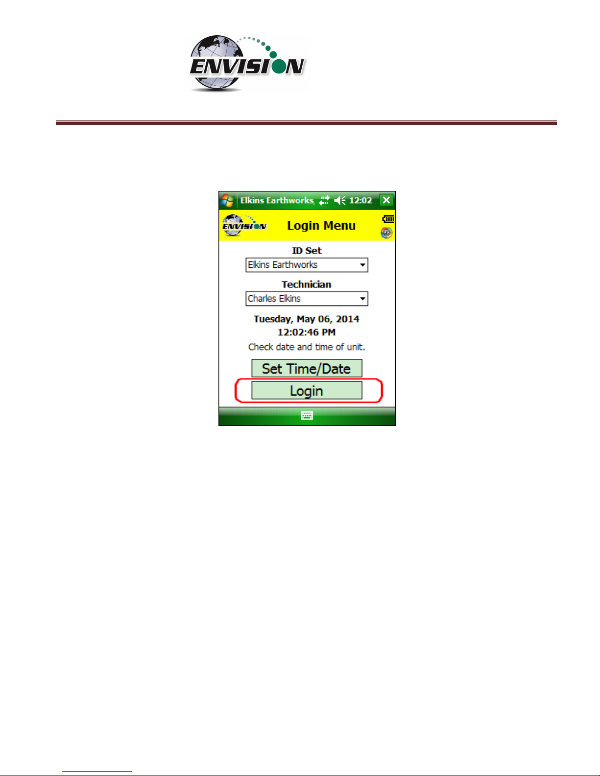
6.2 “Login Screen” - Logging to the Elkins Gas Analyzer Software
Once the Elkins Gas Analyzer program is started from the “Start Menu” the “Login Menu” will appear.
This screen is intended to allow the user to login to the Elkins Gas Analyzer program.
Page 27
P a g e | 27
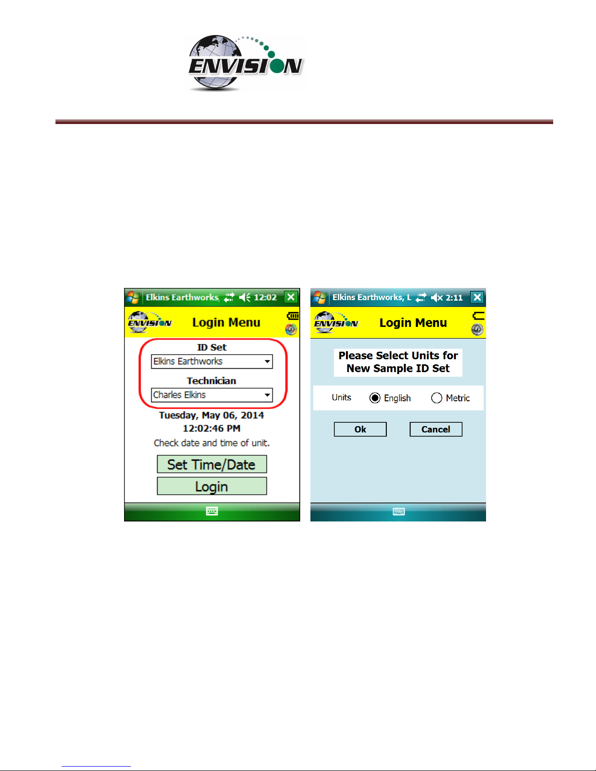
1) Select the Desired ID set and the name of the Technician who will be using the Envision® gas
analyzer from the drop down menu located at the center of the “Login Menu” screen. ID sets
may be added to this drop down menu by utilizing the “Elkins Earthworks® Configuration Editor”
software that may be installed on your personal computer. The “Elkins Earthworks®
Configuration Editor” software is provided on the Elkins Earthworks® software Flash drive
included in the original packaging of the Envision® gas analyzer. Both ID sets and technician
names may also be added directly from the drop down list on the Login Menu. When adding a
new ID set, the user may be prompted to choose either English or Metric units of measurement.
Page 28
P a g e | 28
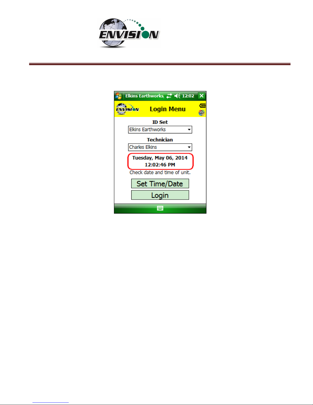
2) Verify that the date and time is correct as displayed on the login screen
3) If date and/or time is incorrect then tap the “Set Time/Date” button
Page 29
P a g e | 29
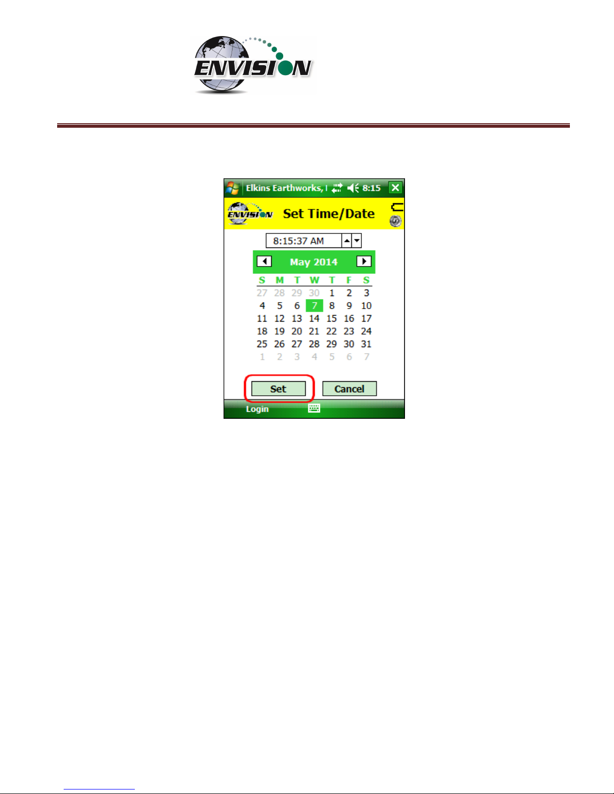
4) The “Set Time/Date” screen will appear and you may then adjust to the correct date and/or time
5) Tap the “Set” button when the date and time have been corrected. This will return the user to
the Login Screen.
Page 30
P a g e | 30
6) If the user name and time are now correct, then tap the “Login” button at the bottom of the
screen.
6.3 Connecting and Disconnecting the Envision® Gas Analyzer
6.3.1 Connecting to the Envision® Gas Analyzer
The user can connect to the Envision® gas analyzer in one of two ways, by Bluetooth or serial
connection.
6.3.2 Bluetooth Connection
Once the user is logged in, the user can now search for and connect to an Envision® gas analyzer.
1) On the handheld computer make sure that the “Select Meter” screen is displayed
2) Turn on the Envision® gas analyzer by pressing the power button on the front of the Envision® gas
analyzer
3) The Envision® gas analyzer will maintain a solid green light next to the power button
4) Next press the Bluetooth® button on the face of the Envision® gas analyzer. The blue light on the
Envision® gas analyzer will blink now that it is discoverable and can allow the handheld computer
to find it.
Page 31

P a g e | 31
5) The user should now tap the “Search” button on the “Select meter” screen on the handheld
computer.
6) The handheld computer screen will display “Searching…” above the “Meters” box and will change
to “Select Meter to connect” once the Envision® gas analyzer is discovered.
Page 32

P a g e | 32
7) The Envision® gas analyzer should be displayed in the box titled “Devices”. Each discoverable
Envision® unit should appear and will be defined by the name Elkins Envision® followed by the
unit’s serial number.
Page 33

P a g e | 33
8) Select the desired analyzer by tapping the Envision® Meter ID and then tapping “Connect”. If you
are using a Bluetherm® temperature probe, you may also select it and connect to it at this time.
Page 34

P a g e | 34
9) Once the connection is made the words “Connected to ….” will be displayed in green above the
“Meters” screen. The blinking blue light on the Envision® gas analyzer will stop blinking and will
now show solid blue. The connection symbol in the yellow header box on the Trimble handheld
computer screen will now be multicolored indicating a connection with the Envision® gas
analyzer. The battery strength indicator located in the yellow header box will now display the
approximate battery level of the Envision® gas analyzer.
10) Once connected, tap the “Main Menu” button on the lower right hand corner of the screen.
6.3.3 Serial Connection (if desired)
If the user has problems with the Bluetooth link or desires to make a direct wired connection to the
Envision® gas analyzer, the user may use a standard RS232 Serial cable connection. This connection
requires an RS232 port on the handheld computer.
1) Tap “Login” on the “Login Menu”
2) Connect the handheld computer to the Envision® gas analyzer with the RS232 serial cable
3) Select “Serial Connection” in the analyzer display area.
Page 35

P a g e | 35
4) Tap the button connect and the word “Connected to ….”” will be displayed above the
“Meters” screen.
5) Once connected tap the “Main Menu” button on the lower right hand corner of the screen.
6.3.4 Disconnecting from the Envision®
To disconnect from the Envision® gas analyzer follow the steps listed below:
1) From the “Main Menu” tap the “Select Meter” button on the lower left corner of the touch screen.
Page 36

P a g e | 36
2) Tap the “Disconnect” button
Page 37

P a g e | 37
6.3.5 Resetting Bluetooth
If the connection to the Envision happens to drop, it may be necessary to reset Bluetooth in order to
reconnect. After Bluetooth resets, it is necessary to search again to find the Envision.
6.4 Main Menu
The “Main Menu” is the user’s access point for all of the features included in the Elkins Gas Analyzer
software. On this screen the user may select any one of the functions indicated on the buttons or the
user may return to the “Select Meter” screen by tapping the “Select Meter” button in the lower left
corner of the touch screen. The following sections will walk the user through each of the functions
indicated on the “Main Menu” screen.
6.5 Calibration
The Envision® gas analyzer has three internal gas measurement sensors (CH4, CO2 and O2) and five
pressure sensors that have been calibrated in the factory. The factory calibration results are stored
within the Envision® gas analyzer and can only be altered in the factory. The Envision® gas analyzer
should be field calibrated prior to each monitoring event. The field calibration file is stored within the
handheld computer.
Page 38

P a g e | 38
To enter the calibration area of the software, tap the “Calibrate” button on the “Main Menu” screen.
The calibration process of the Envision® gas analyzer was built to be simple for the field user. Follow
the calibration procedure described below to accurately calibrate the Envision® gas analyzer.
Each gas sensor should be calibrated with a zero gas and a span gas. The technician may calibrate
sensors in any order. However, for greatest accuracy, CO2 span should be calibrated before CH4 span
(minimizes cross-sensitivity). It is also recommended that when one gas sensor is calibrated that all
sensors should be calibrated for zero and span.
The calibration menu is shown below. The CSV (comma separated variable) file containing the last
calibration information is stored on the handheld PC. This file may be opened in any text editor (or
Microsoft Excel).
Page 39

P a g e | 39
6.5.1 Zero Gas Calibration
The typical order of calibration is to do zero gas first, followed by span gas.
1) Tap the “Zero” button of the gas that is to be calibrated. This action will take the
software to the “Calibration … Zero” screen
2) The user now has the ability to scan the barcode on the calibration cylinder. Tap the
“Scan Barcode” button and aim the scanner laser at the barcode on the calibration gas
cylinder being utilized. The barcode number will automatically populate the “Calibration
Gas Cylinder #” text box. The user can manually type in the bottle lot# using the numeric
keypad on the Trimble or the user may proceed without entering a cylinder number. This
data will be recorded in the calibration .csv file that is stored during the calibration
process.
Page 40

P a g e | 40
3) Attach the calibration gas to the Static sample port located on the front of the Envision®
gas analyzer and open the regulator valve. Elkins Earthworks® strongly recommends the
use of a Demand Flow regulator. Warning – If using a tunable regulator, use a setting of
.5 LPM and attach the calibration gas only to the Static port. Do not attach the calibration
gas to the Exhaust, Impact or Available ports. Pressures above 200” H20 on any port may
result in a damaged pressure sensor.
4) Tap the “Start Calibration” button. This action will turn on the sample pump and will
change the handheld computer display.
5) The following image shows the zero calibration screen. The “Calibration Value” located in
the middle should be 0.0%.
6) When the “Current Value” is less than 1% the Calibration status will display “Press
calibrate when measurement stabilizes”. This does not mean that the sensor has fully
stabilized but that the unit is within the 1% tolerance allowed when zeroing. Tap the
“Calibrate” button once the current value has stabilized. If this button is pressed before
the measurement is fully stabilized, the calibration will be inaccurate and, in some cases,
make the Envision unable to pass a span calibration. If the measurement continues to fall
Page 41

P a g e | 41
after the button is pressed, it is ok to press the calibrate button a second (or third) time to
get a better zero.
a. If the “Current Value” is between 0% and 1% then the handheld computer will adjust
and store your calibration once the user taps the “calibrate” button.
b. If the “Current Value” is greater than 1% then the handheld computer will display the
following message “Current measurement is outside of expected range. Please verify
calibration gas value and/or restore factory calibration.” The technician may discard
the field calibration value and restore the factory calibration value by tapping the
“Restore Factory Calibration” button on the “Calibration … Zero” screen. The
technician should then try to recalibrate. If the unit will not calibrate then the user
should contact technical support at Elkins Earthworks® at 330-725-7766.
7) The pump will continue to run and the sensors will continue to monitor until the user
returns to the “Calibration” menu by tapping the “Calibration” button in the lower right
hand corner of the touch screen.
8) Now that the Trimble handheld computer has returned to the “Calibration Menu” the
user will notice that the parameter that has been calibrated is now highlighted in green.
The user may now select the next gas to calibrate.
Page 42

P a g e | 42
Page 43

P a g e | 43
6.5.2 Span Gas Calibration
1) On the “Calibration Menu” tap the “Span” button of the gas that is to be calibrated. This
will take the user to the “Calibration … Span” screen.
2) On this screen there are two preset calibration gas values and one text box that the user
can type in a user defined calibration gas value using the touch screen keyboard or
numeric keypad. If selecting a user defined gas quality, the user must enter a value 0.1%
to 100%.
3) If the user types in a span gas value, he must first type in the desired gas quality then tap
the “User Defined” button. Once the user taps “User Defined” or either one of the two
predetermined gas qualities, the screen will then change to the “Calibration … Span”
screen.
4) The user now has the ability to scan the barcode on the calibration cylinder. Tap the
“Scan Barcode” button and aim the scanner laser at the barcode on the calibration gas
cylinder being utilized. The label number will automatically populate the “Calibration Gas
Cylinder #” text box. The user can manually type in the bottle lot# using the numeric
keypad on the Trimble or the user may proceed without entering cylinder #. This data will
be recorded in the calibration .csv file that is stored at the end of the calibration process.
Page 44

P a g e | 44
5) Attach the calibration gas to the Static sample port located on the front of the Envision®
gas analyzer and open the regulator valve. Elkins Earthworks® strongly recommends the
use of a Demand Flow regulator. Warning – If using a tunable regulator, use a setting of
.5 LPM and attach the calibration gas only to the Static port. Do not attach the calibration
gas to the Exhaust, Impact or Available ports. Pressures above 200” H20 on any port may
result in a damaged pressure sensor.
6) Tap the “Start Calibration” button. This action will turn on the sample pump and will
change the display. The “Calibration Value” located in the middle of the touch screen
should be the same as the gas quality that is being used for calibration and will not
fluctuate.
Page 45

P a g e | 45
7) Once the sensors are initiated and warmed up the “Current Value” will fluctuate. When
the “Current Value” is between 0% and 20% (relative) of the calibration gas value the
Calibration status will display “Press calibrate when measurement stabilizes”. Tap the
“Calibrate” button once the current value has stabilized. If this button is pressed before
the measurement is fully stabilized, the calibration will be inaccurate. If the measurement
continues to change after the button is pressed, it is ok to press the calibrate button a
second (or third) time to get a better span.
a. If the “Current Value” is between 0% and 20% (relative) of the calibration gas
value, then the handheld computer will adjust and store the calibration value once
the user taps the “calibrate” button.
b. If the “Current Value” is greater than 20% (relative) of the calibration gas value,
then the handheld computer will display the following message “Current
measurement is outside of expected range. Please verify calibration gas value
and/or restore factory calibration.” The technician may discard the field
calibration value and restore the factory calibration value by tapping the “Restore
Factory Calibration” button on the “Calibration … Span” screen. The technician
should then try to recalibrate. If the unit will not calibrate then the user should
contact technical support at Elkins Earthworks® at 330-725-7766.
Page 46

P a g e | 46
8) Now that the handheld computer has returned to the “Calibration Menu” the user will
notice that the parameter that has been calibrated is now highlighted in green. The user
may now select the next gas to calibrate.
Page 47

P a g e | 47
6.5.3 Pressure Sensor Calibration
The Envision® gas analyzer has 5 internal pressure sensors. These sensors should be field calibrated at
the beginning and periodically during the monitoring event. The pressure sensors may be zeroed from
two different locations in the Elkins Earthworks® Analyzer software.
From the “Calibration Menu”
1) Tap the “Pressure Zero” button. The screen will change to the “Pressure Calibration”
screen.
Page 48

P a g e | 48
2) On the “Pressure Calibration” screen allow the pressures in the 5 pressure blocks to
stabilize. The ENV100/200 screen is shown to the left and ENVAUS screen is shown to the
right below.
The Envision ENV200 “B” models have the added capability to measure barometric pressure. This
measurement is shown on the screen below.
Page 49

P a g e | 49
3) Ensure that the sample fittings are disconnected from the wellhead and shielded from
wind
4) Tap the “Zero Sensors” button on the lower center part of the touch screen.
Page 50

P a g e | 50
5) The values in the green pressure boxes should now read close to 0.00” H2O. Due to the
high sensitivity of the sensors the values may still fluctuate but they should be close to the
target value.
6) The user may also restore the factory calibration by tapping the “Restore Factory
Calibration” button.
7) Tap the “Calibration” button on the lower right of the screen to return to the main
“Calibration” screen. The pressure sensor calibration menu is also accessible from the
pressure measurement screen in the analyze portion of the software. On the read
“Pressures” screen tap the “Calibrate Sensors” button. This action will take you to the
pressure sensor calibration screen that was just described in the previous section.
Page 51

P a g e | 51
Follow the same pressure calibration procedure as detailed in the previous section then tap the Analyze
button in the lower right corner of the screen.
Warning: Never apply vacuums greater than -200” H20 or pressure greater than +200” H2O to any of the
pressure sensors during calibration or measurement activities. These extreme pressures can damage
the pressure sensors within the Envision® gas analyzer.
Page 52

P a g e | 52
6.5.4 Storing a Calibration File
Once all of the calibration gases have been calibrated the user can select the option to “Store
Calibration File”. This feature will generate a .csv file with all of the calibration information generated
during the calibration activity.
Page 53

P a g e | 53
If the user has failed to calibrate all of the parameters a warning screen will appear and will indicate
“Not all calibrated”.
This is a warning box so that the user can go back and calibrate the remaining parameters, if desired. If
the user taps the “OK” box in the warning message it will return the screen back to the “Calibration
Menu” so that the remaining parameters can be calibrated. If the user does not calibrate the remaining
parameters and taps the “Store Calibration File” button again the unit will store a “Calibration File” but
will place NA in the fields that were not calibrated. Elkins Earthworks® recommends that each
parameter be calibrated at least once during each monitoring event.
Page 54

P a g e | 54
Once the “Store Calibration File” button is selected the Trimble handheld computer will store the
calibration file in the Trimble handheld computer in File Explorer: my documents/Elkins
Earthworks/calibration. The file is named as such: meter serial number_month-day-year_time (i.e.
000108_7-20-2008_1028).
Page 55

P a g e | 55
6.6 Analyze
The Analyze feature of the Envision® software allows the user to measure and record gas qualities,
associated pressures and comments for selected monitoring points. To enter the “Analyze” portion of
the software go to the main menu and tap the “Analyze” button. The handheld computer will
automatically progress to the “Select ID” screen.
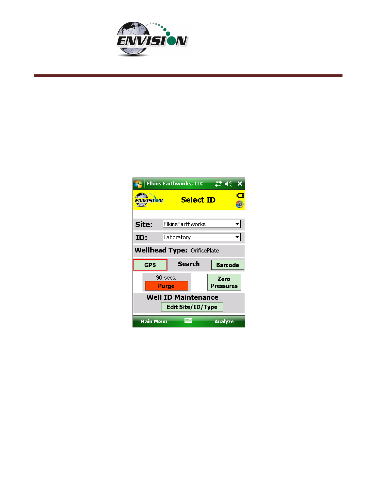
6.6.1 Select ID
To make it easier for a user to locate and identify a well or location to monitor, the Envision® software
utilizes three different search methods: manual, GPS or barcode scanner. In Section 0 there are specific
instructions on how to configure an ID set utilizing the “Elkins Earthworks® Gas Analyzer Configuration
Editor”.
Page 56

P a g e | 56
6.6.1.1 Manually Select ID
On the “Select ID” screen you may manually select the monitoring point by following the instructions
below:
Page 57

P a g e | 57
1) Use the combo boxes labeled “Site” and “ID” to locate the monitoring point that is to be
monitored.
Page 58

P a g e | 58
2) If the “Site” or “ID” is not stored in the ID list, the user can manually create a Site and/or ID
within the “Well ID Maintenance” feature accessible via the “Well ID Maintenance” button at
the bottom of the “Select ID” screen. Instructions on how to Use the “Well ID Maintenance”
function can be found in 6.9.1 “Well ID Maintenance”.
Page 59

P a g e | 59
3) Once the correct ID is selected the user should tap the “Purge” button. The sample pump will
turn on and the button will turn green. The timer will count down 90 seconds or until the O2
percent in the meter is at least 18% then the pump will turn off. The purge cycle may end if
either the Envision® meter detects that the sample train is clear of methane or the user taps
the “Purge” button again.
Page 60

P a g e | 60
4) Once the purge is complete keep your sample trains disconnected and shielded from the wind
then tap the “Zero Pressures” button. The user can also decide to skip the “Zero Pressures”
feature and go directly to the Analyze screen by pressing the “Analyze” button in the lower
right corner of the screen.
Page 61
P a g e | 61
6.6.1.2 GPS Selection of ID
If the user desires to locate the monitoring point via GPS, then follow the instructions detailed below:
1) Stand at the location to be monitored – The first connection may take several minutes for the
GPS to lock after the handheld computer is first turned on. Each location after this should be
instantaneous.
2) Tap the GPS button on the handheld computer’s touch screen.
3) Once the “GPS” button is pushed a status message will be displayed above the Site text box
that will indicate “Reading GPS”, then either “GPS not locked”, “Site/ID selected by GPS”, or
“Failed to find GPS match”.
4) The handheld computer will automatically populate the “Site” and “ID” text box with the
nearest monitoring point.
5) If the GPS does not find a monitoring point, then the status will change to “Failed to find GPS
match”. If the ID is known, the user can manually select the “Site” and “ID” then tap the
“Well ID Maintenance” button to mark the GPS coordinates for that location. Instructions on
how to use the “Well ID Maintenance” function can be found in section 6.9.1.
Page 62

P a g e | 62
6) If sample points are located within 30 feet of each other, then the GPS function will select the
closest point to your location.
6.6.1.3 Barcode Selection of ID
If you desire to select the well to be measured by barcode, please follow the instructions below:
1) Walk up to the point to be monitored
2) Locate the barcode on the item to be monitored
3) On the “Select ID” screen tap the “Barcode” button on the Trimble handheld computer touch
screen and aim the laser scanner at the barcode
Page 63

P a g e | 63
4) A status message will be displayed above the “Site” that will indicate “Scanning Barcode”
5) Once the barcode has been verified the status will change to “Site/ID selected by Barcode”
Page 64

P a g e | 64
6) The handheld computer will automatically populate the “Site” and “ID” text box with the
correct monitoring point.
7) If the barcode does not find a monitoring point, then the status will change to “Failed to find
Barcode match”. If the ID is known, the user can manually select the Site and ID then tap the
“Well ID Maintenance” button to mark the barcode for that location. Instructions on how to
Use the “Well ID Maintenance” function can be found in section 6.9.1.
Page 65

P a g e | 65
6.6.2 Analyze
This feature allows the user to measure the gas qualities and pressures for a selected sample point. The
“Analyze” screen is accessed by pressing the “Analyze” button in the lower right of the “Select ID”
screen.
Note: The typical screen progression is from gas concentration analysis to pressure analysis. However,
if the wellhead type is set to “Probe”, the screen progression is reversed.
6.6.2.1 Analyze Screen (ENV100/200)
6.6.2.1.1 Pump
This button activates the sample pump located within the Envision® gas analyzer.
The left screen is for a typical well. The right screen is for a probe.
The button is red when the pump is off and green when activated. The default on time for the pump is
600 seconds. To activate the pump, tap the “Pump” button once. The sensor will then go through a 20
second warm-up before actual gas values will appear. The pump may be turned off by tapping the
“Pump” button again. If the pump is turned off, then the gas values will return to the default “NA”. To
lock the gas values the user must tap the “Lock Readings” or “Read Pressures”. The pump time can be
Page 66

P a g e | 66
changed within the Configuration Editor as described in section 0.
6.6.2.1.2 Read Pressures
The Envision® unit measures Available, Applied, and Differential pressures. In order to view and record
these pressures the user must go to the “Read Pressures” screen.
The left screen is for a typical well. The right screen comes up if the Wellhead Type is set to “Probe”.
Page 67

P a g e | 67
6.6.2.1.3 Previous Data
If the user desires to view data previously recorded on the handheld computer, then the Previous Data
button should be tapped.
Page 68

P a g e | 68
This button will take the handheld computer to the “View History” screen. The “View History” screen
will display any historical well data for the selected ID located in the site’s current month output file
located on the handheld computer.
To return to the “Analyze” screen tap the Analyze button in the bottom left hand corner of the screen.
Newer software versions have the ability to look back at all previous measurements (below).
Page 69

P a g e | 69
6.6.2.1.4 Enter Temperature
Press the “Enter Temperature” button to allow manual entry of well temperature. This will override any
thermistor that happens to be attached to the Envision.
Page 70

P a g e | 70
Use the hard or soft keypads to enter a temperature value, then hit Ok.
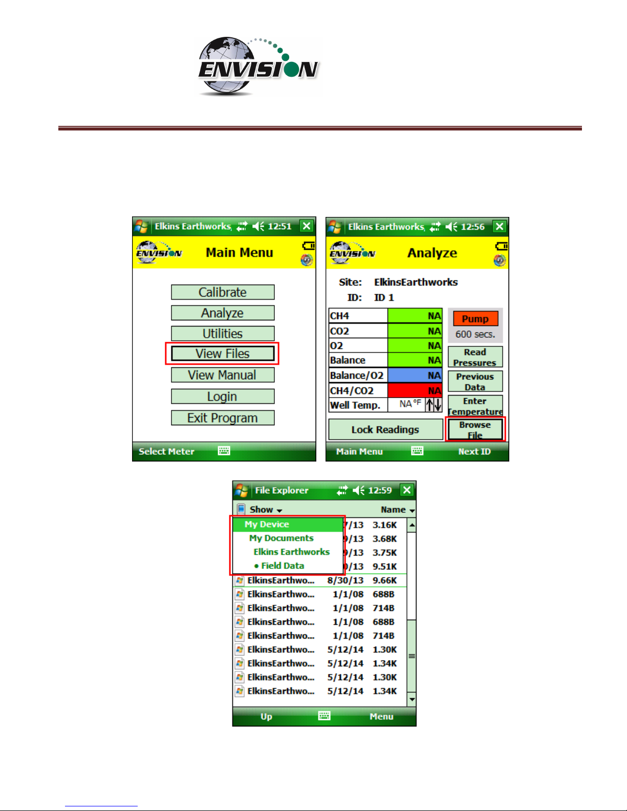
6.6.2.1.5 Browse File
The “Browse File” button will take the handheld computer to the File Explorer.
Page 71

P a g e | 71
This will allow you to search for previously stored .csv (comma separated variable) files for viewing.
Applications are available for the handheld computer that will allow the user to view .csv files.
To return to the “Analyze” screen tap the X in the upper right hand corner of the screen.
6.6.2.1.6 Lock Readings
The “Lock Readings” button is designed to lock the gas values and to turn off the pump. This feature
locks the readings so if you decide to come back to this screen your readings will not change. This
feature does not actually “Store” the gas qualities into the .csv file.
Page 72

P a g e | 72
After the “Lock readings” button is tapped the button will change to “readings saved”. The values are
now locked. The values can be unlocked by tapping the pump button. In order for the data to be
stored to a .csv file the user must tap “Store” on the last analyze screen.
Page 73

P a g e | 73
6.6.2.1.7 Next ID
This button will allow you to select another ID without having to proceed through the entire sample
procedure. However, this will not store any of the data that you have gathered for the current ID.
6.6.2.1.8 Main Menu
This button will exit the user from “Analyze” and take the user back to the “Main Menu”. However, this
will not store any of the data that you have gathered for the current ID.
Page 74

P a g e | 74
6.6.2.2 Analyze Screen (ENVAUS)
The ENVAUS gas analyzer Analyze screen is similar to the ENV100/200 screens above except that it has
an added logging function capability. This allows the user to log gas concentration measurements to a
file. The user can select the total logging time and measurement interval from the “Well ID
Maintenance” screen (see section 6.9.1). The ENVAUS “Analyze” screens are shown below. The logging
timer will count down to zero then stop.
6.6.2.3 Gas Quality and Gas Quality Ratios
The Envision® gas analyzer measures concentrations of three gases: CH4, CO2 and O2. The balance gas
is calculated by subtracting the total of these three gas qualities from 100%.
Page 75

P a g e | 75
6.6.2.3.1 Gas Qualities
CH4 - Methane
CH4 is measured via an internal Infrared sensor. The measurement range of the sensor is 0-100% CH4.
CH4 – LEL (Lower Explosive Limit)
By tapping the CH4 box the handheld computer will display the CH4 LEL%. The user can return to the
standard CH4% by tapping the CH4 box again. Note: 100% LEL is equal to 5% CH4.
CO2 – Carbon Dioxide
CO2 is measured via an infrared sensor. The measurement range of the sensor is 0-100% CO2.
O2 - Oxygen
O2 is measured via an electrochemical sensor. The measurement range of the sensor is 0 – 25% O2.
Balance Gas
Balance gas is a calculated value. It is calculated as follows:
Balance gas = 100%- CH4- CO2- O2
Page 76

P a g e | 76
6.6.2.3.2 Gas Ratios
Balance/ O2
• Results near “4” indicate a direct air leak into the sample train, sample fitting or wellhead.
• User should be familiar with interpreting the range of ratios for Balance/ O
2
. Information is
available within the SWANA Landfill Gas O&M Manual available at www.swana.org.
CH4/ CO2
• Ratio lower than 1.1 may indicate potential for stressed conditions on a landfill gas well.
• The ratio may assist in drawing attention to different phases of landfill gas production.
• User should be familiar with interpreting the range of ratios for CH
4
/ CO2. Information is available
within the SWANA Landfill Gas O&M Manual available at www.swana.org.
Page 77

P a g e | 77
6.6.2.4 Color Definitions
The Elkins Gas Analyzer software has been programmed to help the user make tuning decisions by using
acceptable ranges which have been set up using the Configuration Editor software. When the gas
sensor is in the acceptable range the gas quality text box will turn from red to green. The color key can
be displayed by touching the gas quality text box. Tap “OK” to close the color key.
These ranges are programmable for each well by utilizing the Configuration Editor as detailed in section
0.
Page 78

P a g e | 78
The software is also programmed to detect when the gas sensors have stabilized. When the gas sensor
has stabilized the gas quality text box will turn from clear to green. The color key can be displayed by
touching the sensor title. Tap “OK” to close the color key.
The user may progress to the next screen by pressing the “Read Pressures” button. The user may also
elect to go back to the main menu by tapping the “Main Menu” button.
6.6.3 Read Pressures (ENV100/200)
The Envision® gas analyzer is built with five internal pressure sensors. The software is programmed to
use the sensor that is the most accurate for the range being measured. Listed below are the sensors
and their ranges.
Pressure Sensor
Low Pressure
(“H2O)
High Pressure
(“H2O)
System
NA
-138 to +138
Static
-5 to +5
-138 to +138
Differential
-5 to +5
-30 to +30
Page 79

P a g e | 79
6.6.3.1 Wellhead
When the pressure sensors are in the acceptable programmed range, as programmed by the user in the
Configuration Editor, the pressure text box will turn from red to green. The color key can be displayed
by touching the gas quality text box. Tap “OK” to close the color key.
When the user is satisfied with the Initial pressures they may tap the Lock Initial button to lock in the
initial pressures.
Page 80

P a g e | 80
Once the lock initial pressure button is tapped the “Adjusted” pressures will appear and will start
fluctuating.
Page 81

P a g e | 81
Once the user makes an adjustment and the sensors have stabilized the user can tap the “Lock
Adjusted” button. The button will then change to “Unlock Adjusted”. If the “Unlock Adjusted” button is
pushed it will unlock the adjusted values allowing them to fluctuate. The user may now lock the value
again. Failure to lock the values will result in the adjusted values not being stored in the output file.
The user may also access the pressure sensor calibrate (zero pressures) screen from these screens.
Make sure that the hoses are disconnected and sheltered from the wind when calibrating the pressure
sensors. For calibration instructions refer to section 6.5.3.
Page 82

P a g e | 82
If the user has defined this monitoring point as “User Defined” then the user may type in a flow
measurement for both the Initial and Adjusted flows.
Use the “Comments” button to progress to the next screen or tap the “Analyze” button to go back to
the “Analyze” screen.
Page 83

P a g e | 83
6.6.3.2 Probe
If the Wellhead type is Probe, the screen progression begins with a pressures measurement and ends
with gas concentration measurements. This screen is complete when the user presses the “Lock”
button. Select the “Analyze” button to continue to the gas concentration measurement screens.
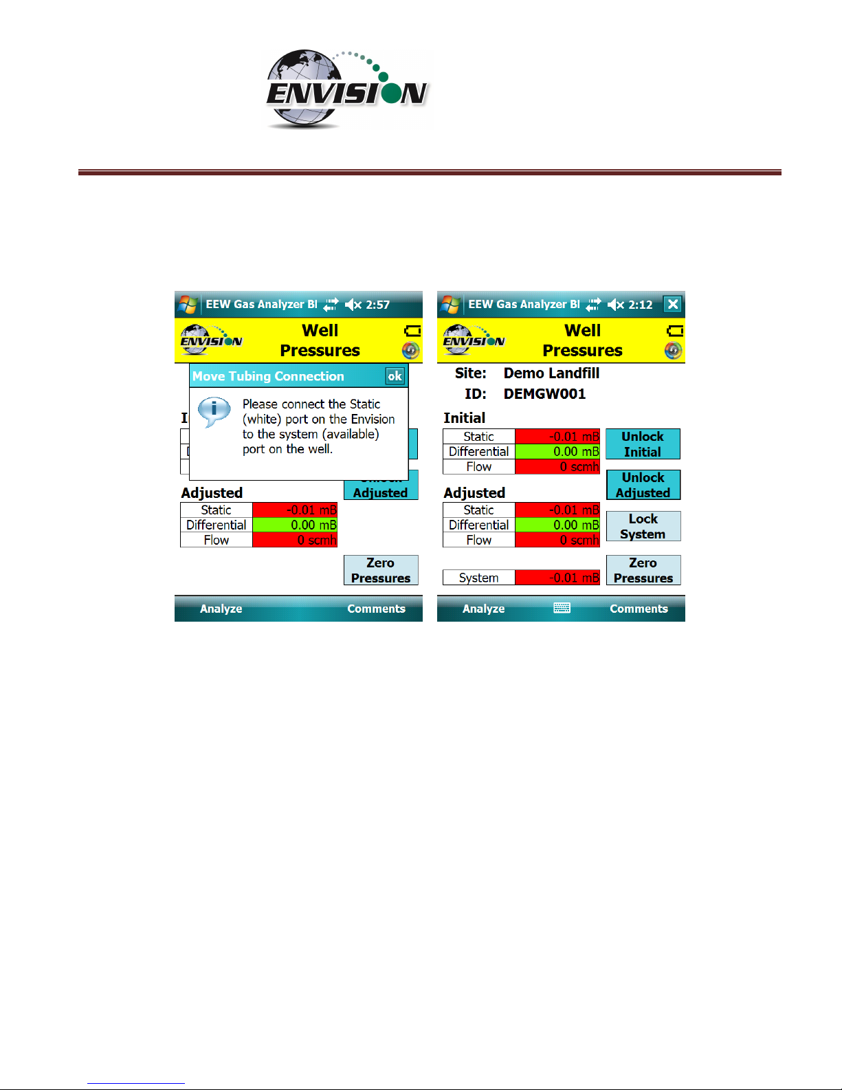
6.6.4 Read Pressures (ENVAUS)
Although the ENVAUS model has much in common with the ENV100/200 sections above, it does not
have the “System” pressure sensor. It uses the “Static” pressure sensor to measure “System” pressure.
Therefore, the user is provided step-by-step, on-screen instructions to guide through the process of
switching tubing. Because of this however, the ENVAUS has the additional capabilities of measuring
borehole flow and atmospheric pressure. See section 13.2 for specifications.
Page 84

P a g e | 84
6.6.4.1 Wellhead Type
The following images show screen progressions for non-borehole wellhead types.
Page 85
P a g e | 85
Because there is no separate pressure sensor to measure “System” pressure on the ENVAUS, the user is
prompted to move the tubing which is connected to the Envision “Static” port to the “System” port on
the well head.
Page 86

P a g e | 86
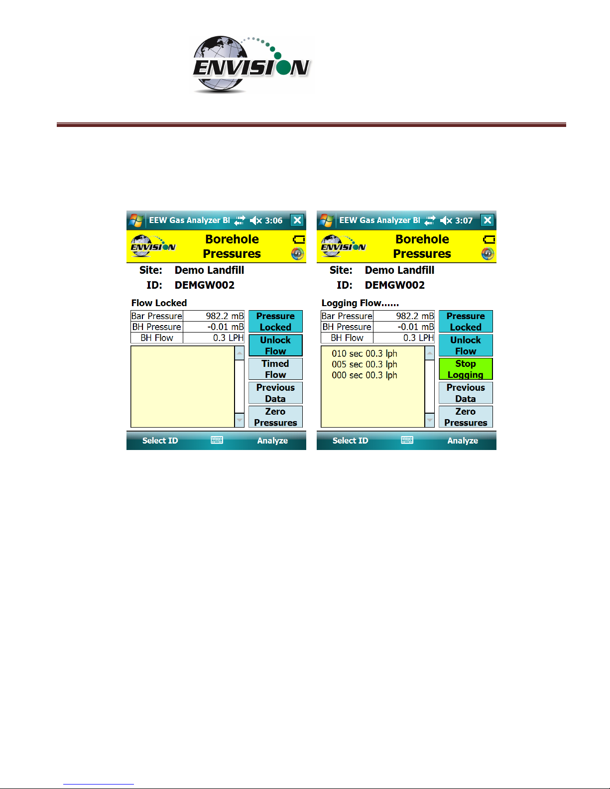
6.6.4.2 Borehole Type
The pressures screen progression for a wellhead of type “BoreHole” is shown below.
Pressing the “Lock Pressure” button brings up the following screens.
Page 87
P a g e | 87
The flow may be locked by pressing the “Lock Flow” button. The user may also select “Timed Flow” to
log the flow measurements to a file. The time interval and total number of measurements may be set
either on the “Well ID Maintenance” screen or in the Configuration Editor.
Page 88

P a g e | 88
6.7 Comments
The comments screen is accessed from the “Pressures” screen (or from the “Analyze” screen for probes
or boreholes). The “Comments” screen is designed to give the user several opportunities to comment
on the sample point.
The user may check boxes from a group of populated comments. These comments are populated by
the use of the Configuration Editor as described in section 0.
Page 89

P a g e | 89
The open text boxes can be populated by tapping on the text box and tapping the keyboard symbol to
open the touch screen keyboard. The user may then type in any comment that is needed.
Once the user is done making comments they may progress to the next screen by tapping the “View
Data” button. The user may also return to the Pressures Screen by tapping the “Pressures” button.
Page 90

P a g e | 90
6.8 View and Store Data
The “View Data” screen is intended to let the user view all of the data collected for this ID. If the user is
satisfied with the data viewed on this screen, then the user can tap the “Store” button to save the data
in the .csv file. If the user is not satisfied with the results, then the user may tap the “Analyze” button
to go back and take the reading again.
Page 91
P a g e | 91
Once the store button is tapped the data is stored in a .csv file on the handheld computer. The data
may be accessed by either pressing “View Files” on the Main Menu or “Browse File” on the Analyze
screen. The files are located in the directory as shown below.
Page 92

P a g e | 92
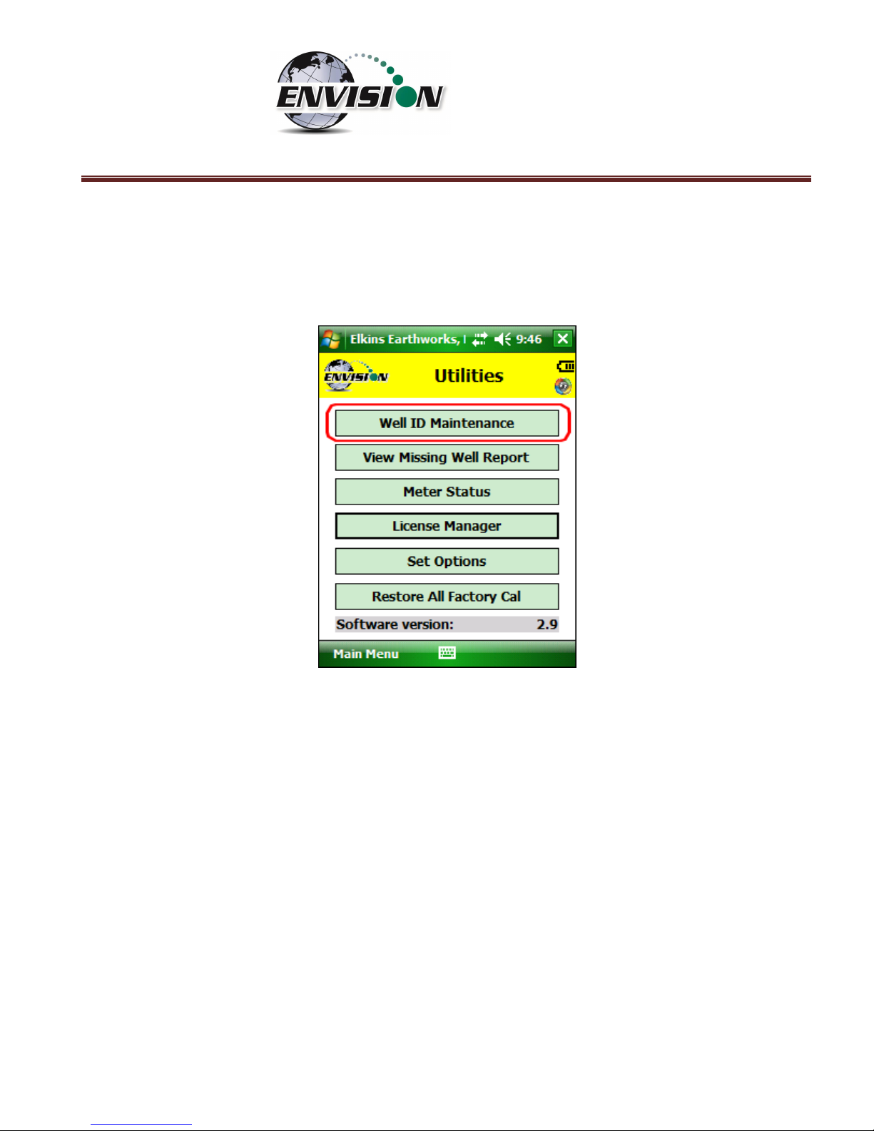
6.9 Utilities
The “Utilities” menu is accessible from the main menu. The “Utilities” menu contains the information
needed to assist in keeping the user informed about the status of the Envision® gas analyzer.
Page 93
P a g e | 93
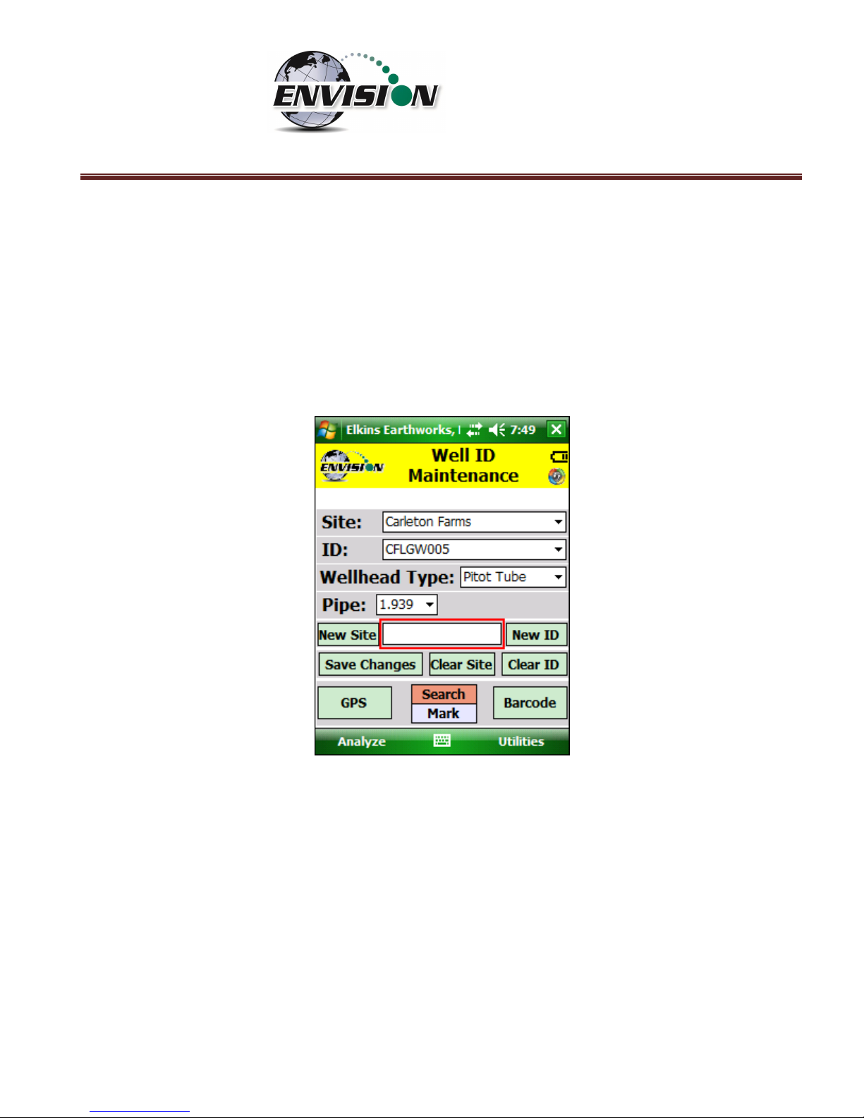
6.9.1 Well ID Maintenance
The “Well ID Maintenance” feature of the utility menu is intended to allow the user to create or delete
ID’s while in the field.
Tapping the “Well ID Maintenance” button will take the user to the “Well ID Maintenance Screen”.
Page 94
P a g e | 94
6.9.1.1 Create New Site
The Well ID maintenance screen will allow the user to make a new site for the existing ID set installed in
the handheld computer. Note: In later versions of the gas analyzer software, the “Clear Site” button
has been removed to protect the user from inadvertently deleting all wells associated with a certain
site. The site may still be cleared using the Configuration Editor software.
1) Tap the text box between the “New Site” and “New ID”.
Page 95

P a g e | 95
2) Open the touch screen keyboard by tapping the key board Icon at the bottom of the touch
screen.
3) Type in the name of the new site
Page 96

P a g e | 96
4) Tap the “New Site” button
5) The new site name will now appear in the “Site” text box and a default ID will be
generated.
Page 97

P a g e | 97
6) Tap the keyboard key to close the touch screen keyboard.
7) The new Site is now stored in the ID set located on the handheld computer.
6.9.1.2 Create New ID
The Well ID maintenance screen will allow the user to make a new site for the existing ID set installed in
the handheld computer.
1) Tap the text box between the “New Site” and “New ID”
Page 98

P a g e | 98
2) Open the touch screen keyboard by tapping the key board Icon at the bottom of the touch
screen.
3) Type in the name of the new ID
4) Drop down the keyboard by tapping the keyboard button
Page 99

P a g e | 99
5) Select the Wellhead Type. If the user desires to manually type in a flow at the selected
point each time, then the user may select user input.
Page 100

P a g e | 100
6) Select the appropriate wellhead “Pipe” size (When applicable).
7) Select the appropriate “Plate” if using an orifice plate.
 Loading...