

Envirovent VENTY ECO2 Air, VENTY ECO2 Loftight Installation Manual For Engineer / Installer
ECO
2
Air & ECO2 Loftight
INSTALLATION GUIDE FOR ENGINEER / INSTALLER
1
ECO2 Air & ECO2 Loftight
0345 27 27 810
SHOULD YOU ENCOUNTER ANY PROBLEMS
INSTALLING THIS UNIT, CALL US ON:
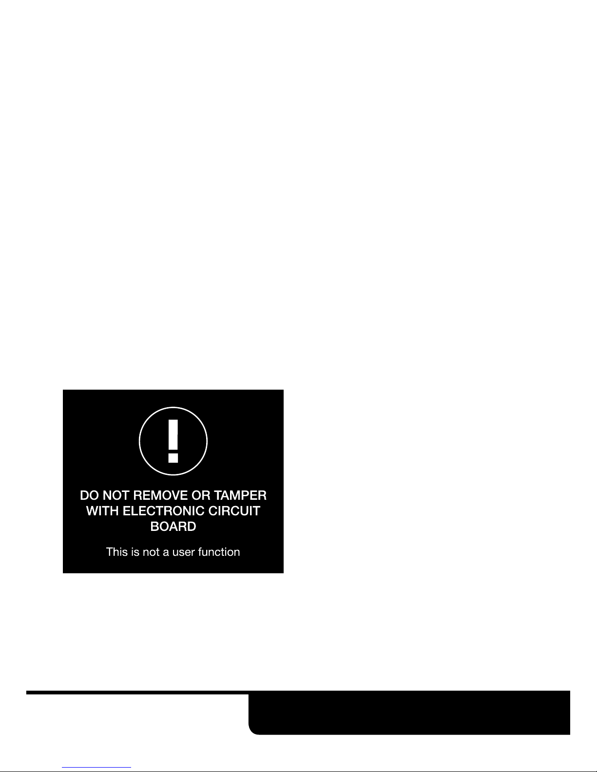
Safety
IMPORTANT
Be sure to have read and understood
these instructions before beginning
the installation process.
Smoke Detectors
It is important that any open side of
the plastic diffuser is not positioned
within 1m of a smoke detector. If the
diffuser cannot be repositioned, up
to two sides of the diffuser may be
closed off using the plastic blanking
plate supplied so that the open sides
face a minimum 1.5m unobstructed
path away from the detector.
SAFETY AND RECOMMENDATIONS
• All wiring must comply with Building
Regulations and the current I.E.E.
Wiring Regulations (BS7671) or
the equivalent standards for your
country. The final installation
should be examined and tested by
a qualified electrician.
• Make sure the mains supply
complies with the rating label for
voltage, frequency and phase.
• This appliance can be used by
children aged from 8 years and
above and persons with reduced
physical, sensory or mental
capabilities or lack of experience
and knowledge if they have been
given supervision or instruction
concerning use of the appliance
in a safe way and understand
the hazards involved. Children
shall not play with the appliance.
Cleaning and user maintenance
shall not be made by children
without supervision.

2
AFTER INSTALLING THIS UNIT,
PLEASE PASS ONTO END USER
DO NOT THROW AWAY
Thank you for choosing EnviroVent
The fastest growing ventilation company in the UK.
You are about to install a product that is designed to outlast the life-cycle of the building.
Once installed the unit will operate continuously for 5 years and beyond without a major
service. Please therefore ensure that this product is treated with care and installed
properly i.e. for the life of the building. If the unit is mishandled you might break it! This
invalidates the warranty.
And remember, if you have any problems please call our dedicated Technical Team. We
are always pleased to help and in an emergency will come out to site quickly, completely
free of charge.
HOTLINE: 0345 27 27 810
Made in Harrogate UK

3
ECO2 Air & ECO2 Loftight
0345 27 27 810
SHOULD YOU ENCOUNTER ANY PROBLEMS
INSTALLING THIS UNIT, CALL US ON:
Description Item
8 X FOAM PADS
4 X PENNY WASHERS
4 X PLASTER BOARD
PLUGS
4 X WOOD SCREWS
(10 X 1.5)
4 X WOOD SCREWS
(10 X 3)
4 X WOOD SCREWS
(8 X 1)
4 X WOOD SCREWS
(8 X 1.5)
ROLL OF INSULATION
TAPE
4 X CABLE TIES
FIXING KIT
Pre-Installation Checklist
Check that the loft has adequate cross flow
ventilation.
Check that all party walls are intact, seek
advice if the wall is missing or broken.
Check that any flue which passes through
the loft is not damaged, seek advice if the
flue is in a poor state of repair.
Check for any flued appliance which may
draw air from the loft, report to the client.
Check for any holes in the ceilings which
may allow leakage of air to the loft and
repair as appropriate.
Check that the water storage tank is
covered.
4
AFTER INSTALLING THIS UNIT,
PLEASE PASS ONTO END USER
DO NOT THROW AWAY
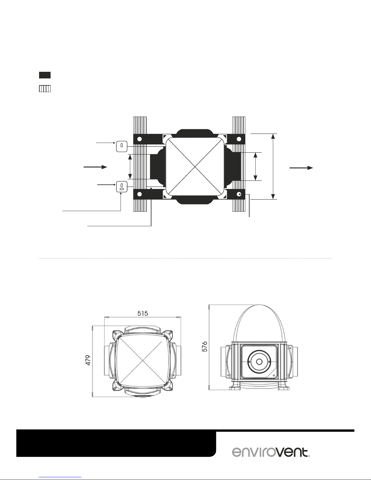
UNIT DIMENSIONS
Dimensions of the ECO2 Air
*Unswitched fuse spur
fitted with 3 Amp fuse
230V A.C.
3 core mains lead
For fixing instructions, please
refer to the fixing instructions
(Fig. A) on page 5
Heater enable/disable
switch (Non-wireless
-Heater version only)
Supply Voltage
• 230V
• 50Hz
• 525W Max
Fresh air
delivered into
dwelling
Fresh air drawn
from outside
Ø200 mm
405 mm
Ø150 mm
650mm x 50mm x 25mm batten
Ceiling joists
Installation Diagrams
STANDARD INSTALLATION
Installation diagram for the ECO2 Air
Contents for unit
1 x Cardboard template
2 x Diffuser
1 x Fixing kit (page 3)
1 x Unswitched fused spur
1m x Ø200mm Flexi duct
1 x Filter
1 x Heater enable switch or
wireless control

5
ECO2 Air & ECO2 Loftight
0345 27 27 810
SHOULD YOU ENCOUNTER ANY PROBLEMS
INSTALLING THIS UNIT, CALL US ON:
Detail
1. As soon as the unit is
secured in desired location,
place the filter on.
2. First locate the rods (provided)
to support the filter.
3. Then velcro the filter into
position.
Installation Instructions
FIRST STAGE
Position a dustsheet beneath the site you have
chosen for cutting the hole for the diffuser. Protect
your lungs with a mask. Enter the loft space with
the ECO2 Air or ECO2 Loftight unit and check there
are no obstructions to your chosen position for
the diffuser. Using the template supplied mark
the hole for the diffuser and cut the 220mm
holes in the plasterboard.
N.B For installations in 3 storey dwellings, the
unit should be linked to the dwellings smoke
alarm system and fitted with a steel fire diffuser,
part number: KIT-PIV-SMOKE.
SECOND STAGE
Position the ECO2 Air or ECO2 Loftight unit on
50mm x 25mm wooden battens (not supplied)
laid across the joists or raised platform if the
insulate is thicker than the joists so that the
trunking between the unit and the diffuser is
not impeded. Lightly screw the drilled battens to
the joist through the rubber mounts and metal
penny washer provided. Fit the trunking to the
unit spigot using half of the tape provided.
THIRD STAGE
Push ducting through the hole in the ceiling.
Return to the hallway and connect the ducting
onto the neck of the diffuser using rest of the
tape provided. Ensure that the diffuser is aligned
correctly with the walls of the hallway. Adjust if
necessary. Fix the diffusers in position using
plasterboard plugs and the screws provided.
FOURTH STAGE
Fit the filter as per the diagram below (ECO2 Air
only).
10 x 3 screw
Penny washer
Foam pad
Foam pad
50mm x 25mm
batten with 20mm
clearance hole
Existing joist
Fig.A Fixing Instructions

6
AFTER INSTALLING THIS UNIT,
PLEASE PASS ONTO END USER
DO NOT THROW AWAY
Installation Instructions
FIFTH STAGE - Fitting the inline filter
Filter location - The filter should be located in the supply airflow between the external input point and
the unit. It is recommended that it is fitted directly to the ECO2 Air Unit spigot in a section of Ø150mm x
350mm (min) ridged duct. See Fig.4.
Filter orientation - The cone filter should always point towards ECO
2
Air unit.
Fixing and sealing - The filter should be fully sealed into the ducting, however it should not be
permanently bonded into position, this is to allow for removal of the filter during maintenance. Use a
flexible section as shown in Fig 1 & Fig 4 to aid removal, 300mm is recommended. Always apply the
label provided to the filter location, this is to assist future filter maintenance (Fig 3).
Installation configurations - For sample configurations see (Fig 2).

7
ECO2 Air & ECO2 Loftight
0345 27 27 810
SHOULD YOU ENCOUNTER ANY PROBLEMS
INSTALLING THIS UNIT, CALL US ON:
Installation Instructions
Maintenance - For maximum efficiency of the unit, it is recommended that the filter is cleaned every
24 to 36 months by a competent person. Use a vacuum cleaner, a soft brush or warm water (air dry fully
before replacing).
Size
Fig 3.
Fig 4.
Filter Assembly
Filter
Ø150mm x 350mm Link
Seal Seal, if required
Ridged / FlexiDuct
300mm
Flexi Section
ECO
2
Air

8
AFTER INSTALLING THIS UNIT,
PLEASE PASS ONTO END USER
DO NOT THROW AWAY
Installation Instructions
SIXTH STAGE
Choose a location for the fresh air intake and
drill a Ø158mm (or Ø132mm) hole for wall kit.
Depending on the layout of your attic, you have
three options for locating the input of fresh air
(wall input; roof input and under tiles input).
If Ø125mm wall / roof kit is installed, use an
Ø150mm adaptor to connect to the unit with
Ø150mm insulated ducting. Make sure that all
connections are sealed well.
It is recommend that Ø150 intake vent is used for
best performance.
Delivering Fresh Air - Options
Fresh air drawn from outside - Wall Input
Fresh air drawn from outside - Under Tiles
Input
Fresh air drawn from outside - Roof Input
SEVENTH STAGE
The ECO2 Air and ECO2 Loftight units must only be
installed by a competent person and should be
connected to an electrical supply in accordance
with the current electrical regulations. A
disconnection device should be used in the fixed
wiring. Connect the heater enable cable to the
switch provided (non wireless versions only).
EIGHTH STAGE
Check the unit is working correctly. Set the unit’s
controls according to the house size and check
that the filters are securely in place.
1
2
3
Solar Gain
1
2
3
PRESS BUTTON
LARGE
PRESS
BUTTON
PRESS
BUTTON
PRESS
BUTTON
SMALL /
TRICKLE
MEDIUM BOOST
NINTH STAGE - Manual settings
Method of operation: Adjust the settings on the top of the unit by pressing the house setting button. By
pressing the button, the correct ventilation rate for the size of the house can be selected i.e. if the unit
is on SMALL / TRICKLE and the button is pressed, the unit will then switch to MEDIUM. Similarly, if the unit
is on BOOST and the button is pressed, the unit will then switch to SMALL / TRICKLE. The manual setting
panel can be found on the side of the ECO
2
Air unit and top of the ECO2 Loftight unit.

9
ECO2 Air & ECO2 Loftight
0345 27 27 810
SHOULD YOU ENCOUNTER ANY PROBLEMS
INSTALLING THIS UNIT, CALL US ON:
Installation Instructions
NINTH STAGE cont. - Wireless units only
To pair additional remote control switches:
1. Turn the unit off at the isolation point.
2. Restore power; for 20 seconds from restart
the unit will be in pairing mode.
3. Press the remote button once within the 20
seconds and the control will pair to the unit.
4. Successful pairing is indicated by a green
light on the control.
N.B: When the battery needs replacing, unscrew
the front cover. The battery is located on the
back of the cover.
Battery type - 3V Lithium, CR2032.
To change speed setting
Next press moves the unit to the
next speed and so on. When the
speed is chosen the LED remains
on for a few seconds
On commission the unit will
default to the trickle flow rate
with heater enable on
Press button once, to indicate
current fan speed and heater
status. LEDs stay on constant
for a few seconds

10
AFTER INSTALLING THIS UNIT,
PLEASE PASS ONTO END USER
DO NOT THROW AWAY
If the two LEDs situated just
above the button flash alternately
red and green (when it is
pressed) the control will need
to be reprogrammed. Call your
maintenance company or
EnviroVent for advice.
Heater enable ON
Auto LED stays on constant for a few seconds.
Heater enable OFF
Auto LED flashes for a few seconds.
Boost
(Green)
(Green)
Remote Control out
of range (Red)
Heater enable
(Red)
Remote Control in
range (Green)
LED Colours
Constant Red
Flashing Red
Constant Green
For heater enable/disable
Press button for five
seconds turns heater
enable off. LED will flash
red for a few seconds
Press button for five seconds
turns heater enable on. LED
will show constant red for a
few seconds

EnviroVent Ltd
EnviroVent House
Hornbeam Business Park
Harrogate
HG2 8PA
T / 0345 27 27 807
F / 01423 301 022
E / enquiries@envirovent.com
W / envirovent.com
E&OE | MKT ENV247-V4-08.03.17
Due to our policy of continuous innovation
and improvement EnviroVent reserves the
right to alter products specification and
appearance without notice.
We want to hear from you
Your feedback is important to us as we strive to improve our
products, services, and overall customer experience. Please email
us to help us serve you better: feedback@envirovent.com
AFTER INSTALLING THIS FAN PLEASE PASS ONTO END USER
DO NOT THROW AWAY
Delivering innovative and sustainable
ventilation solutions worldwide
Please read carefully to ensure
simple installation and a long
trouble free life for the user.
 Loading...