

Page 1
Page 2
SHOULD YOU ENCOUNTER ANY PROBLEMS INSTALLING THIS UNIT CALL
01
01 Safety Instructions
IMPORTANT
Be sure to have read and understood these
instructions before beginning the installation
process.
PRE-INSTALLATION CHECK LIST
Make sure that the unit can physically t in to
the desired location.
SAFETY AND RECOMMENDATIONS
• This appliance can be used by children
aged from 8 years and above and
persons with reduced physical, sensory or
mental capabilities or lack of experience
and knowledge if they have been given
supervision or instruction concerning
use of the appliance in a safe way and
understand the hazards involved. Children
shall not play with the appliance. Cleaning
and user maintenance shall not be made
by children without supervision.
Installation must take place under:
• Quality requirements ventilation systems
dwellings.
• Quality requirements balanced ventilation
in dwellings.
• The regulations for ventilation of dwellings
inand residential buildings.
• The safety regulations for low-voltage
installations.
• The regulations for connection to interior
sewers in dwellings and residential
buildings.
• Any additional regulations of the local
utilities.
• The installation instructions for the Slimline
150
Page 3
AFTER INSTALLING THIS UNIT PLEASE PASS ONTO END USER
DO NOT THROW AWAY
02
02 Technical Specications
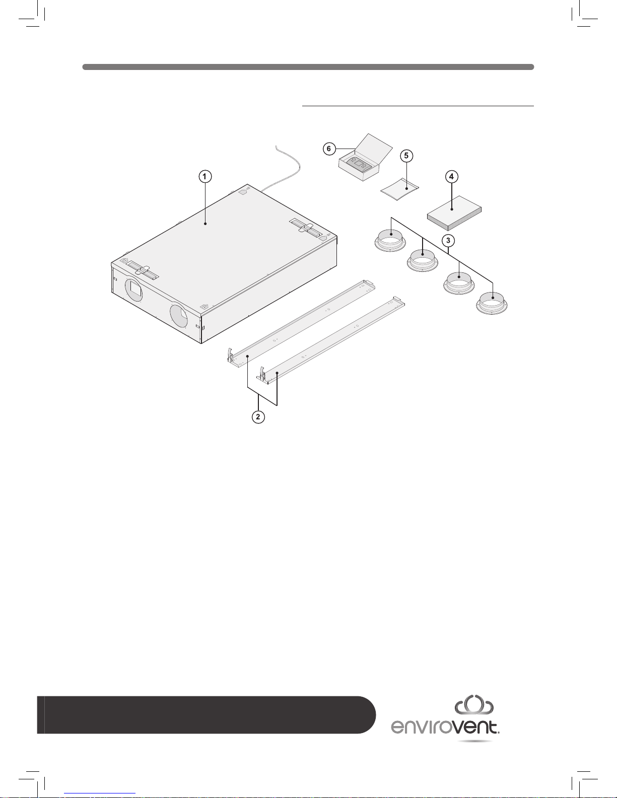
Before you begin to install the heat recovery unit, check that it has been supplied complete and undamaged.
The Slimline 150 unit should include the following components:
1. Heat recovery appliance
2. Wall mounting bracket kit; - 2x suspension strips
3. Duct connecting kit; - 4x collars Ø125 mm
4. Documentation set; - 1x installation instructions
5. Connecting kit; - Mounting material collars, including 16 xing screws
- Connectors : 2-pole screw connector (eBus) and 9-pole screw connector only
for Plus version)
6. Control unit with operating manual
Page 4
SHOULD YOU ENCOUNTER ANY PROBLEMS INSTALLING THIS UNIT CALL
03
The EnviroVent Slimline 150 is a ventilation
unit with heat recovery with a maximum
ventilation capacity of 150 m
3
/h and low-
energy fans.
Slimline 150 Features:
• Steplessly adjustable air ow rates through
a control unit (supplied with appliance).
• Filter indication on the control unit / multiple
switch.
• A completely new intelligent frost
protection system. This ensures that
even at low outdoor temperatures the
appliance’s performance remains optimal
and that, if necessary, it activates the
standard preheater.
• Low sound level
• Comes as standard with automatic bypass
valve
• Constant ow control
• Low energy consumption
• High eciency
Slimline 150 is available in two types:
• Slimline 150
• Slimline 150 Plus
Compared to the Slimline 150, the Slimline
150 Plus has a more extensive control board
which increases the connection options.
These installation instructions describe both
the standard Slimline 150 and the Slimline
150 Plus.
With the aid of the supplied mounting
brackets, the Slimline 150 (Plus) can be
mounted either on the wall or on the ceiling.
For the correct position of the connection
ducts and dimensions see page 6.
When ordering an appliance always state
the correct type; subsequent conversion to
a dierent version is highly labour-intensive.
The Slimline 150 comes ready to wire into
the 230V mains fused spur.
The appliance comes as standard with a
control unit, but connection of a simple
4-way switch is possible as well.
If a 4-way switch is installed instead of a
control unit, the settings of the appliance
can only be changed with a laptop.
Connecting a combination of control unit
and multiple switch is another option.
02 Technical Specications
Page 5
AFTER INSTALLING THIS UNIT PLEASE PASS ONTO END USER
DO NOT THROW AWAY
04
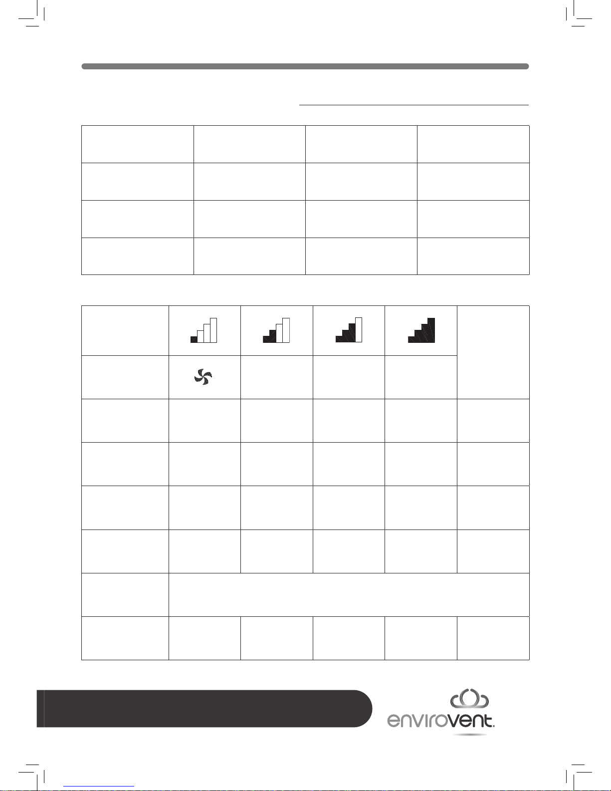
Supply voltage (V/Hz) 230/50 Protection degree IP30
Dimensions
(w x d x h) (mm)
1000 x 660 x 198 Duct diameter (mm) Ø125
External discharge 3/4 Weight (kg) 24.5
Filter class G4
Fan factory setting
(control unit)
MAX
4-Way switch 1 2 3
Ventilation capacity
(m
3
/h)
30 75 100 125 150
Permissible
resistance ducts
system (Pa)
2-6 13-38 22-66 35-105 50-150
Rated power (excl.
optional pre-heater)
(W)
11-12 19-27 27-37 38-52 53-72
Rated current (excl.
optional pre-heater)
(A)
0.14-0.15 0.20-0.28 0.27-0.35 0.36-0.47 0.49-0.64
Rated current (incl.
optional pre-heater)
(A)
2.4
Cos φ 0.34 0.42 0.44-0.47 0.46-0.48 0.47-0.49
02 Technical Specications
Page 6
SHOULD YOU ENCOUNTER ANY PROBLEMS INSTALLING THIS UNIT CALL
05
0
50
100
150
200
0 25 50 75 100 125 150 175
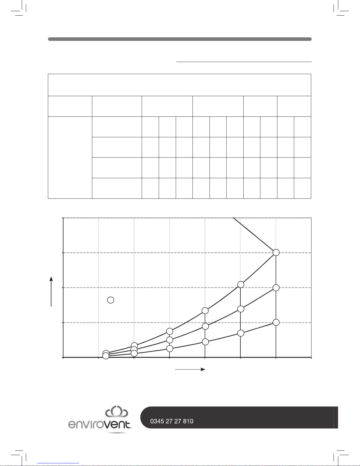
= [W]
x
36
27
19
13
9
32
23
17
12
8
12
14
19
27
7
9
5
Sound Power
Ventilation
capacity (m
3
/h)
45 75 105 150
Sound power
level Lw (A)
Static pressure
(Pa)
10 50 100 25 50 100 50 100 50 100
Housing emission
dB(A)
24 33 39 33 35 40 38 41 44 45
Duct “from
dwelling” dB(A)
27 36 42 34 37 42 40 43 46 47
Duct “to dwelling”
dB(A)
41 49 58 50 53 57 57 60 62 64
Note: In practice, the value may deviate 1 dB(A) as a result of measuring tolerances.
(Pa)
(m3/h)
Note: The value stated in the circle is the capacity per fan (in Watt)
02 Technical Specications
Page 7
AFTER INSTALLING THIS UNIT PLEASE PASS ONTO END USER
DO NOT THROW AWAY
06
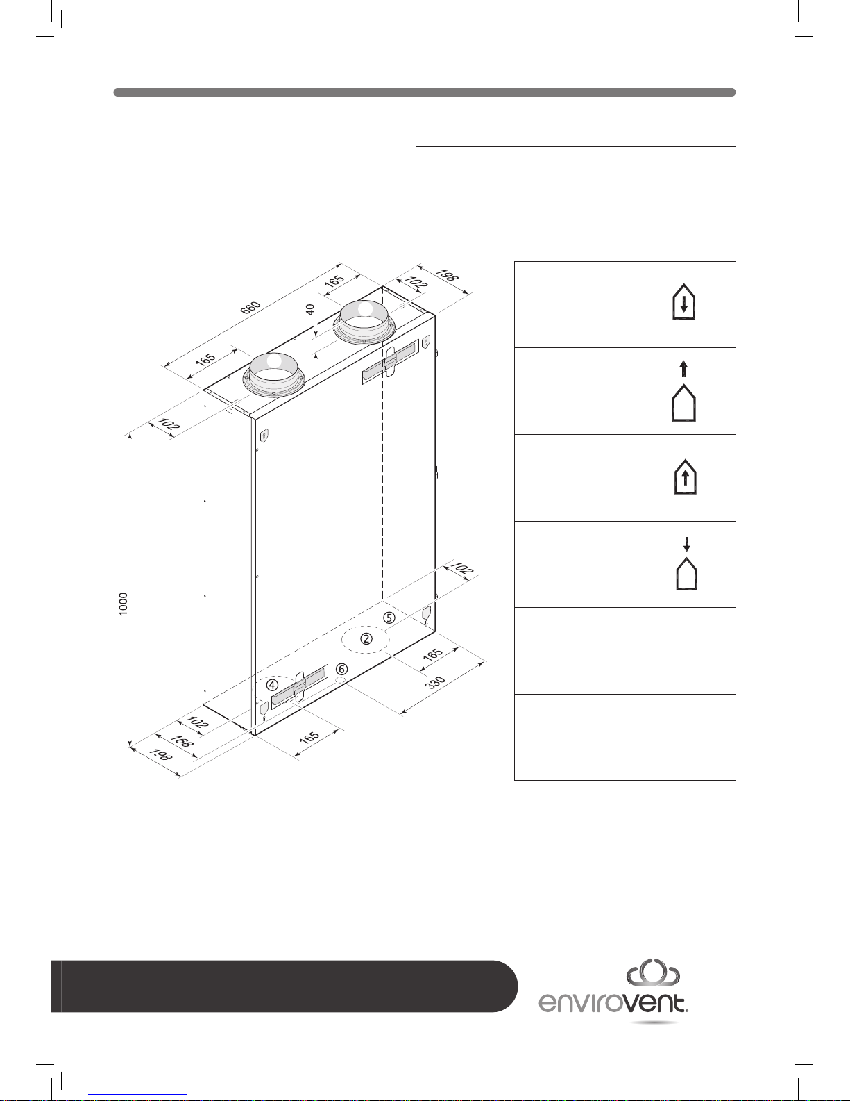
1. To dwelling
2. To atmosphere
3. From dwelling
4. From
atmosphere
5. Electric connections
6. Connection condensate
discharge
02 Technical Specications
Page 8

SHOULD YOU ENCOUNTER ANY PROBLEMS INSTALLING THIS UNIT CALL
07
1. Extract air lter
2. Indoor temperature sensor
3. Bypass
4. Condensate bin
5. Extract fan
6. Locking screw front panel
(mounted in front panel)
7. Connector X14
8. Control board
9. Connector X4
10. Condensate discharge
11. Supply air lter
12. Preheater
13. Outdoor temperature sensor
14. Heat exchanger
15. Supply fan
16. Modular connector multiple switch
17. Service connector
18. Sleeve low voltage cable
19. Sleeve cable 230V postheater or
extra preheater
20. Mains cable 230V
21. 9-pole connector (only for Plus version)
22. Connector eBus
23. Fall protection front panel
02 Technical Specications
Page 9

AFTER INSTALLING THIS UNIT PLEASE PASS ONTO END USER
DO NOT THROW AWAY
08
The appliance is supplied ready to wire into
the fuse spur and operates fully automatically.
The extracted indoor air heats up the fresh,
clean outdoor air. That saves energy and
fresh air is sent to the required rooms.
The control system has four ventilation
modes. The air ow rate can be adjusted
per ventilation mode. The constant volume
control system ensures that the air ow
rate of the supply and extract fans is
always delivered despite any resistance
encountered in the ductwork.
The standard bypass valve makes it possible
to supply fresh outside air that is not heated
by the heat exchanger. Particularly during
summer nights it is desirable to supply
cooler outside air. In this mode the hot air in
the dwelling is replaced by cooler outside air
as far as possible.
The bypass valve opens and closes
automatically when a number of conditions
are satised (refer to the table below for
bypass conditions).
The operation of the bypass valve can be
adjusted in step number 5, step number 6
and step number 7 in the settings menu (see
pages 39-41).
To prevent freezing of the heat exchanger
at extremely low outdoor temperatures,
the Slimline 150 features an intelligent frost
control. Temperature sensors measure the
temperatures across the heat exchanger
and, if necessary, the preheater is switched
on. This guarantees a proper ventilation
balance, even at very low outdoor
temperatures.
If, with switched on standard preheater(s),
the exchanger temperature still starts to drop
below zero, stepless unbalance is created in
the appliance.
The user information menu shows when the
Slimline 150 frost control system is activated
(see page 19).
Bypass valve open
-The outdoor temperature is higher than 10°C and
-The outdoor temperature is lower than the indoor temperature in the
dwelling and
-The temperature in the dwelling is higher than the temperature set at step
no.5 in the settings menu
(set a standard at 22°C).
Bypass valve closed
-The outdoor temperature is lower than 10°C or
-The outdoor temperature is higher than the indoor temperature in the
dwelling or
-The temperature from the dwelling is lower than the temperature set at
step no. 5 in the settings menu minus the set temperature by the hysteresis
(tolerance) (step no. 6), this temperature is factory set at 20°C (22.0°C
minus 2.0°C).
02 Technical Specications
Page 10
SHOULD YOU ENCOUNTER ANY PROBLEMS INSTALLING THIS UNIT CALL
09
02 Technical Specications
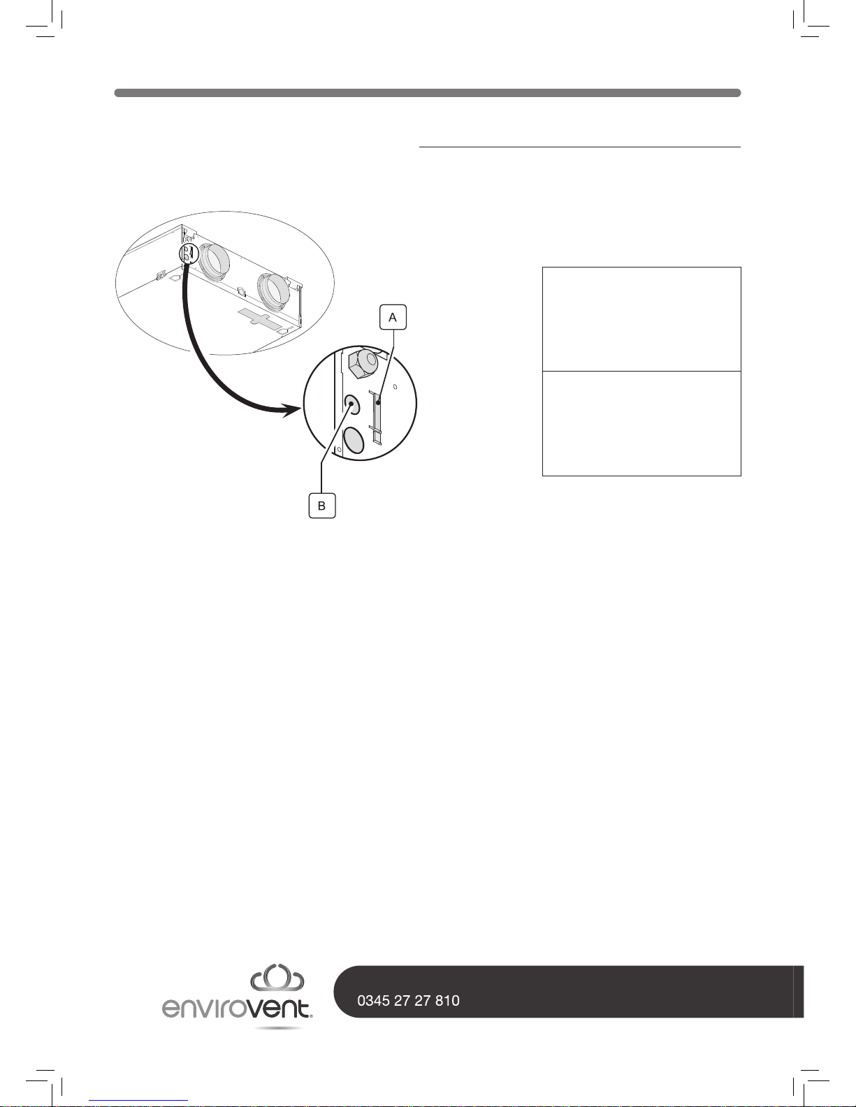
The Slimline 150 is also available as a Plus
version. This version is equipped with a
dierent control board with 2 additional
connectors (X14 & X15) with more
connection options for various applications.
Only the Plus is equipped with a 9-pole
connector (connected to X15 on control
board) that is accessible from the outside of
the appliance.
If a postheater or extra preheater is
connected to connector X14 (accessible
after opening the front panel ) the installer
must feed the connected 230 Volt cable
to outside the appliance through a strain
reliever. For this strain reliever (not supplied
with the appliance) a plug must be removed
from the position where this strain relief
must be placed.
See page 32 for more information on the
connection possibilities of connectors X14
and X15.
A. 9-pole connector
B. Hole for gland to be
mounted by installer (for
sleeve cable postheater/ extra
preheater).
Slimline 150 Plus
Page 11
AFTER INSTALLING THIS UNIT PLEASE PASS ONTO END USER
DO NOT THROW AWAY
10
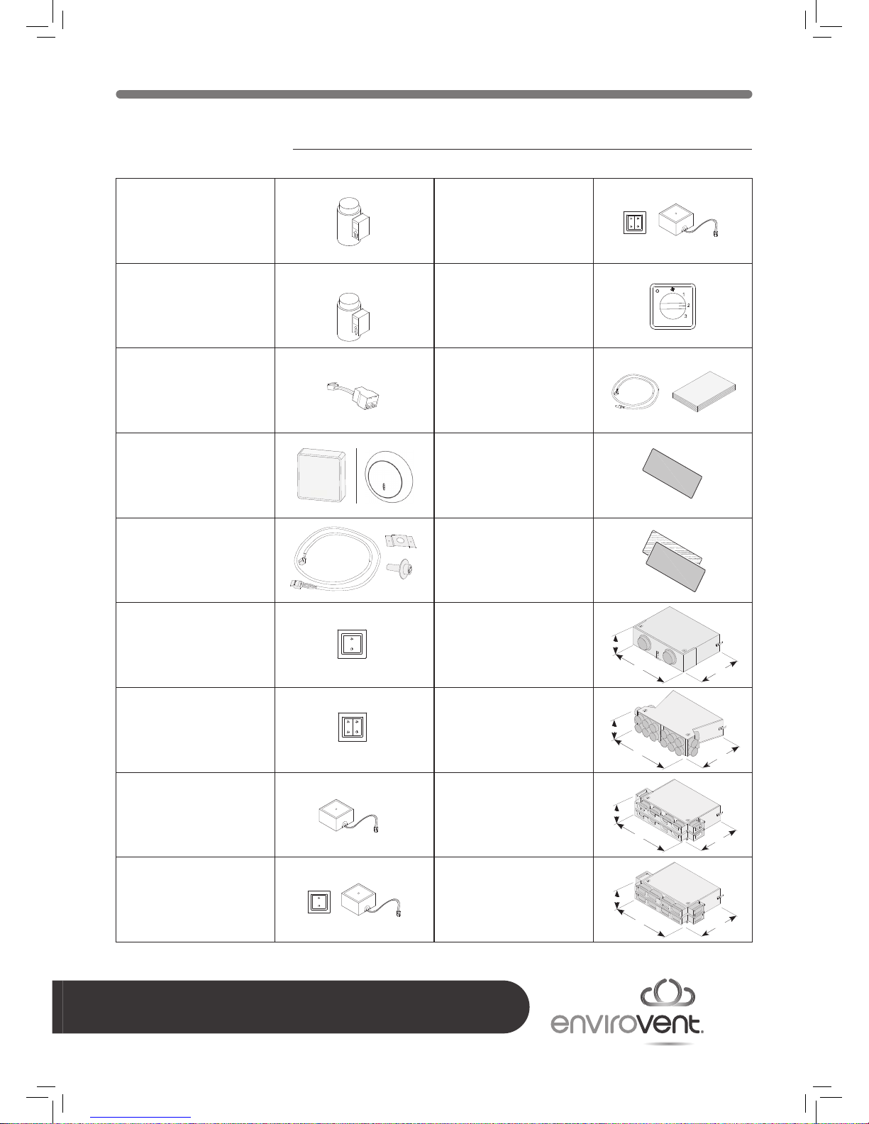
03 Accessories
Electric post-heater
Kit wireless remote
control 4 positions (1
transmitter & 1 receiver)
Electric pre-heater
4-way switch with lter
indication; ush
mounted; modular
connection
Splitter RJ12 Service tool
CO
2
sensor, ush
mounted eBus or
surface mounted
0-10V proportional
(PLUS version only)
Filter kit 1x F7 lter
RH sensor Filter kit 1x G4 & 1x F7
Transmitter wireless
remote control 2
positions (with battery)
Silencer box Ø125 mm
(2x)
Transmitter wireless
remote control 4
positions (with battery)
Silencer- / air distribution
box Ø75 mm (20x)
Receiver wireless
remote control
(for battery version)
Silencer- / air distribution
box 100 x 50 mm (12x)
Kit wireless remote
control 2 positions (1
transmitter & 1 receiver)
Silencer- / air distribution
box 130 x 60 mm (12x)
F7
2x G4
F7
G3 +F7
G4 +F7
2X G3
2x G4
G4 + Frame
Please contact EnviroVent for order codes
482 mm
660 mm
200 mm
482 mm
660 mm
200 mm
482 mm
660 mm
200 mm
482 mm
660 mm
200 mm
Page 12

SHOULD YOU ENCOUNTER ANY PROBLEMS INSTALLING THIS UNIT CALL
11
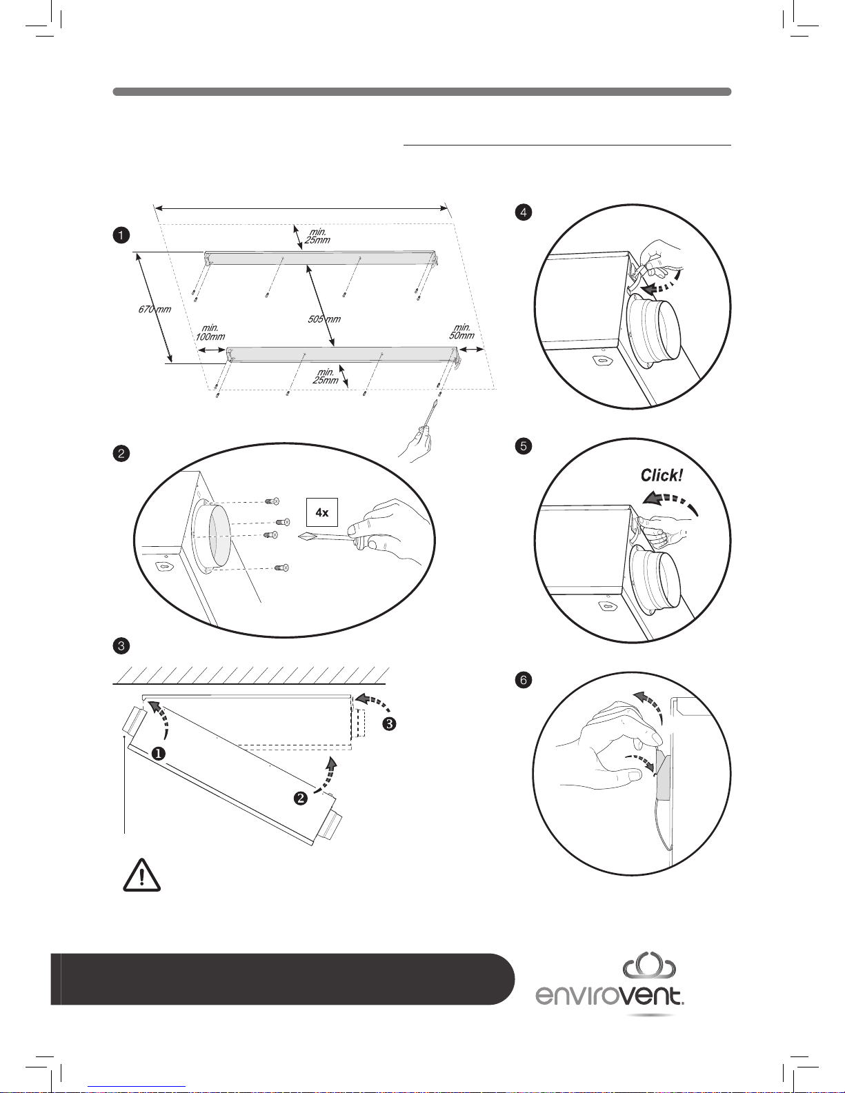
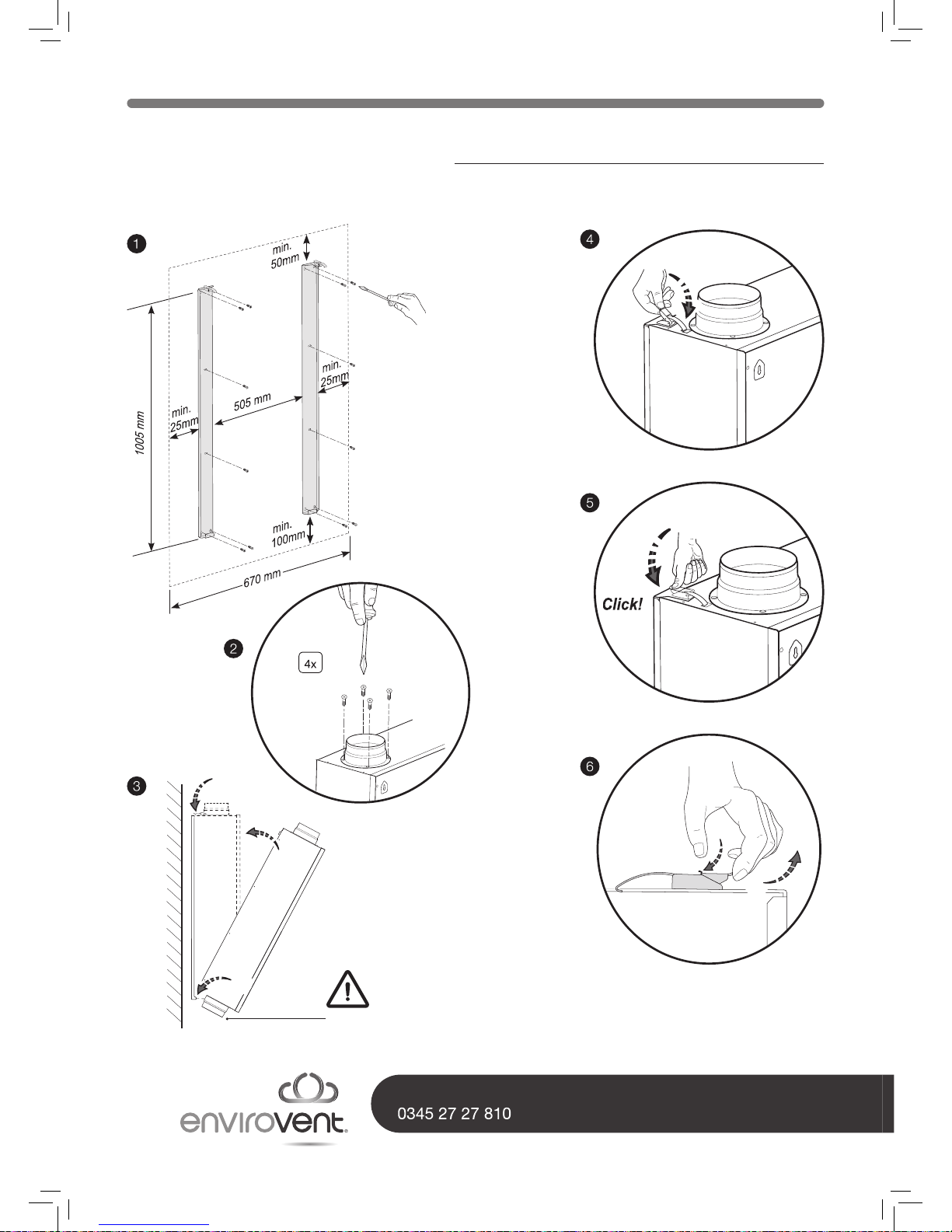
The Slimline 150 can be mounted directly
to the wall or ceiling using the mounting
brackets supplied for that purpose.
Because of the appliance’s weight,
mounting the appliance must
always be done by two people.
For a vibration-free result the appliance must
be mounted to a solid wall with a minimum
mass of 200 kg/m
2
. A gypsum block or
metal stud wall will not suce. Additional
measures such as double panelling or extra
studs are required in that case. In addition,
the following aspects must be taken into
account.
• The appliance must be placed level; both
lengthwise and laterally.
• The installation room must be such that a
good condensate discharge with air trap
and pitch for condensate can be made.
Make sure that under no condition
the condensate discharge is
installed at a pitch towards the
appliance.
The appliance is only suitable for
ceiling or wall mounting! Never
mount the appliance at on the
oor because of the position of the
condensate discharge bin.
• The installation room must be frost-free.
• When mounting exible ducts, bear in
mind that it must be possible to replace
them in due course.
• Make sure there is sucient free space
at the appliance to allow cleaning of the
lters and maintaining the appliance. It
must be possible to swing the door open.
Ceiling mounting:
At least 70 cm at the underside of the
appliance and a free headroom of 1.8 m; if 70
cm free space is not available, for instance
when mounting on top of a suspended
ceiling, there must be sucient room to
partly open and remove the front panel.
The front panel can be detached after
removing a lock screw at the hinge.
Make sure the lters can always be freely
removed, so there is no frame or other
obstacle at the level of the lters!
Wall mounting:
Make sure there is a free space of at least 70
cm at the front of the appliance and a free
headroom of 1.8 m.
Make sure there is at least 20 cm free space
at the appliance side where the electric
connections are located, so connectors and
sleeves remain accessible.
04 Installation Instructions
Page 13
AFTER INSTALLING THIS UNIT PLEASE PASS ONTO END USER
DO NOT THROW AWAY
12
Placing the appliance for ceiling mounted
04 Installation Instructions
Appliance disconnecting from
mounting bracket
Condensate discharge
Page 14
SHOULD YOU ENCOUNTER ANY PROBLEMS INSTALLING THIS UNIT CALL
13
Placing the appliance for wall mounted
Condensate discharge
Appliance disconnecting from
mounting bracket
04 Installation Instructions
Page 15
AFTER INSTALLING THIS UNIT PLEASE PASS ONTO END USER
DO NOT THROW AWAY
14
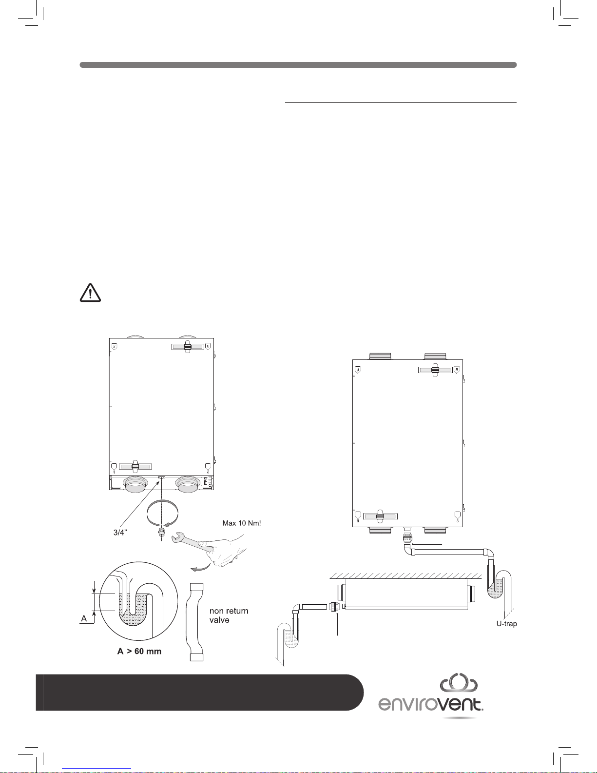
Detachable coupler
Detachable coupler
The Slimline 150 must always be tted with a
condensate discharge. The condensate must
be discharged through a drainpipe.
EnviroVent
recommend using KITCONDENSATE-BK.
The condensate discharge connection
with 3/4” mail thread (not supplied with
the appliance) must be screwed into the
appliance’s condensate bin by the installer.
Important:
Always install a detachable coupler
in the condensate discharge line as
closely as possible to the appliance,
otherwise the condensate bin cannot
be removed from the appliance for
service purposes.
The condensate discharge line can be mounted
to it, preferably glued, if necessary using a square
bend. The installer can glue the condensate
discharge to the appliance in the desired
position. The drain must discharge under the
water level in the U-trap. Use a condensate
discharge line with a diameter of 32 mm.
Particularly for ceiling mounting, make sure
the condensate discharge is below the level
of the condensate bin in the Slimline 150.
Before connecting the condensate discharge
to the appliance, pour water into the U-trap to
create an air trap.
Note: Add a teaspoon of oil to prevent drying
out. Alternatively use a non return valve in
place of the U-trap.
04 Installation Instructions
Recommended
(KITCONDENSATE-BK)
Page 16
SHOULD YOU ENCOUNTER ANY PROBLEMS INSTALLING THIS UNIT CALL
15
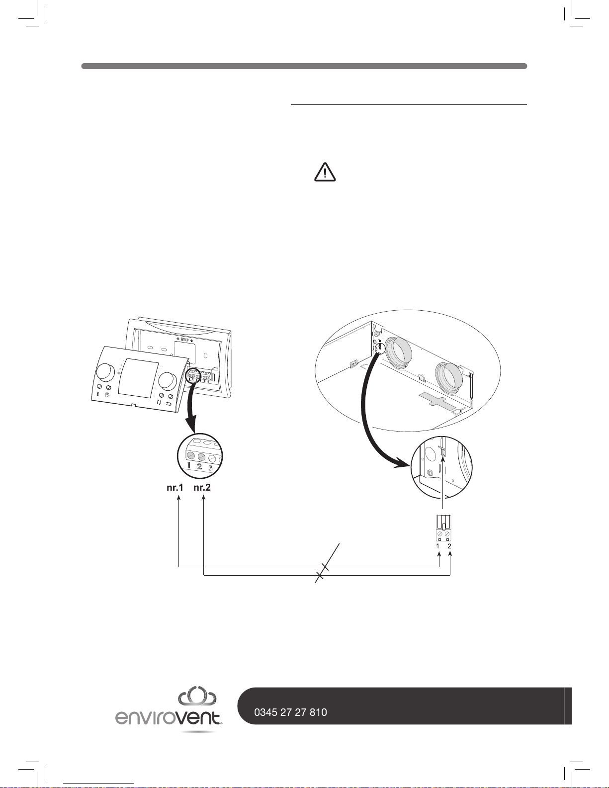
The appliance can be connected to an
easily accessible fused spur. The electric
installation must comply with the wiring
regulations.
The appliance
Make allowance for the 375 W preheater; if in
addition also a postheater or extra preheater
is installed, the rated power increases to
447W.
Warning
The fans and control board carry
a high voltage. Always remove
the voltage from the appliance by
isolating power when working on
the appliance.
The control unit that comes as standard with
the appliance must be connected to the
eBus connector. This (detachable) 2-pole
eBus connector is mounted on the outside
of the appliance (see page 33).
Cables to be connected by installer
(wire diameter at least 0.34 mm
2
)
04 Installation Instructions
Page 17
AFTER INSTALLING THIS UNIT PLEASE PASS ONTO END USER
DO NOT THROW AWAY
16
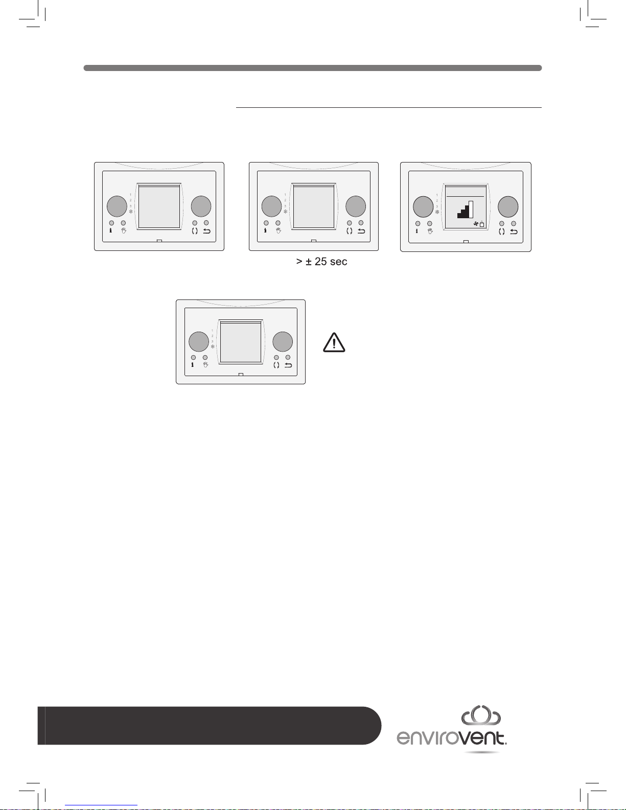
Warning
When working on the appliance,
always remove the voltage from the
appliance by rst switching it o
through software and then isolating
the power.
Connecting
Software
S1.03.03
08:0 0 23:0 0 -
08 :30
23.01.12Sonntag
FILTER
Sunday
05 Control Display
Switching the appliance ON/OFF
Page 18
SHOULD YOU ENCOUNTER ANY PROBLEMS INSTALLING THIS UNIT CALL
17
05 Control Display
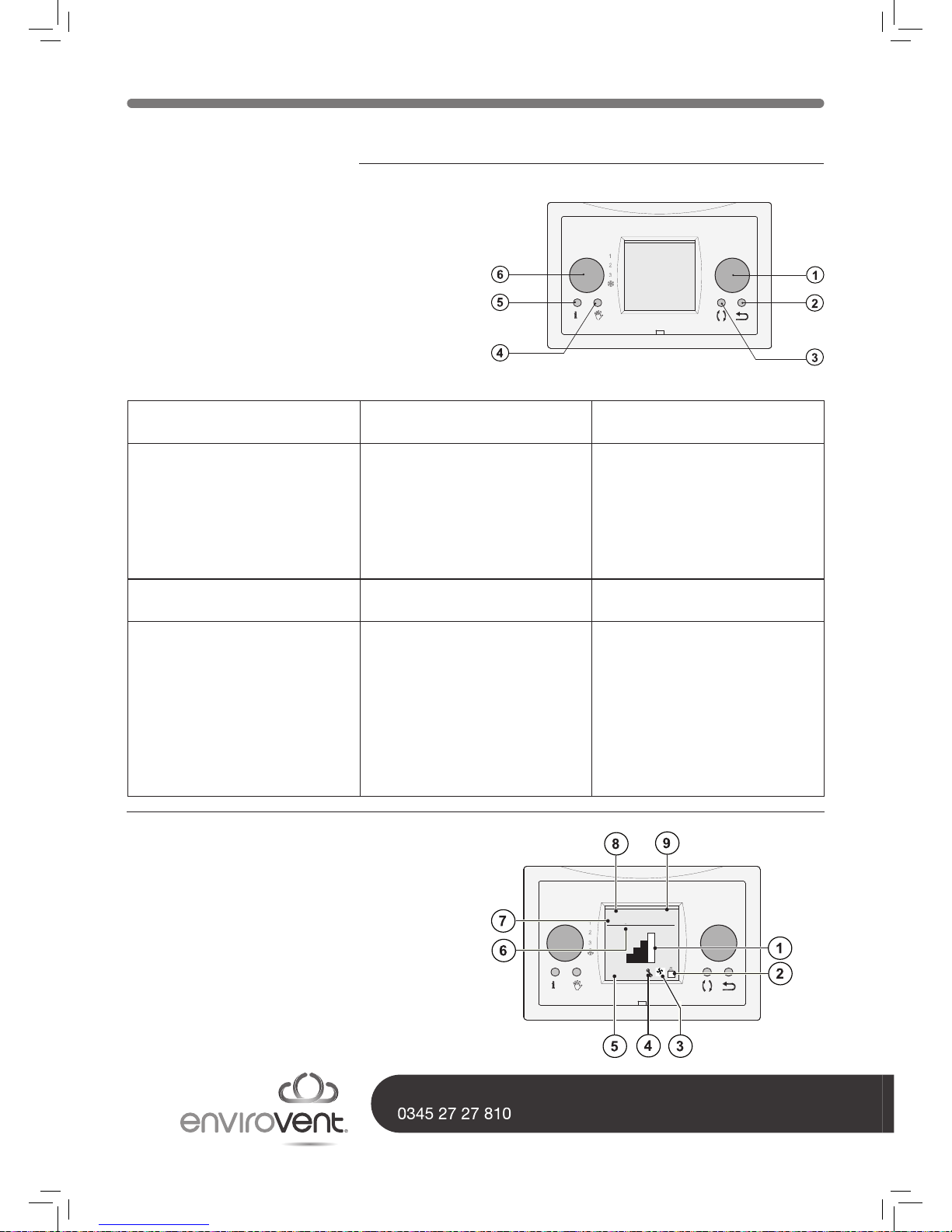
General explanation of control unit
The control unit display shows what the operating
mode of the appliance is. Settings in the control
unit software of the Slimline 150 can be called
up and changed with the aid of the operating
keys. Ex factory the control module is set for the
English language. In the setting menu control
unit, (see page 21) you can choose a language.
View on display
When the Slimline 150 is in operating mode,
the control unit display indicates a number of
dierent values:
08:0 0 23 :00 -
08 :30
23.01.12Sonntag
FILTER
1. Right-hand setting knob 2. Return-key 3. Key appliance selection
Air ow rates can be changed by
rotating the ‘Right-hand setting
knob’. Pressing the ‘Right-hand
setting knob’ takes you to the Main
Menu (Main Menu) of the Slimline
appliance (see page 19).
Press the Return key () to leave
any selected menu/ (temporary)
ventilation mode and the appliance
will return to operating mode.
With the appliance selection key
you can choose to what appliance
the control unit is connected.
4. Key manual control 5. Info-key 6. Left-hand setting knob
After pressing the key manual
control () the operation of the
timer program “overruled. The
display shows on the location of
the actual time block the message
‘manual’. The unit continues to
operate in this manual setting until
it is cancelled by pressing the
‘Return’ key ().
Pressing the ‘Info-key’ () takes
you to the ‘User information menu’
(see page 19).
The left hand button on the control
panel has no function.
08: 00 2 3:00 -
08 :30
23.01.12Sonntag
FILTER
Sunday
Page 19
AFTER INSTALLING THIS UNIT PLEASE PASS ONTO END USER
DO NOT THROW AWAY
18
05 Control Display
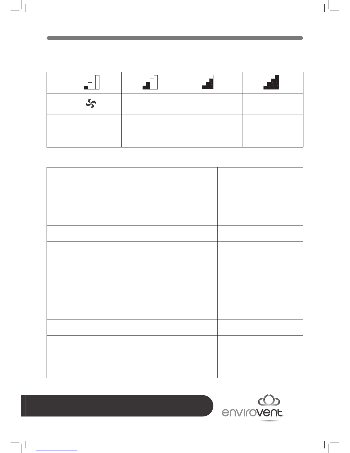
1. Flow rate indicator 2. eBus connection indicator 3. Fan indicator
The display shows a bar chart
(ow rate indicator) of the current
ventilation rate.
This eBus indicator appears when
the eBus connection is active; if it
is not visible, no communication is
possible between the control unit
and the Slimline appliance.
This ventilation indicator appears
when the fans in the appliance are
running.
4. Fault symbol 5. Filter message 6. Current time block
This fault symbol appears when an
appliance fault has occurred.
When the text “Filter” appears on
the control unit display, the lters in
the appliance must be cleaned or
replaced.
This indicates in what
(preprogrammed) time interval the
appliance is. When the manual
control key () is activated, the
time interval picture disappears
and is replaced by the message
“Manual”. When the ventilation ow
rate is modied temporarily using
the right-hand setting knob, the
time interval picture disappears
and is replaced by the message
“Temporary”.
7. Current day 8. Appliance selection
9. Current date (day/month/
year) and time
The current day is shown at this
position.
Pressing the appliance selection
key calls up a menu in which the
appliance can be selected that is
connected to the control unit.
The current date and time are
shown at this position. It is
important for proper performance
of the appliance that the time is set
correctly.
A
B
1 2 3
The supply and extract
fans are running at
30 m3/h or they are
stopped (step 1)
The supply and extract
fans are running in
ventilation mode 1
(step 2)
The supply and extract
fans are running in
ventilation mode 2
(step 3)
The supply and extract
fans are running in
ventilation mode 3
(step 4)
A = Flow rate indicator
B = 4-way switch
Page 20
SHOULD YOU ENCOUNTER ANY PROBLEMS INSTALLING THIS UNIT CALL
19
05 Control Display
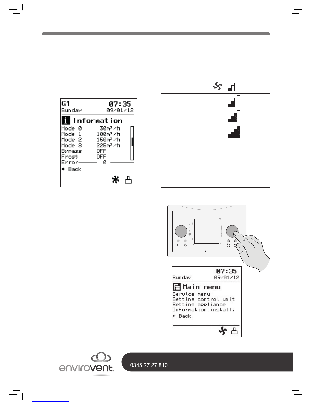
User information menu
Pressing the info key (
) on the control unit calls
up current values. Modifying values or settings
is not possible in this menu.
Readout Value
1 Airow rate 30 m
3
/h
2
Airow rate /
Ventilation mode 1
75 m
3
/h
3
Airow rate /
Ventilation mode 2
100 m
3
/h
4
Airow rate /
Ventilation mode 3
125 m
3
/h
5 Bypass diuser
Open or
Closed
6 Frost protection active
ON or
OFF
7
Most recent fault message (see
page 25 for explanation fault
codes)
Exxx
Main menu
Pressing the right-hand setting knob on the
control unit takes you to the MAIN MENU.
In this main menu you can use the right-hand
setting knob to select one of the 4 available
menus (rotate to select and press to conrm)
including:
• Service menu (Service menu, see page 20)
• Settings menu control unit (Settings control
unit, see page 21)
• Settings menu appliance (Settings appliance,
see page 22)
• Information menu installer (Information install,
see page 23 )
08: 00 2 3:00 -
08 :30
23.01.12Sonntag
FILTER
Page 21
AFTER INSTALLING THIS UNIT PLEASE PASS ONTO END USER
DO NOT THROW AWAY
20
05 Control Display
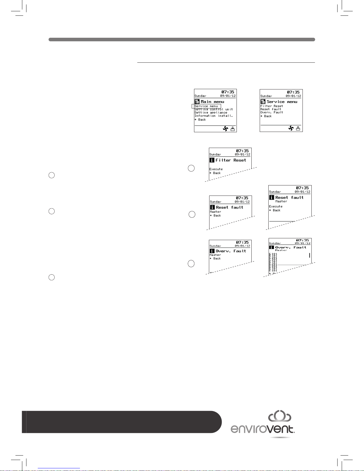
Service menu
From the main menu, rotate the right-hand
setting up to select the SERVICE MENU and
conrm this choice by pressing the right-hand
setting knob.
In the service menu, you can select from three
underlying menus, including:
• Filter reset (Filter Reset)
• Reset fault codes (Reset fault)
• Overview fault codes (Overv. fault)
A
Filter reset (Filter Reset)
When you select lter reset, such a reset will
be carried out for all appliances connected
to the control unit.
B
Reset fault codes (Reset fault)
Activating reset fault codes will delete
the fault codes list for every individual
connected appliance. If only 1 appliance
is connected, then that one is the master
appliance; no more appliances are shown
in this list than are detected through the
eBus connection.
C
Overview fault codes (Overv. fault)
Overview fault codes shows the fault
codes for every appliance (E-code); an
explanation of fault codes is shown on
page 25.
If only 1 appliance is connected, then that
one is the master appliance; no more
appliances are shown in this list than are
detected through the eBus connection.
C
A
B
MAIN MENU SERVICE MENU
Page 22
SHOULD YOU ENCOUNTER ANY PROBLEMS INSTALLING THIS UNIT CALL
21
05 Control Display
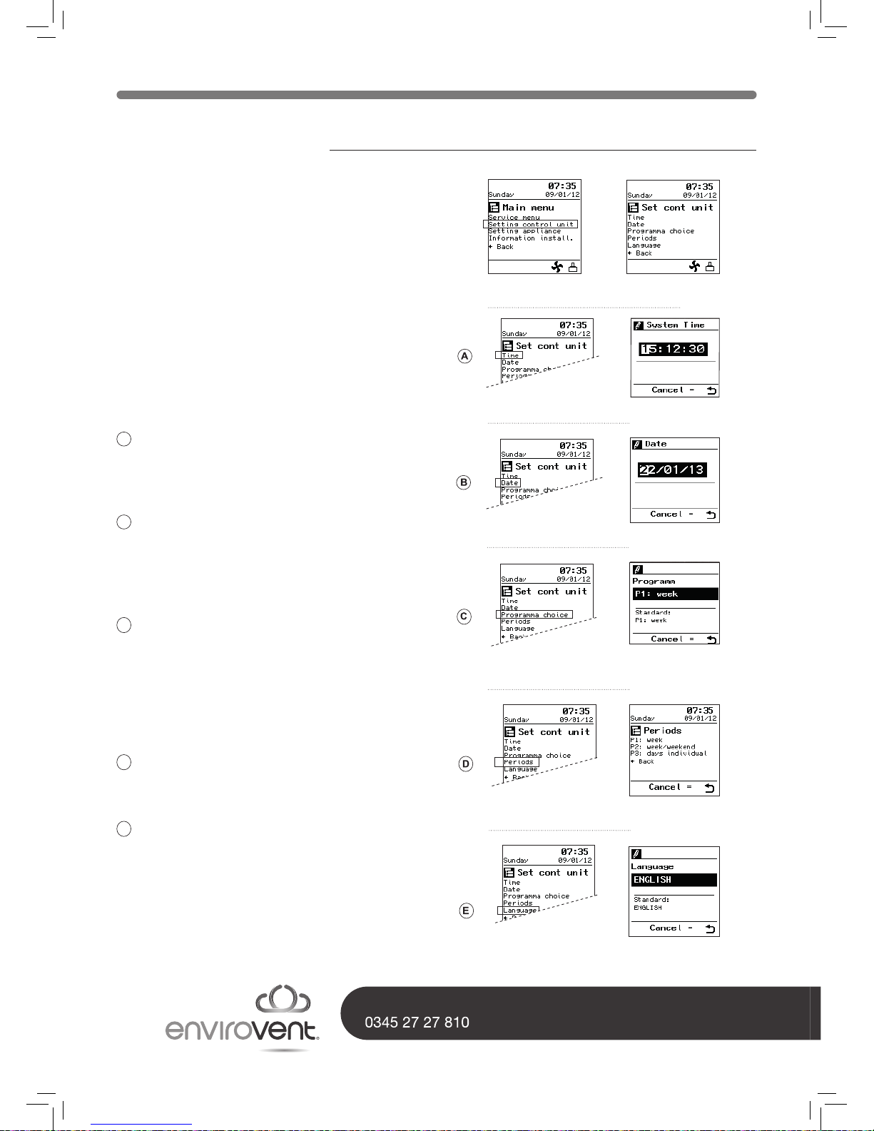
Settings menu control unit
From the main menu, rotate the right-hand
setting up to select the SETTING MENU
CONTROL UNIT (Setting control unit) and
conrm this choice by pressing the right-hand
setting knob. In this menu, you can select from
ve underlying menus, including:
- Time (Time)
- Date (Date)
- Programme choice (Programma choice)
- Programme setting (Periods)
- Language (Language)
A
Time (Time)
The current time must be set in this menu.
The time is always shown in 24 hours
mode.
B
Date (Date)
The current date must be set in this menu;
since a calendar is programmed in the
software, the correct day will automatically
be shown.
C
Programme choice (Programma choice)
In this menu you can choose the active
programme, including:
programme P1 → week programme
programme P2 → week/weekend
programme
programme P3 → day programme
D
Programme setting (Periods)
In this menu you can set/modify the times/
air ow rates for every period.
E
Language (Language)
In this menu you can choose a language;
ex factory the control module is set for the
English language.
MAIN MENU SETTINGS MENU
CONTROL UNIT
TIME
DATE
PROGRAMME CHOICE
LANGUAGE
PROGRAMME SETTING
Page 23
AFTER INSTALLING THIS UNIT PLEASE PASS ONTO END USER
DO NOT THROW AWAY
22
05 Control Display
MAIN MENU SETTINGS MENU
APPLIANCE
SETTING STEP
NUMBERS
A
FACTORY SETTING
B
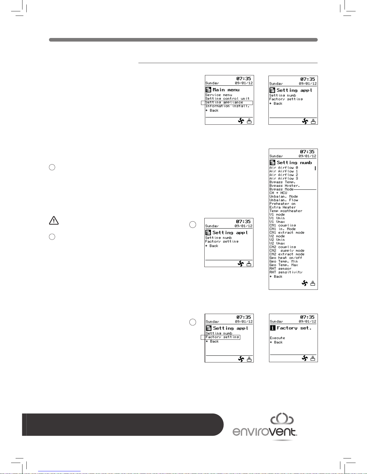
Settings menu appliance
From the main menu, rotate the right-hand
setting knob to select the SETTINGS MENU
APPLIANCE (Setting appliance) and press the
right-hand setting knob to conrm this selection.
In this menu, you can select from two underlying
menus, including:
• Setting step numbers (Setting numb)
• Factory setting (Factory setting)
A
Setting step numbers
Selecting parameter takes you to the
overview of all step numbers of the
appliance as described on pages 39-41. In
this menu you can view these values and, if
necessary, modify them.
Incorrect settings may seriously aect
the proper performance of the appliance
B
Factory setting (Factory setting)
Selecting factory setting will restore all step
numbers to the original factory setting. All
fault messages will be deleted as well.
Page 24
SHOULD YOU ENCOUNTER ANY PROBLEMS INSTALLING THIS UNIT CALL
23
05 Control Display
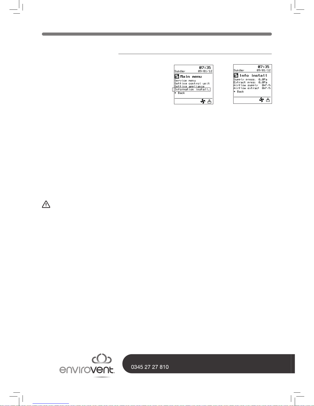
Installer information menu
From the main menu, rotate the right-hand
setting knob to select the INFORMATION
MENU INSTALLER (Information install.) and
conrm this choice by pressing the right-hand
setting knob.
This menu shows seven current values, including:
• Current pressure supply (in Pa) (Supply press.)
• Current pressure extract (in Pa) (Extract press.)
• Current air ow rate supply fan (in m
3
/h.)
(Airow supply)
• Current air ow rate extract fan (in m
3
/h.)
(Airow extract)
• Current temperature dwelling (in °C) (T dwelling)
• Current temperature outside (in °C) (T atmosphere)
• Current relative humidity; only if installed an
RH sensor (in %) (RH)
In this menu you can only read out values,
not modify them.
MAIN MENU INSTALLER
INFORMATION MENU
Page 25
AFTER INSTALLING THIS UNIT PLEASE PASS ONTO END USER
DO NOT THROW AWAY
24
0 8 :30
23/01/12
0 8 :30
23/01/12
0 8 :30
23/01/12
Locking fault
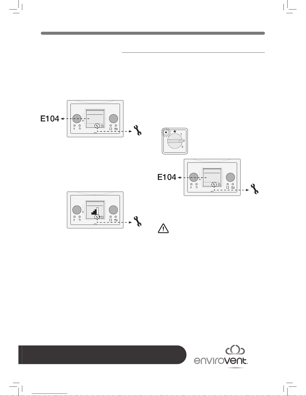
When the appliance detects a non-locking fault,
it will still keep running (limitedly).
The display does show the fault symbol (spanner).
When the appliance control system detects a
fault, it is indicated on the display of the control
unit with a spanner symbol, possibly together
with a fault code.
06 Trouble Shooting
08:0 0 23 :00 -
08:30
23.01.12Sonntag
FILTER
Sunday
08:0 0 2 3:00 -
08:30
23.01.12Sonntag
E104
When the appliance detects a locking fault, it
will no longer work. The (permanently lighted)
display shows the fault symbol (spanner)
together with fault code. The red LED on the
multiple switch (if applicable) will be blinking.
Contact the installer to remedy this fault. A
locking fault cannot be remedied by taking the
voltage from the appliance; rst the fault must
be solved.
08:0 0 2 3:00 -
08:30
23.01.12Sonntag
E104
Sunday
Warning
When working on the appliance,
always remove the voltage from the
appliance by rst switching it o
through software and subsequently
isolating the power.
Sunday
Page 26
SHOULD YOU ENCOUNTER ANY PROBLEMS INSTALLING THIS UNIT CALL
25
06 Trouble Shooting
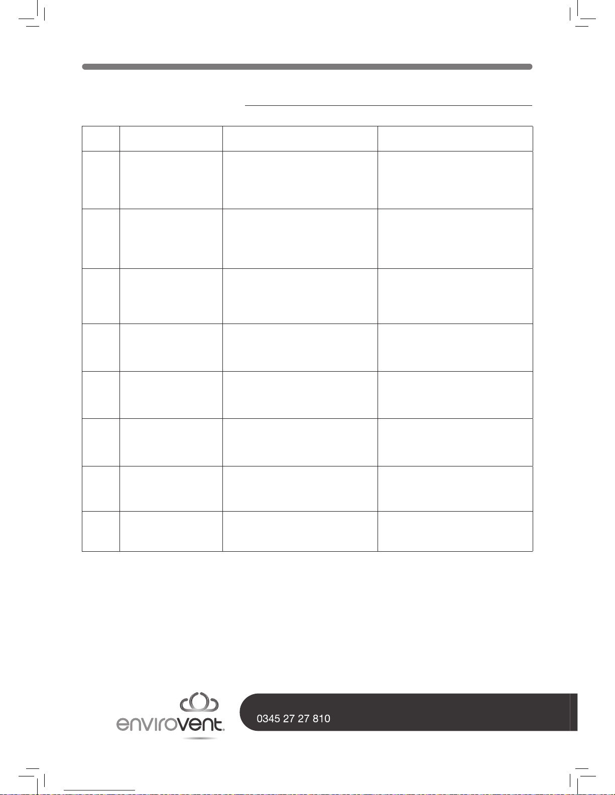
Fault
Code
Cause Action Appliance Action Installer
E103 Bypass fault
• None.
• (Current too low
→
stepper motor
not correctly connected or eective;
current too high → short-circuit
in wiring or stepper motor)
• Disconnect unit from power
• Check connection stepper motor;
replace wiring or stepper motor
E104 Extract fan defective
• Both fans are switched o.
• Preheater is switched o.
• If applicable: Postheater
is switched o.
• Restart every 5 minutes.
• Disconnect unit from power
• Replace extract fan.
• But voltage back on appliance;
Fault will automatically be reset.
• Check cabling.
E105 Supply fan defective
• Both fans are switched o.
• Preheater is switched o.
• If applicable: Postheater
is switched o.
• Restart every 5 minutes.
• Disconnect unit from power
• Replace
• Reconnect unit to power;
Fault will automatically be reset.
• Check cabling.
E106
The temperature sensor
that measures the
outdoor temperature
is defective
• Both fans are switched o.
• Preheater is switched o.
• Bypass closes and is blocked.
• Disconnect unit from power
• Replace temperature sensor
• Put voltage back on appliance;
fault will automatically be reset.
E107
The temperature
sensor that measures
the temperature of the
extract air is defective
• Bypass closes and is blocked.
• Disconnect unit from power
• Replace indoor temperature sensor
E108
If present: The
temperature sensor that
measures the external
temperature is defective
• Postheater is switched o.
• If applicable: Geo heat
exchanger is switched o.
• Replace external
temperature sensor
E111
If present: The RHsensor that measures
the humidity is defective
• Appliance continues to operate
• Disconnect unit from power
• Replace RH-sensor.
Dip switches on control
board not set correctly.
• Appliance does nothing; red
fault LED on multiple switch
is not activated either.
• Put dip switches in correct
position (see page 32).
Note: If mode 2 of a multiple switch does not work, the modular connector of the multiple switch has been connected the
wrong way round. Cut o one of the RJ connectors to the multiple switch and mount a new connector the other way round.
Page 27
AFTER INSTALLING THIS UNIT PLEASE PASS ONTO END USER
DO NOT THROW AWAY
26
07 Maintenance
08: 00 23 :00 -
FILTER
08 :30
23.01.12Sonntag
Sunday
User maintenance
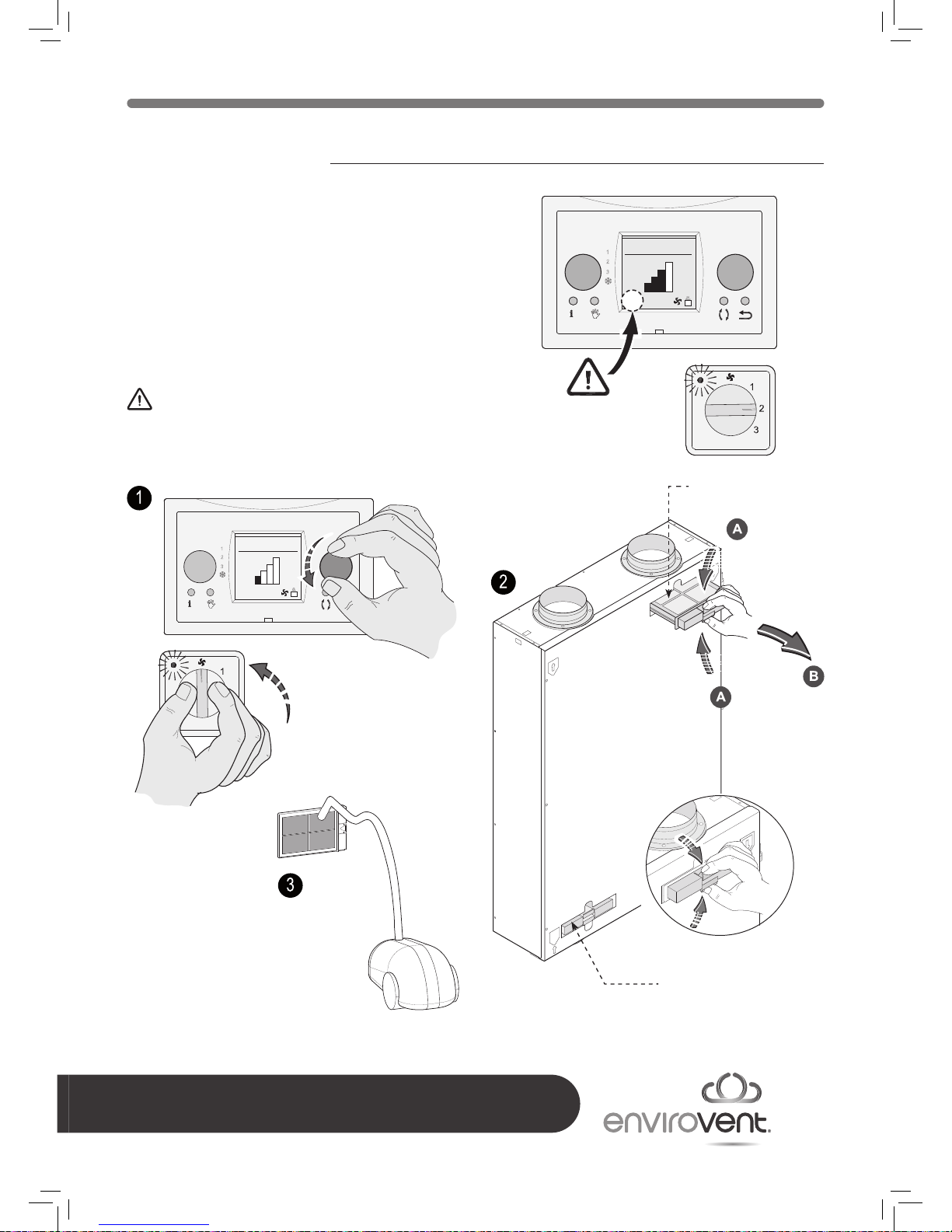
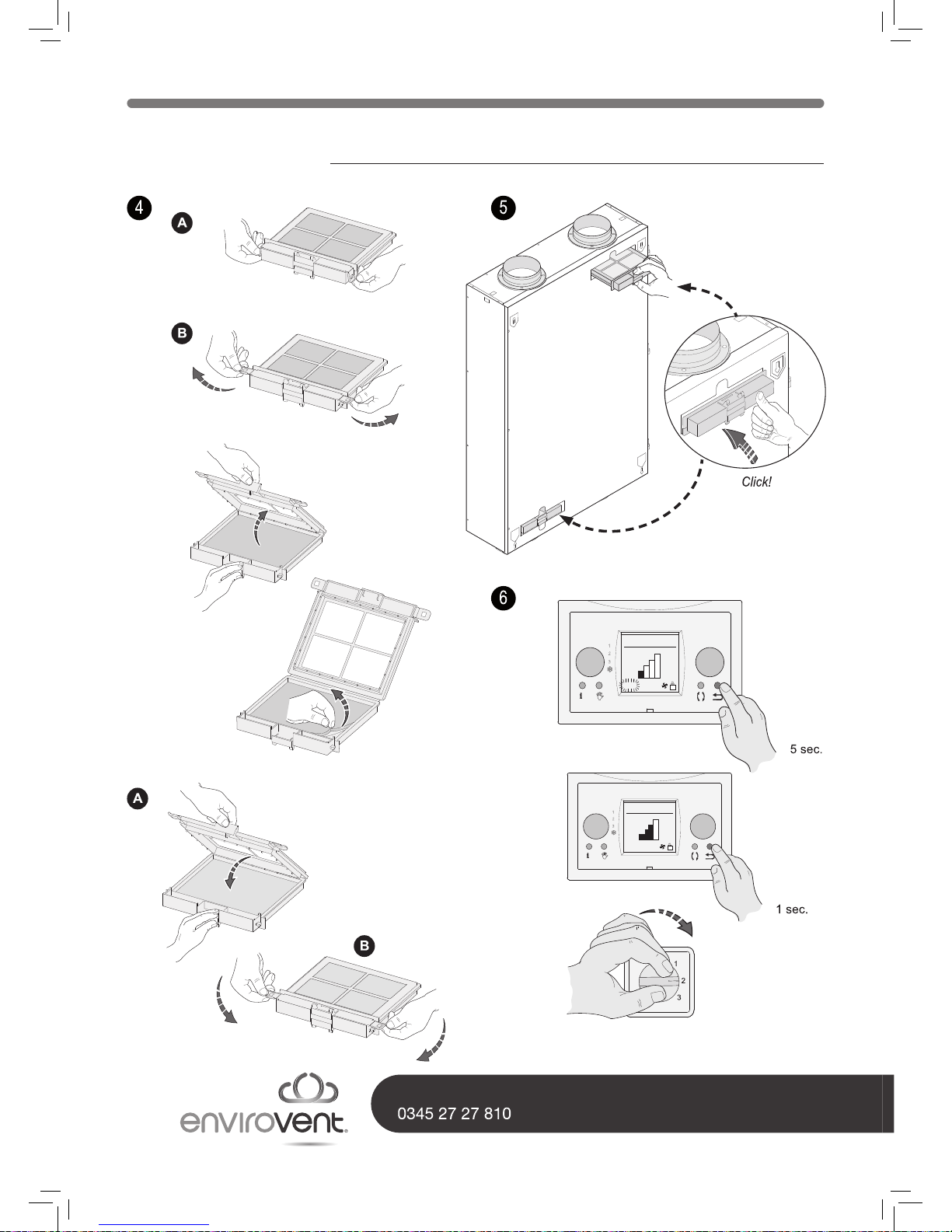
User maintenance is limited to periodically
cleaning or replacing the lters. The lter only
has to be cleaned when that is indicated on
the display (it shows the text “FILTER”) or, if a
multiple switch with lter indication is mounted,
when the red LED at the switch lights up.
The lters must be replaced every year.
It is not permitted to use the appliance
without lters!
Sonntag
08 :30
08:0 0 - 2 3:0 0
23.01.12
FILTER
Sunday
Extract air lter G4
Supply air lter G4 / F7
Page 28
SHOULD YOU ENCOUNTER ANY PROBLEMS INSTALLING THIS UNIT CALL
27
07 Maintenance
Sonntag
08:30
08:0 0 - 2 3:00
23.01.12
Sonntag
08: 30
08:0 0 - 2 3:00
23.01.12
FILTER
Sunday
Sunday
Filter reset
Page 29
AFTER INSTALLING THIS UNIT PLEASE PASS ONTO END USER
DO NOT THROW AWAY
28
B
A
07 Maintenance
Installer maintenance
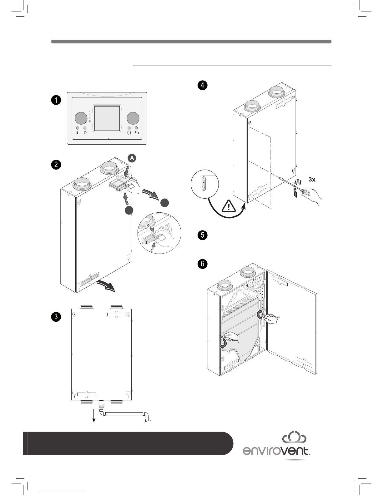
Swing open the front panel (can also be taken
from the hinges, if required).
Isolate power
Page 30
SHOULD YOU ENCOUNTER ANY PROBLEMS INSTALLING THIS UNIT CALL
29
07 Maintenance
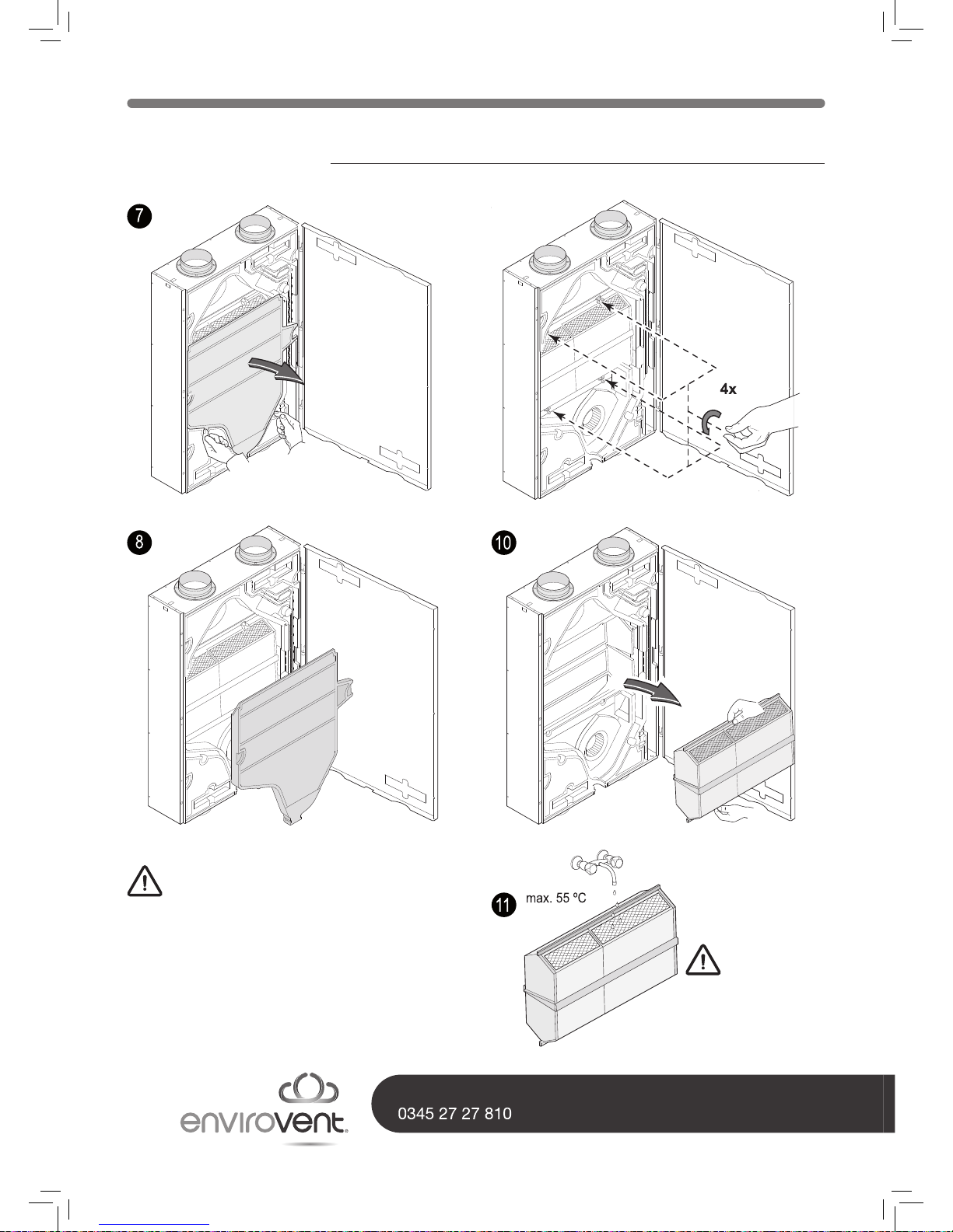
For ceiling mounting, carefully remove the
condensate bin; there may still be some
condensate left in the condensate bin
Rinse the exchanger
with warm water and
a regular detergent.
Page 31
AFTER INSTALLING THIS UNIT PLEASE PASS ONTO END USER
DO NOT THROW AWAY
30
07 Maintenance
Page 32
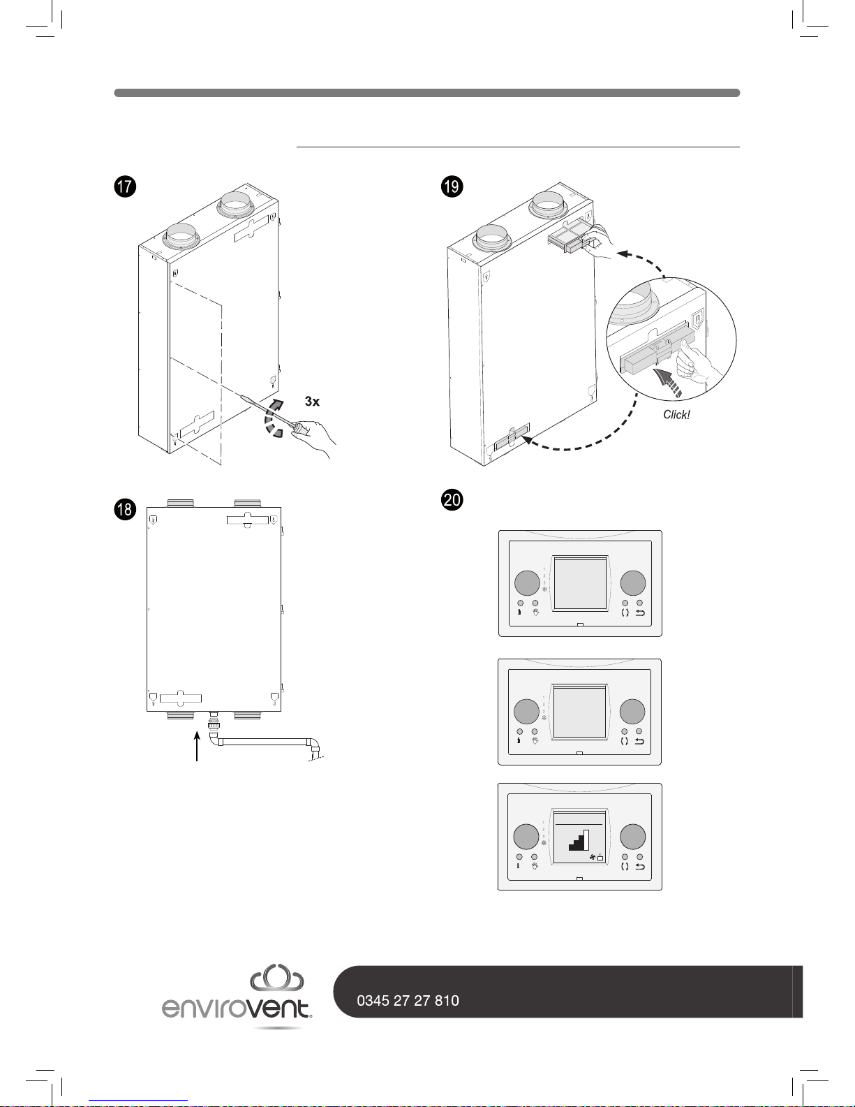
SHOULD YOU ENCOUNTER ANY PROBLEMS INSTALLING THIS UNIT CALL
31
07 Maintenance
Software
S1.03.03
Software
S1.03.03
Connecting
Connecting
08:0 0 2 3:0 0 -
08: 30
23.01.12Sonntag
FILTER
Sunday
Filter reset; (see page 20)
Press the Return key (
) to leave any selected menu
and the appliance will return to operating mode.
Isolate power
Page 33
AFTER INSTALLING THIS UNIT PLEASE PASS ONTO END USER
DO NOT THROW AWAY
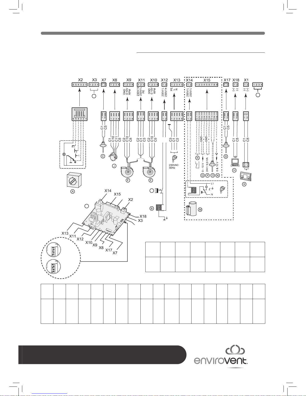
32
L
D
X4
X4
Z
3
X1
C6
C7
T
08 Electric Connections
Slimline
150
Slimline
150 Plus
Only for Plus version
C1 C2 C3 C5 C6 C7 C10 C11
Brown Blue
Green/
yellow
White nr.1 nr.2 Green Yellow
A B C D E F G H J K L M N O P Q R Z
Multiple
switch
Pre-
heater
Outdoor
temp.
sensor
Control
board
Supply
fan
Extract
fan
Indoor
temp.
sensor
Service
connec-
tor
Motor
bypass
valve
Control
unit
Not
applicable
Post-
heater
Output
0-10V
Sensor
post-
heater
24V.
0-10 V
input
External
switch
contact
RH-
sensor
(optional)
Wiring diagram
Page 34
SHOULD YOU ENCOUNTER ANY PROBLEMS INSTALLING THIS UNIT CALL
33
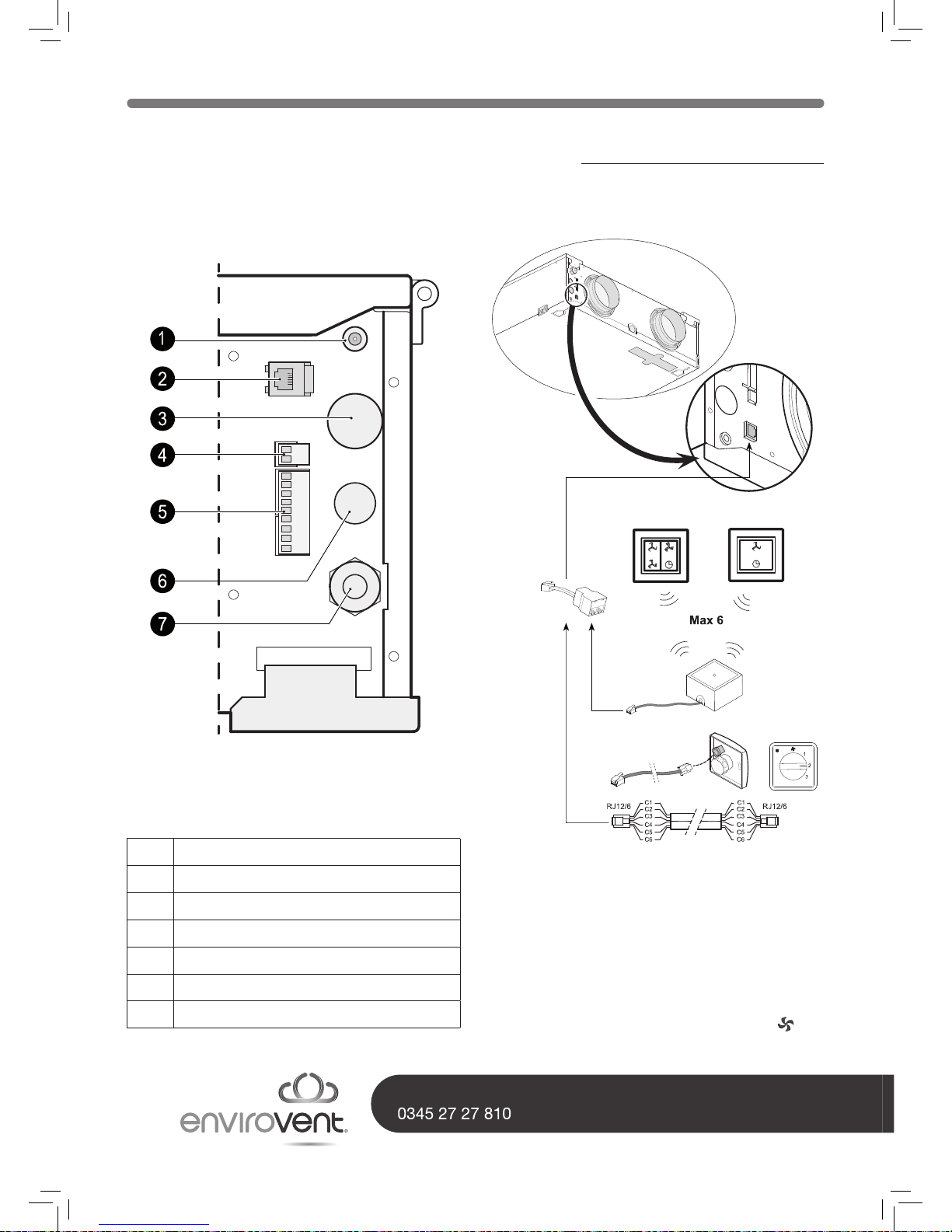
09 Electric Connections Accessories
E2387_4-A.pdf 13-12-2011 15:03:56
E2387_4-A.pdf 13-12-2011 15:03:56
E2387_5-A.pdf 13-12-2011 15:58:41
Note: When several remote controls are used, the
appliance will always run according to the remote
control with the highest set ventilation mode.
The 4-way switch can also be used to activate a
30-minutes boost mode by putting the switch to
setting 3 for less than 2 seconds and directly turning
it back to setting 1 or 2. The boost mode can be reset
by putting the switch to setting 3 for longer than 2
seconds or by switching it to absence mode (
).
Connecting wireless remote control
1
Service connector
2
Modular connector for rpm control
3
Additional cable feed option
4
EBus connector
5
Nine-pole screw connector
6
Cable feed option for postheater
7
Power lead 230V
1 2
3
4
5 6 7
8
9
1
2
Page 35
AFTER INSTALLING THIS UNIT PLEASE PASS ONTO END USER
DO NOT THROW AWAY
34
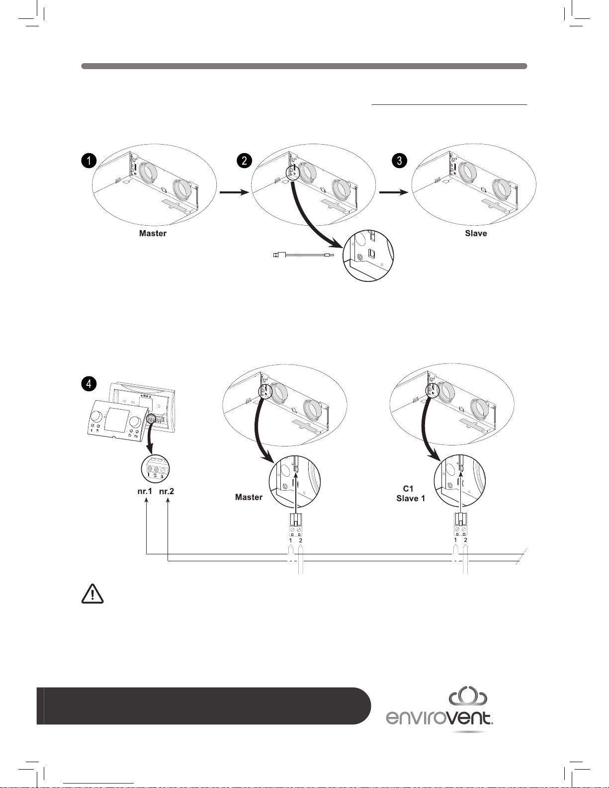
Coupling several Slimline appliances
The slave appliances must be set as slaves
before the appliances are interconnected through
eBus! Refer to the supplied service tool manual
for further instructions. There must be a separate
230V fused spur/isolator for every appliance.
Important:
Because of polarity sensitivity, always
connect contacts X1-1 to X1-1 and
contacts X1-2 to X1-2. Never connect
X1-1 and X1-2. A maximum of 10
appliances (1 Master + 9 Slave max.)
09 Electric Connections Accessories
Page 36
SHOULD YOU ENCOUNTER ANY PROBLEMS INSTALLING THIS UNIT CALL
35
Connection RH (humidity)-sensor
Setting parameter 28 & 29 (see page 41)
Cable sleeve
09 Electric Connections Accessories
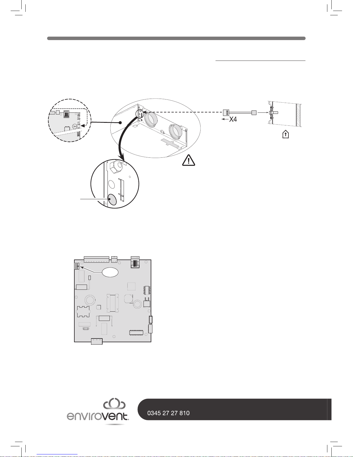
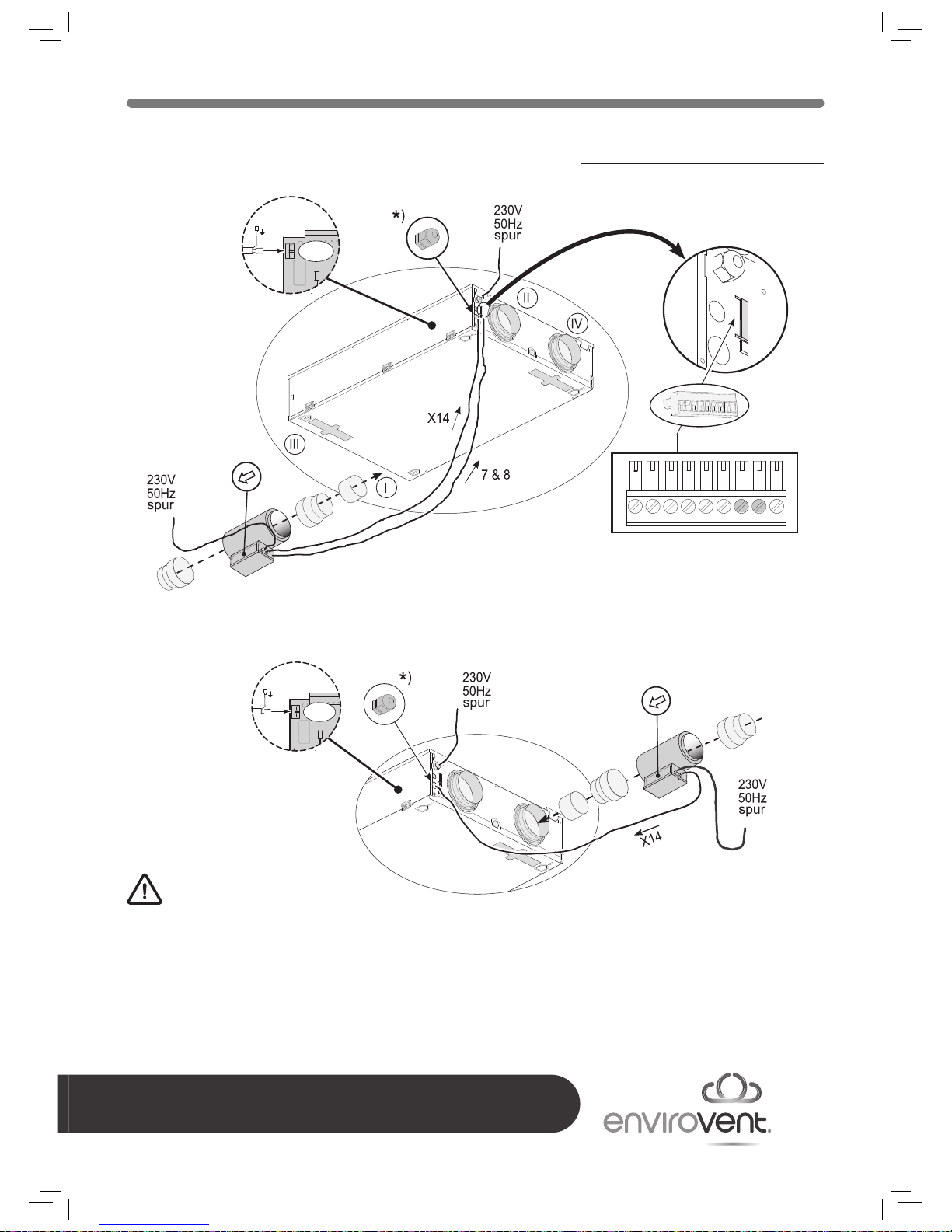
Connection postheater or extra preheater
X14
The postheater or extra preheater (only possible
for Slimline 150 Plus) are electrically connected
to connector X14; just for a postheater there
is also a temperature sensor that must be
connected to no. 7 and 8 of the 9-pole connector
that is only installed in the Plus version.
When using a postheater or extra preheater,
step number 11 is applied (and for extra
preheater also step number 12). Please refer
to the mounting instructions that came with the
heater for more extensive information regarding
installation of the post-heater or the extra
preheater.
Page 37
AFTER INSTALLING THIS UNIT PLEASE PASS ONTO END USER
DO NOT THROW AWAY
36
09 Electric Connections Accessories
The strain reliever to be installed by the installer
(not supplied with the appliance) for feeding
the 230 volt cable to the postheater or extra
preheater.
1
2
3 4
5 6 7 8 9
X14
1
2
3
4
5
6
7
8
9
X14
Setting parameter 11 & 12
(see page 39)
Connection
postheater
Temperature sensor postheater 7 - 8.
Connection
extra preheater
Page 38
SHOULD YOU ENCOUNTER ANY PROBLEMS INSTALLING THIS UNIT CALL
37
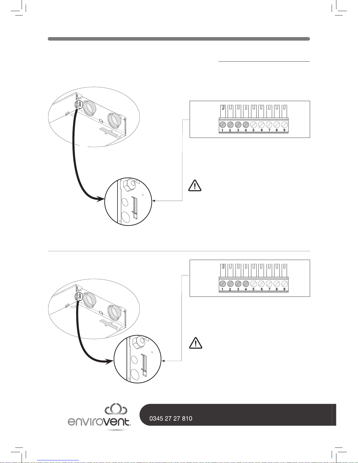
Connecting external switch contact
Connection to 0-10 V input
09 Electric Connections Accessories
Connections no. 1 and no. 2 standard
external switch contact; connections no.
3 and no. 4 can optionally be used as
external switch contact as well.
Setting parameter 16, 17 & 18 (pages
39-40)
An external switch contact (e.g. switch or
relay contact) can be connected to the
Slimline 150 Plus.
If a second input is required as external
switch contact, if necessary connections
no. 3 and no. 4 can be reprogrammed.
Connections no. 3 and no. 4 standard
0-10 volt input; connections no. 1 and
no. 2 can optionally be used as 0-10 volt
input as well..
Setting parameter 19, 20 & 21 (page 40)
The Slimline 150 Plus can be equipped
with an external provision with 0-10 volt
control. Connections X15-3 and X15-4
are set as standard as 0 - 10 V input; it is
activated as standard.
Page 39
AFTER INSTALLING THIS UNIT PLEASE PASS ONTO END USER
DO NOT THROW AWAY
38
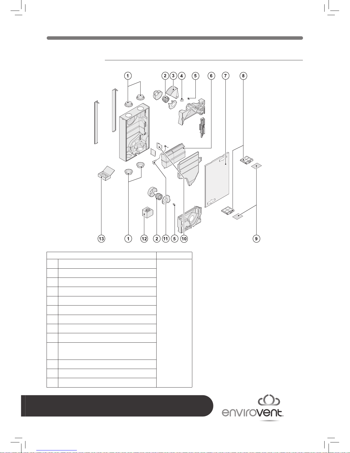
Service parts
10 Servicing
When ordering parts, (see exploded
view), please state the type of the heat
recovery appliance, the serial number,
the year of production and the name of
the part:
N. B.:
Appliance type, serial number and
year of production are stated on the
identication plate on the top of the
appliance.
* When replacing a mains cable, always
order a replacement mains cable from
EnviroVent to avoid danger. A damaged
mains should only be replaced by a
qualied person.
Code
1
Air duct connections (4 pcs)
Please contact
EnviroVent for
order codes
2
Fan (1 pcs)
3
Bypass valve
4
Motor bypass valve
5
Temperature sensor (1 pcs)
6
Heat exchanger
7
Front cover with hinges
8
Filter holder set (2 pieces)
9
Filter kit 2x G4 lter (standard version)
10
Control board (Plus version) When replacing,
note the correct dip switch settings
11
Cable 230V*
12
Heating coil 375 W preheater
13
Control unit
Page 40
SHOULD YOU ENCOUNTER ANY PROBLEMS INSTALLING THIS UNIT CALL
39
11 Setting Values
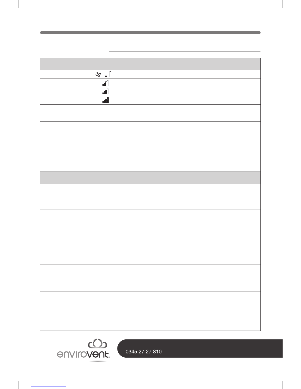
STEP NO. DESCRIPTION
FACTORY SETTING
Slimline 150
ADJUSTING RANGE STEP
1
Air ow rate mode / 30 m3/h 0 m3/h of 30 m3/h
2
Air ow rate mode 1 / 75 m3/h 30 m3/h t/m 300 m3/h 5 m3/h
3
Air ow rate mode 2 / 100 m3/h 30 m3/h t/m 300 m3/h 5 m3/h
4
Air ow rate mode 3 / 125 m3/h 30 m3/h t/m 300 m3/h 5 m3/h
5
Bypass temperature 22,0 °C 15,0 °C - 35,0 °C 0,5 °C
6
Bypass hysterese 2,0 °C 0,0 °C - 5,0 °C 0,5 °C
7
Operation bypass valve 0
0 (= Automatic)
1 (= Bypass valve closed)
2 (= Bypass valve open)
8
Central heating +
heat recovery
OFF
OFF (=Central heating+heat recovery o)
ON (= Central heating+heat recovery on)
9
Imbalance permissible ON
OFF (= ow rate supply equals extract)
ON (= imbalance permissible)
10
Fixed imbalance 0 m3/h -100 m3/h t/m 100 m3/h 1 m3/h
STEP NO. DESCRIPTION
FACTORY SETTING
Slimline 150 Plus
ADJUSTING RANGE STEP
11
Heater 0
0 (= no additional heater)
1 (= additional preheater)
2 (= postheater)
12
Temperature postheater 21,0 °C
15,0 °C t/m 30,0 °C
0,5 °C
13
Selection input 1 0
0 (= normally open contact)
1 (= 0 - 10V input active)
2 (= normally closed contact)
3 (= input 1/ bypas open
→
12V;
bypass closed
→
0V)
4 (= input 1/ bypas open
→
0V;
bypass closed
→
12V)
14
Minimum voltage input 1 0,0 V
0 Volt - 10 Volt 0,5 V
15
Maximum voltage input 1 10,0 V 0 Volt - 10 Vol
t
0,5 V
16
Conditions
switching input 1
0
0 (o)
1 (on)
2 (= On if conditions bypass open satised)
3 (= Bypass control)
4 (= Bedroom valve)
17
Supply fan mode
switching input 1
5
0 (= Input fan o)
1 (= Absolute min. ow rate 30m3/h)
2 (= Flow rate mode 1)
3 (= Flow rate mode 2)
4 (= Flow rate mode 3)
5 (= Multiple switch)
6 (= Maximum ow rate)
7 (= No input fan activation)
Page 41
AFTER INSTALLING THIS UNIT PLEASE PASS ONTO END USER
DO NOT THROW AWAY
40
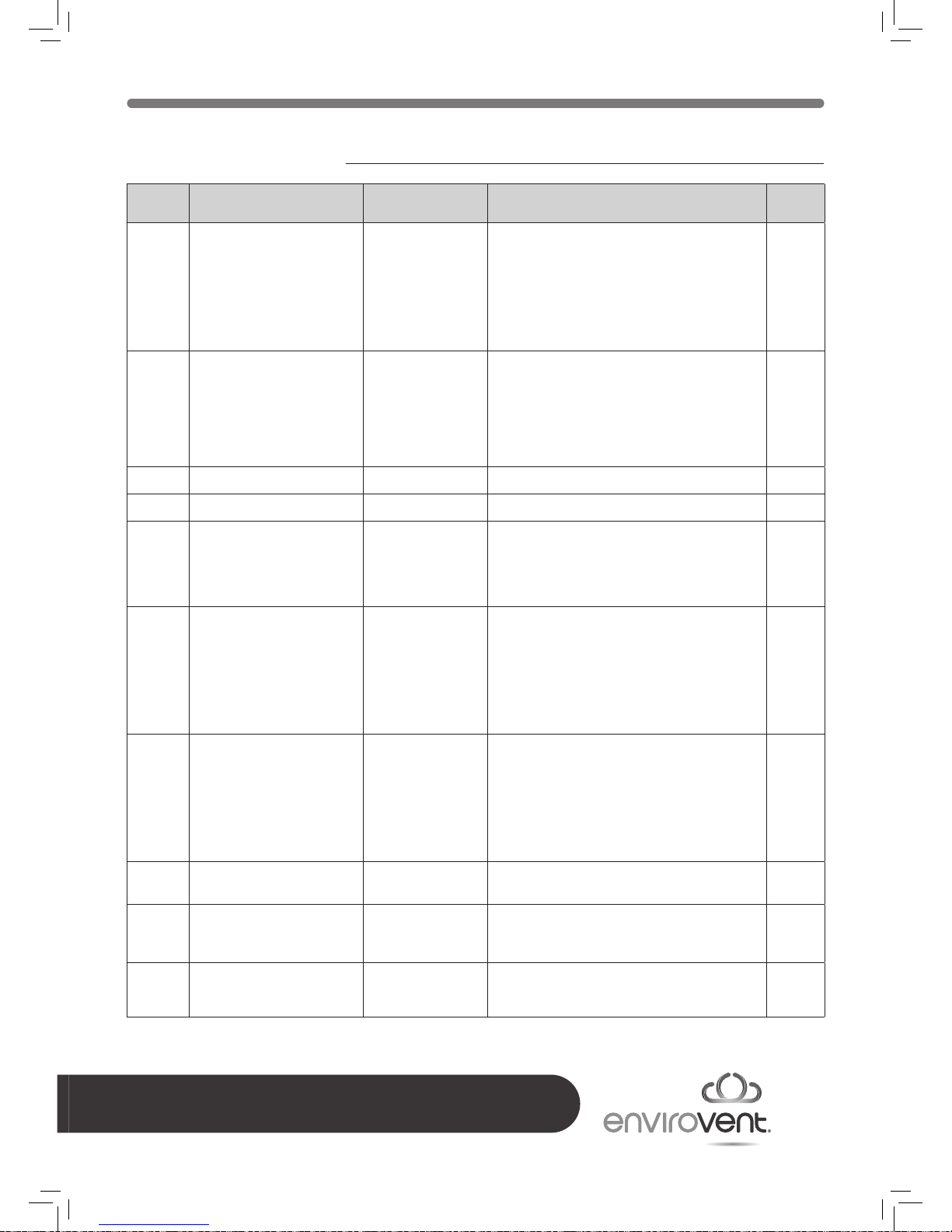
11 Setting Values
STEP NO. DESCRIPTION
FACTORY SETTING
Slimline 150 Plus
ADJUSTING RANGE STEP
18
Extract fan mode
switching input 1
5
0 (= Extract fan o)
1 (= Absolute min. ow rate 30 m
3
/h)
2 (= Flow rate mode 1)
3 (= Flow rate mode 2)
4 (= Flow rate mode 3)
5 (= Multiple switch)
6 (= Maximum ow rate)
7 (= No extract fan activation)
19
Selection input 2 1
0 (= normally open contact)
1 (= 0 - 10V input active)
2 (= normally closed contact)
3 (= input 2/ bypass open
→
12V;
bypass closed
→
0V)
4 (= input 2/ bypass open
→
0V;
bypass closed
→
12V)
20
Minimum voltage input 2 0,0 V 0,0 Volt - 10,0 Volt 0,5 V
21
Maximum voltage input 2 10,0 V 0,0 Volt- 10,0 Volt 0,5 V
22
Conditions
switching input 2
0
0 (o)
1 (on)
2 (= On if conditions bypass open satised)
3 (= Bypass control)
4 (= Bedroom valve)
23
Supply fan mode
switching input 2
5
0 (= Input fan o)
1 (= Absolute min. ow rate 30 m3/h)
2 (= Flow rate mode 1)
3 (= Flow rate mode 2)
4 (= Flow rate mode 3)
5 (= Multiple switch)
6 (= Maximum ow rate)
7 (= No input fan activation)
24
Extract fan mode
switching input 2
5
0 (= Extract fan o)
1 (= Absolute min. ow rate 30m3/h)
2 (= Flow rate mode 1)
3 (= Flow rate mode 2)
4 (= Flow rate mode 3)
5 (= Multiple switch)
6 (= Maximum ow rate)
7 (= No extract fan activation)
25
Geo heat exchanger UIT
OFF (= Valve control geo heat exchanger o)
ON (= Valve control geo heat exchanger on)
26
Minimum temperature geo
heat exchanger (Below this
temperature the valve opens
)
5,0 °C 0,0 °C - 10,0 °C 0,5 °C
27
Maximum temperature geo
heat exchanger (Above this
temperature the valve opens)
25,0 °C
15,0 °C - 40,0 °C
0,5 °C
Page 42
SHOULD YOU ENCOUNTER ANY PROBLEMS INSTALLING THIS UNIT CALL
41
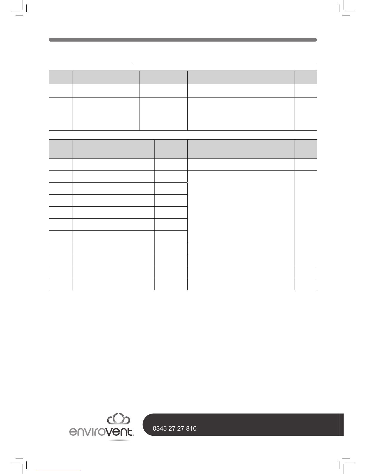
11 Setting Values
STEP NO. DESCRIPTION
FACTORY SETTING
Slimline 150
ADJUSTING RANGE STEP
28 RH-sensor OFF
OFF (= RH-sensor not active)
ON (= RH-sensor active)
29 Sensitivity RH-sensor 0
+2 most sensitive
+1
↑
0 default setting RH-sensor
-1
↓
-2 least sensitive
STEP NO. DESCRIPTION
FACTORY
SETTING
Plus version
ADJUSTING RANGE STEP
35
Switching on and o eBUS CO2 sensor
OFF ON - OFF
36
Min.PPM eBUS CO2 -sensor 1 400
400 - 2000
25
37
Max.PPM eBUS CO2 -sensor 1 1200
38
Min.PPM eBUS CO2 -sensor 2 400
39
Max.PPM eBUS CO2 -sensor 2 1200
40
Min.PPM eBUS CO2 -sensor 3 400
41
Max.PPM eBUS CO2 -sensor 3 1200
42
Min.PPM eBUS CO2 -sensor 4 400
43
Max.PPM eBUS CO2 -sensor 4 1200
44
Flow correction 100% 90% - 110%
45
Default position switch 1 0 - 1
Page 43
AFTER INSTALLING THIS UNIT PLEASE PASS ONTO END USER
DO NOT THROW AWAY
42
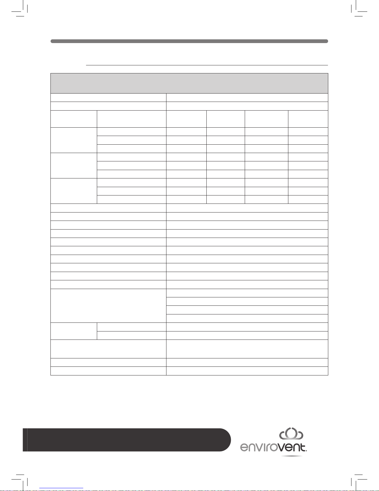
Product data sheet conform Ecodesign (EU), nr. 1254/2014 (Annex IV)
Supplier: EnviroVent
Model: Slimline 150
Climate zone Type of control
SEC-Value
in kWh/m²/a
Energy class (SEC)
The annual electricity
consumption (AEC)
in kWh
The annual heating
saved (AHS)
in kWh
Average
Clock -34,08 A 438 4435
1 Sensor (RH/CO2/VOC) -36,49 A 396 4389
2 or more Sensors (RH/CO
2
/VOC) -40,67 A+ 314 4496
Cold
Clock -76,03 A+ 975 6617
1 Sensor (RH/CO2/VOC) -78,94 A+ 933 6698
2 or more Sensors (RH/CO2/VOC) -84,16 A+ 851 6862
Warm
Clock -10,06 E 393 2282
1 Sensor (RH/CO2/VOC) -12,16 E 351 2310
2 or more Sensors (RH/CO2/VOC) -15,75 E 269 2366
Type of ventilation unit: Ventilation unit with heat recovery
Fan: Variable speed EC fan
Type of heat exchanger: Recuperative plastic cross-counterow heat exchanger
Thermal eciency: 83%
Maximum ow rate: 150 m³/h
Electric power input: 64 W
Sound power level Lwa: 38 dB(A)
Reference ow rate : 105 m³/h
Reference pressure dierence: 50Pa
Specic Power Input (SEL): 0,33 W/m³/h
Control factor:
1,0 in combination with manual switch
0,95 in combination with clock
0,85 in combination with 1 sensor
0,65 in combination with 2 or more sensors
Leakage*:
Internal 0,9%
External
2,3%
Filter warning:
On the display of the ventilation unit / Manual switch / clock control.
Attention! For optimal energy eciency and a proper operation a regular lter
inspection, cleaning or replacement is necessary.
Internet address for Assembly instructions: www.envirovent.com
Bypass: Yes; 100% Bypass
*Measurements executed by TNO according to the EN 13141-7 standard (TNO-report TNO 2014 R10659, April 2014)
12 ErP
Page 44
AFTER INSTALLING THIS FAN PLEASE PASS ONTO END USER - DO NOT THROW AWAY
EnviroVent Ltd
EnviroVent House
Hornbeam Business Park
Harrogate
HG2 8PA
01423 810 810
[email protected]
www.envirovent.com
Due to our policy of continuous innovation and
improvement EnviroVent reserves the right to
alter products specication and appearance
without notice.
E&OE MKT ENV299-V1-01.09.15
615249-A,
manual Slimline 150
 Loading...