

PROFILE-100
Installation and Wiring Instructions

PROFILE-100 AXIAL EXTRACTOR FANS
Suitable for bathroom applications
Thank you for placing your confidence in EnviroVent by buying this product. It
has been manufactured following current technical safety regulations, production
and quality standards as laid down by the international Quality Standard ISO
9001. Please read this instruction booklet carefully before installing or starting up
the product. It contains important information on personal and user safety
measures to be followed whilst installing, using and carrying out maintenance
work on the equipment. Once the product has been installed, please pass this
booklet to the end user.
Check that the product is in perfect condition while unpacking. Any fault or
damage caused in origin is covered by the EnviroVent guarantee. Please make
sure that the product corresponds to the one you have ordered and that the
details on the instruction plate fulfil your requirements.
IMPORTANT:
BE SURE TO HAVE READ AND UNDERSTOOD THESE INSTRUCTIONS
BEFORE BEGINNING THE INSTALLATION PROCESS
SAFETY AND RECOMMENDATIONS
All wiring must comply with Building Regulations and the current I.E.E. Wiring
Regulations (BS7671) or the equivalent standards for your country.
The final installation should be examined and tested by a competent person.
This fan is IP44 rated.
Do not install near sources of heat in excess of 40°C.
Position the fan at the furthest distance from the main source of air
replacement in the room in order to achieve maximum airflow performance.
This appliance is not intended for use by young children or infirm persons
unless they have been adequately supervised by a responsible person to
ensure that they can use the appliance safely. Young children should be
supervised to ensure that they do not play with the appliance.
INSTALLATION: PROFILE –100
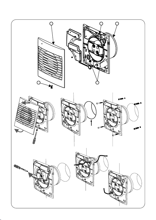
Fig.1
1
3
4
2
5
Ø 105 mm
INSTALLATION: PROFILE –100
Fig.2

Fig.3
Fig.5
Fig.4
N
L
N
L
N
L

Fig.6
Fig.7
Fig.8
+
-
60
90
2
20
% Hr
60/90
% Hr
60/90
t min
2/20
t min
2/20
Fig.9
N
L
N
L

PROFILE-100 AXIAL EXTRACTOR FANS
Suitable for bathroom applications
INSTALLATION
IMPORTANT: before installing and wiring the unit, ensure that the mains supply
is disconnected.
PROFILE-100 should only be used in conjunction with fixed wiring.
Fig.1 1 – Grille
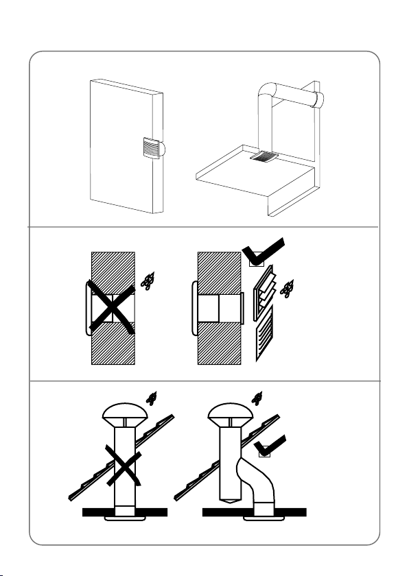
The PROFILE-100 is suitable for panel, ceiling or wall mounting (for wall
mounting applications using EnviroVent wall kit) (fig. 2).
Drill a hole in chosen position in the panel, ceiling or wall of size Ø105mm in
diameter. If the unit is to be installed with ducting, use standard duct size
Ø100mm.
The hole for the duct should be angled downwards to prevent rainwater
running through the duct into the unit.
Loosen the screw (2), which holds the grille in place (1) and remove grille.
Place the extractor against the internal wall or ceiling. For a wall mounted
fan the terminal block should be at the bottom. Mark the 4 screw hole
positions. Drill, plug and screw the extractor in position.
Check that the wall tube is not distorted and that the impeller turns freely.
Once the cable has been introduced through one of the cable points (5), fix
to the wall.
This fan must be installed by a competent person. Complete electrical wiring
of fan as outlined in the Wiring Instructions below. Then refit the grille and
tighten the screw (2).
WIRING
IMPORTANT: ENSURE THAT THE MAINS SUPPLY IS SWITCHED OFF
BEFORE MAKING ELECTRICAL CONNECTIONS.
2 – Fixing screw for front cover
3 – Connection terminals
4 – Outlet
5 – Cable entry point

The PROFILE is an extractor fan designed for a single-phase supply, with
voltage and frequency as indicated on the rating plate of the unit. The units are
manufactured with double insulation (Class ll) and therefore do not require an
earth connection.
• PROFILE – 100 S
This model uses the following wiring diagrams:
Fig.3. Fan operating through a light switch.
Fig.4. Fan operating through an independent switch.
• PROFILE – 100 P
Models fitted with on/off pullcord switch use the following wiring diagrams:
Fig.3. Fan operating through a light switch.
Fig.4. Fan operating through an independent switch or sensor.
• PROFILE – 100 T
Models fitted with adjustable timer.
The timer enables the fan to continue running for the selected period after the
switch has been turned off.
Fig.5. Fan operating through an independent switch.
Fig.6. Fan operating through a light switch.
The desired run-on time is selected by means of an adjuster positioned on the
printed circuit board (Fig.7), and is accessible once the grille (1) is removed.
• To reduce the run-on time, turn anticlockwise (min. 1 minute).
• To increase the run-on time, turn clockwise (max. 30 minutes).
• PROFILE – 100 HT
Models provided with an electronic humidistat, which can be adjusted from 60%
to 90%RH (relative humidity), and with a timer, adjustable between 2 and 20
minutes.
Specific recommendations
- In order to change the settings of the fan you will need to handle the controls
located on the PCB. These adjusters are fragile and must be handled with
care.

- In order to ensure correct measurement of humidity levels, the fan must be
installed in an area where there is good air circulation.
- Ensure that the fan is inside the room that it is to be installed in when setting
the humidity level.
- If the humidity level is consistently above 90%, the fan will continue to run
without stopping.
Operation
Case 1: Automatic operation (Fig.8).
The humidistat causes the extractor to operate automatically when the humidity
level in the room is higher than the set level. The extractor will stop automatically
when the humidity drops below the selected level and after the selected period,
set on the timer.
Case 2: Automatic with manual override.
Automatic operation as in case 1, but with the facility to override the humidistat
by means of the light switch (Fig.6), when the humidity level in the room is lower
than the selected level. In this case, the extractor continues to operate for the
period set on the timer, after the light switch has been switched off.
ATTENTION: When the humidity rises above the selected value, the
automatic option takes precedence over the manual and the unit cannot
then be switched off using a switch.
Settings:
The fans are set to operate at 60% relative humidity and with 2 minutes run-on
time. If the humidity in the room is lower than 60%, the fan will not turn on. If it is
higher, the fan will operate until the humidity level drops below 60%RH and then
runs for the length of time set by the timer. The desired humidity level and time
delay are set by means of adjusters positioned on the printed circuit board (fig. 9)
and accessible once the grille (1) has been removed.
The humidity is set by the adjuster. “% Hr”
- To increase the humidity setting turn anticlockwise (min.60 %)
- To reduce the humidity setting turn clockwise (max. 90 %)
The timer is set by the adjuster “t min.”
- To reduce the run-on time, turn anticlockwise (min. 2 minutes)
- To increase the run -on time, turn clockwise (max: 20 minutes).
ATTENTION: When the fan is operating on run-on time phase, it must finish
before adjusting to a new setting.

Note:
If the fan never turns on:
- Humidity adjuster is not at its lowest setting. Turn the adjuster anticlockwise
(do not force the adjuster) to the minimum setting.
- The fan is fitted in an area where there is no air flow.
- The humidity level in the room is below 60% RH.
If the fan never stops:
- Humidity adjuster is not at its highest setting. Turn the adjuster clockwise (do
not force the adjuster) to the maximum setting.
- The humidity level in the room is above 90% RH.
• PROFILE – 100 PIR
Models provided with a PIR (passive infra-red) detector and a “run on” timer (1 to
30 mins).
The unit starts automatically when a movement is detected within a maximum
distance of 2 metres (fig. 8) and will continue to operate for the set period.
The desired run-on time is selected by means of an adjuster positioned on the
printed circuit board (fig. 7) and accessible once the grille (1) has been removed:
- To reduce the run-on time, turn anticlockwise (min. 1 minute)
- To increase the run-on time, turn clockwise (max: 30 minutes).
CLEANING AND MAINTENANCE
IMPORTANT: DISCONNECT FROM THE MAINS SUPPLY BEFORE
CARRYING OUT CLEANING OR MAINTENANCE
To ensure optimum performance from you extract fan, it should be cleaned
regularly by a competent person.
AFTER SALES SERVICE
We recommend you not to dismantle or remove any other parts than those
mentioned, as any tampering would automatically cancel the guarantee. If you
detect any fault, contact EnviroVent on 01423 810810.
Thank you for choosing EnviroVent - the fastest growing ventilation company in
the UK.
And remember, if you have any problems please call our dedicated Technical
Team on the Hotline 0845 27 27 810.

GUARANTEE
The PROFILE-100 range products are covered by a two year
guarantee, subject to the specified maintenance stated within
this booklet. In the event of any failure of the fan within two
years of supply- excluding only wilful or careless damage – we
will exchange the fan free of charge.
EnviroVent Ltd
EnviroVent House
Hornbeam Business Park
Harrogate
HG2 8PA
Name and address of purchaser ………………………………………
Model ..................................................................................................
Date of purchase …………………………………………………………
Dealer stamp

Ref. 9023007403
EnviroVent Ltd
EnviroVent House
Hornbeam Business Park
www.envirovent.com
Harrogate
Hg2 8PA
01423 810 810
info@envirovent.com
 Loading...