


POWER-170 & 250
Installation and Wiring
Instructions
Installation and Wiring
Instructions


POWER-170 & 250 CENTRIFUGAL EXTRACTOR FANS
Suitable for kitchen applications
Thank you for placing your confidence in EnviroVent by buying this product. It
has been manufactured in accordance with current technical safety regulations,
production and quality standards as laid down by the international Quality
Standard ISO 9001. Please read this instruction booklet carefully before installing
or operating the product. It contains important information on personal and user
safety measures to be followed whilst installing, using and carrying out
maintenance work on the equipment. Once the product has been installed, please
pass this booklet to the end user.
Check that the product is in perfect condition while unpacking. Any fault or
damage caused in origin is covered by the EnviroVent guarantee. Please make
sure that the product corresponds to the one you have ordered and that the
details on the instruction label fulfil your requirements.
IMPORTANT:
BE SURE TO HAVE READ AND UNDERSTOOD THESE INSTRUCTIONS BEFORE
BEGINNING THE INSTALLATION PROCESS
SAFETY AND RECOMMENDATIONS:
SITING A POWER 170 OR 250
All wiring must comply with Building Regulations and the current I.E.E. Wiring
Regulations (BS7671) or the equivalent standards for your country. The final
installation should be examined and tested by a competent person.
Do not install near sources of heat in excess of 40°C.
Do not site fan near obstacles which can obstruct airflow.
Position away from any source of water spray. Do not site in a shower enclosure.
Ducted Applications. In circumstances where an excessive amount of moisture is
present in the air, then a condensation trap will need to be installed in the exhaust
duct. Horizontal ducts should fall away from the fan unit. Ducts passing
through an unheated roof void should be insulated.
POWER-250 HP & POWER-170 HP. These fans are fitted with automatic
electronic humidity sensors. They should ideally be mounted on an inside wall
between the major moisture source and the door to the other rooms of the building.
Do not site closer than 100mm to cupboards, etc. Do not site above a radiator or
other heat source. We recommend the HP models are mounted as shown in Fig.
2.1.

INSTALLATION: POWER
–
170 & 250
Fig. 1
Fig. 3
Fig. 3
Fig. 2
Fig. 4
Fig. 5
Fig. 6
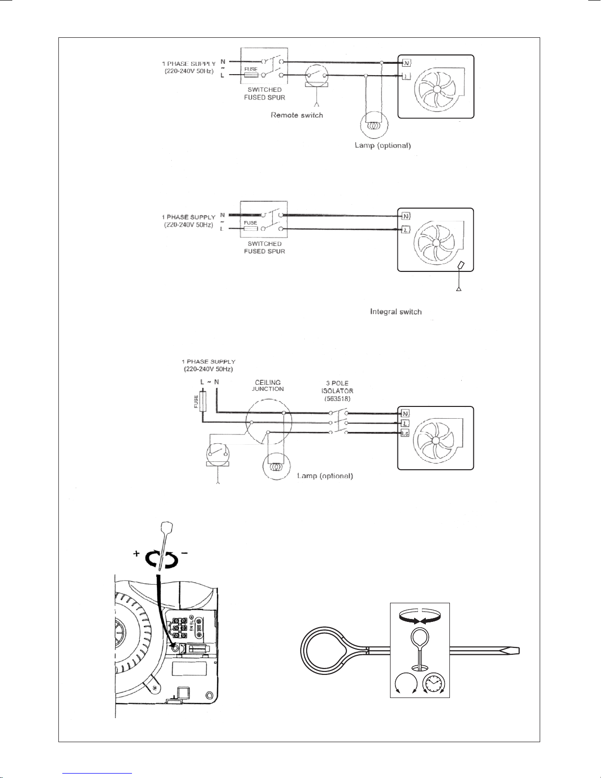
Fig. 7
FAN
Fig. 8
Fig. 9
FAN
FAN
Fig. 10
%RH
%RH
ref.9019012300
ref.9019012300

POWER-170 & 250 CENTRIFUGAL EXTRACTOR FANS
Suitable for kitchen applications
DESCRIPTION
Suitable for both ceiling and wall installation, the POWER fans may be adapted to an
individual duct or to a communal ventilation system (Fig. 1).
The discharge port, situated at the side on the back of the extractor housing, enables it
to be installed anywhere on the wall or ceiling, even in inaccessible corners (Figs.2 & 3).
NOTE: Pullcord models DP and HP should be mounted as shown in Fig.2.1 If NOT
mounted as Fig.2.1, a support (not supplied ) must guide the pullcord so that it does not
rub the fan body. The pullcord (if used) MUST be easy to operate.
INSTALLATION
IMPORTANT: ENSURE THAT THE MAINS SUPPLY IS SWITCHED OFF BEFORE
MAKING ELECTRICAL CONNECTIONS.
- Making use of the template enclosed, make a 100mm diameter round hole in the wall or
ceiling.
NOTE: A 115mm dia. hole is required if a wall sleeve is utilised.
- Drill the holes for the screws and insert the respective plugs in them. Take the extractor fan
and withdraw the grille by pressing on the shoulders at the bottom (Fig.4).
- Remove retaining screw and lift off the terminal box cover (Fig.5).
-The installation may be made with the cable flush fitted by piercing either of the two notches
provided for this (Fig.6.1), or else with surface wiring, using the side cable inlet (Fig.6.2).
- Insert some 150mm of cable into the extractor housing and pass it through the cable
clamp.
- Fix the extractor to the wall. Arrange the foam rubber provided, around the discharge port
so that it fits closely to the duct. Secure the extractor housing to the wall by inserting and
tightening its screws.
WIRING
WARNING: This fan MUST NOT be earthed. It is double insulated. This fan MUST be
connected to a 220-240V 50Hz AC single phase mains supply.
There must be a double pole isolator in the installation with a contact separation of at least
3mm.
Connections depend upon the model of POWER fan being installed and the required mode
of operation.
Ensure that the mains supply is SWITCHED OFF before starting any wiring.

POWER 170 S AND 250 S
Single speed fan. Controlled by remote switch (e.g. light switch or Auto -Sensor), Fig.7.
The neon indicator is lit when the fan is running.
POWER 170 P2S AND 250 P2S
Dual speed and OFF. Low speed running for permanent “trickle” ventilation / High speed
override / OFF, controlled by integral pullcord switch, Fig.8. Pullcord switch sequence –
OFF, LOW, HIGH. The neon indicator is lit when the fan is running.
The POWER 250 P2S only, may alternatively be connected for remote switching. The
remote switch (e.g. light switch) will switch between permanent LOW speed “trickle”
ventilation an HIGH speed override. There is no OFF position with remote switching. Use
Fig.9 for wiring to a remote switch, when the integral pullcord switch must be set for LOW
speed and the pullcord cut off close to the fan.
POWER 170 HP AND 170HP
The fan contains an integral humidity sensor. In automatic mode the control switches the
fan on at LOW speed when the room Relative Humidity (RH) reaches the set-point. The
fan will continue to run until the room RH falls below the set-point. To prevent night time
tripping the humidity sensing is inactive below 10ºC.
The integral pullcord or a remote switch (e.g. light switch) will switch between automatic
humidity control and manual override at HIGH speed. The Light Emitting Diode (LED)
indicator will be lit for manual override. The LED will NOT light under automatic humidity
control, even if the fan is running. There is no permanent OFF position.
Use Fig.8 for wiring the manual override by the integral pullcord. Use Fig.9 for wiring the
manual override to a remote switch, when the pullcord must be switched to the automatic
position (LED off) and the cord cut off close to the fan.
The humidity control is factory set to switch on at about 72% RH.
To LOWER the set-point use a small screwdriver to turn the adjuster ANTI-CLOCKWISE,
Fig.10. This makes the controller MORE sensitive to RH, i.e. it will come on at a lower
RH.
To RAISE the set -point use a small screwdriver to turn the adjuster CLOCKWISE, Fig 10.
This makes the controller LESS sensitive to RH, i.e. it will come on at a higher RH.
NOTES: 1. Upon installation it is possible that the humidity control will make the fan run
continuously until it has acclimatized to the environment.
2. The fan uses a „soft start feature i.e. the motor will take several seconds to
reach speed.
POWER 170 T AND 250 T
Single speed with overrun timer. The fan must be wired to a remote switch (e.g. light
switch),Fig.9. When switched “ON”, the fan will operate at full speed, and will continue to
run for a pre-set time after the switch is turned “OFF”. The timer is factory set at 20
minutes. To reduce the operating time, turn the adjuster in an anti -clockwise direction,
Fig.10. The neon indicator is lit when the fan is running.
After wiring is completed, replace terminal block cover and grille. Turn on mains
supply and check operation.

N.B. If used in a lighting circuit, for reliable operation, we recommend a
tungsten filament lamp. The manufacturers of some fluorescent and low energy
lighting systems indicate that these can interfere with electronic timer circuits.
CLEANING AND MAINTENANCE
IMPORTANT: DISCONNECT FROM THE MAINS SUPPLY BEFORE CARRYING
OUT CLEANING OR MAINTENANCE
The POWER fans have a safety switch which automatically isolates the fan motor
when the outer grille is removed. In this way, the fan may be cleaned without any risk
of electric shocks.
For cleaning purposes, remove the outer grille (Fig.4) and, if your model is a POWER
250, take out the filter at the back of it as well. The filter and the grille may be cleaned
by hand in hot soapy water and the extractor housing wiped with a damp cloth.
We recommend you do not try to remove any more parts than those mentioned as any
tampering would automatically cancel the guarantee.
All regulations and requirements MUST be strictly followed to prevent hazards to life and property
both during and after installation, and during any subsequent servicing and maintenance.
AFTER SALES SERVICE
We recommend you not to dismantle or remove any other parts than those mentioned,
as any tampering would automatically cancel the guarantee. If you detect any fault,
contact EnviroVent on 01423 810810.
Thank you for choosing EnviroVent - the fastest growing ventilation company in the
UK.
And remember, if you have any problems please call our dedicated Technical Team on
the Hotline 0845 27 27 810.
All EnviroVent products are designed to be recycled when they reach the end of their
working life. To save the environment and to reduce landfill, please call EnviroVent on
0845 27 27 810 to arrange for the fan to be returned to the factory.
EnviroVent Ltd
EnviroVent House
Hornbeam Business Park
Harrogate
HG2 8PA

GUARANTEE
The POWER range products are covered by a two year guarantee,
subject to the specified maintenance stated within this booklet. In the
event of any failure of the fan within two years of supply- excluding
only wilful or careless damage – we will exchange the fan free of
charge.
EnviroVent Ltd
EnviroVent House
Hornbeam Business Park
Harrogate
HG2 8PA
Name and address of purchaser ………………………………………………...
Model ……………………………………………………………………………….
Date of purchase ………………………………………………………………….
Dealer stamp


EnviroVent Ltd
Harrogate
Hg2 8PA
01423 810 810
info@envirovent.com
Ref. 9023007701
 Loading...