

Envirovent energiSava 300, energiSava 400 Installation Manual

01 Safety Instructions
IMPORTANT
Be sure to have read and understood these
instructions before beginning the installation
process.
PRE-INSTALLATION CHECK LIST
Make sure that the unit can physically t in to
the desired location.
SAFETY AND RECOMMENDATIONS
• This appliance can be used by children
aged from 8 years and above and
persons with reduced physical, sensory or
mental capabilities or lack of experience
and knowledge if they have been given
supervision or instruction concerning
use of the appliance in a safe way and
understand the hazards involved. Children
shall not play with the appliance. Cleaning
and user maintenance shall not be made
by children without supervision.
Installation must take place under:
• Quality requirements ventilation systems
in dwellings.
• Quality requirements balanced ventilation
in dwellings.
• The regulations for ventilation of dwellings
and residential buildings.
• The safety regulations for low-voltage
installations.
• The regulations for connection to interior
sewers in dwellings and residential
buildings.
• Any additional regulations of the local
utilities.
• The installation instructions for the
energiSava 300 & 400
01
SHOULD YOU ENCOUNTER ANY PROBLEMS INSTALLING THIS UNIT CALL
02 Technical Specications
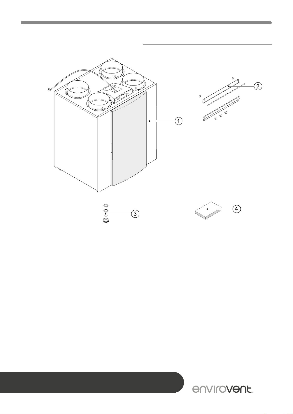
Before you begin to install the heat recovery unit, check that it has been supplied complete
and undamaged.
The energiSava 300 & 400 units should include the following components:
1. Heat recovery appliance type energiSava
300 & 400
2. Wall mounting bracket kit containing:
• 2 x suspension strips
• 3x protective caps
• 1 x rubber strip
• 2 x rubber rings
• 1 x mounting instructions
AFTER INSTALLING THIS UNIT PLEASE PASS ONTO END USER
DO NOT THROW AWAY
3. PVC condensate discharge connection
containing:
• 1 x synthetic screw gland 1.5”
• 1 x sealing ring
• 1 x PVC glued coupling 32 mm
4. Documentation set consisting:
• 1 x installation instructions
02

02 Technical Specications
The energiSava 300 & 400 are ventilation
units with heat recovery incorporating a high
eciency heat exchange cell, a maximum
3
ventilation capacity of 300 or 400 m
low-energy fans.
Features:
• Steplessly adjustable air ow rates through
a control panel;
• Filter indication on the appliance and
the possibility for lter indication on the
multiple switch;
• A completely new intelligent frost
protection system. This ensures that
even at low outdoor temperatures the
appliance's performance remains optimal
and that, if necessary, it activates the
standard preheater.
/h and
Compared to the standard version, the Plus
version has a more extensive control board
which increases the connection options.
These installation instructions describe both
the standard and the Plus versions.
The Plus version is available in the lefthanded or right-handed version. A left-
handed version has the lters on the left
behind the lter door; a right-handed version
has the lters on the right behind the ltered
door. The position of the air ducts diers for
these two versions. For the correct position
of the connection ducts and dimensions
(see pages 9-10).
When ordering an appliance always state
the correct type; subsequent conversion to
a dierent version is not possible.
• Low sound level
• Comes as standard with automatic bypass
valve
• Constant ow control
• Low energy consumption
• High eciency
The energiSava 300 & 400 are available in
two types:
• Standard version
• Plus version
The energiSava 300 & 400 comes ready
to wire into the 230V mains fuse spur and
has a connection for a low-voltage multiple
switch on the outside of the appliance.
03
SHOULD YOU ENCOUNTER ANY PROBLEMS INSTALLING THIS UNIT CALL
02 Technical Specications
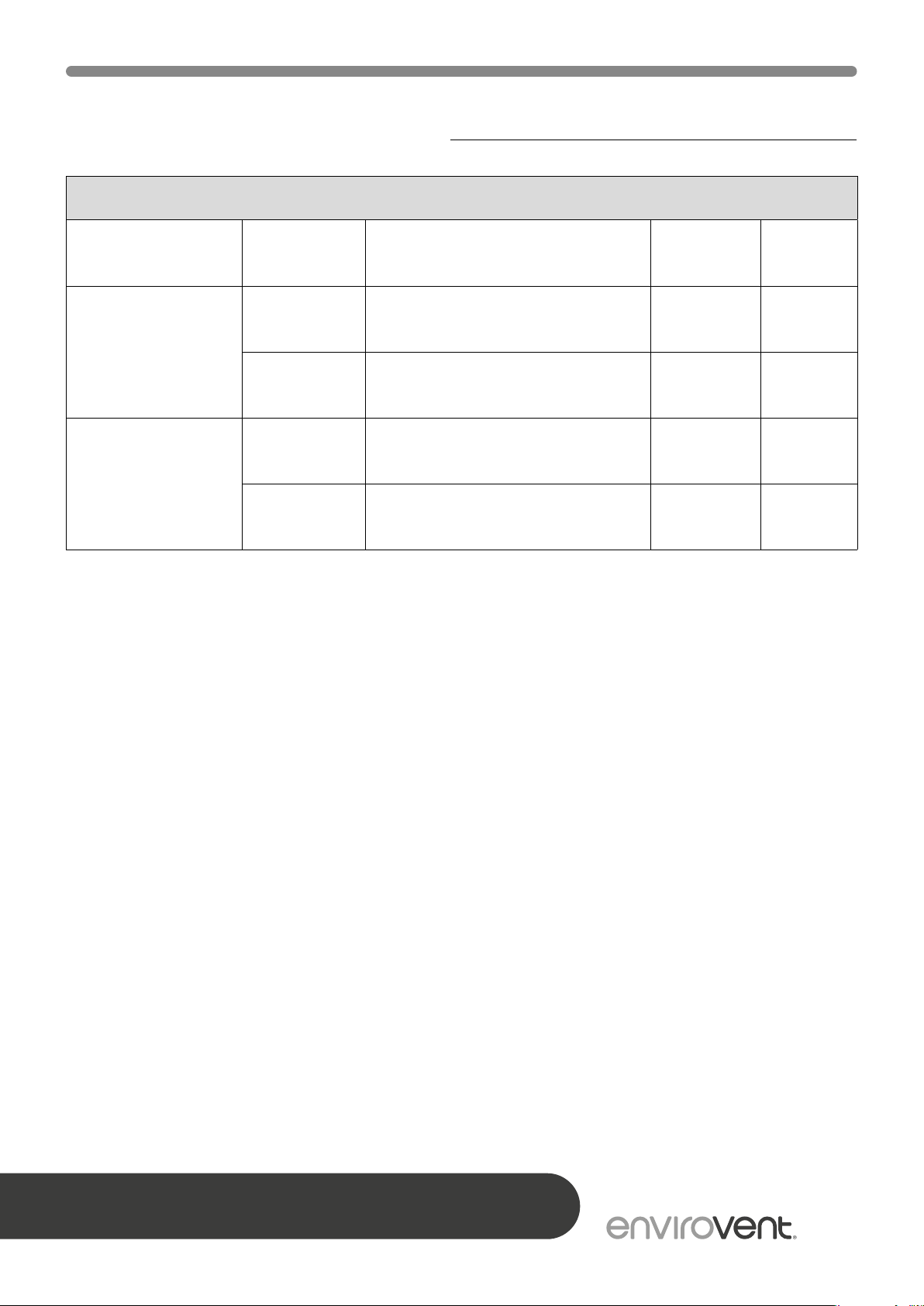
Version types energiSava 300 & 400
Type Version L or R Position air ducts
energiSava
300 & 400
(standard version)
energiSava
300 & 400
(Plus version)
Left-handed
version
Right-hand
version
Left-handed
version
Right-hand
version
4 top connections Power cable 4/0 L
4 top connections Power cable 4/0 R
4 top connections Power cable 4/0 L+
4 top connections Power cable 4/0 R+
Power
supply
Type code
AFTER INSTALLING THIS UNIT PLEASE PASS ONTO END USER
DO NOT THROW AWAY
04
02 Technical Specications
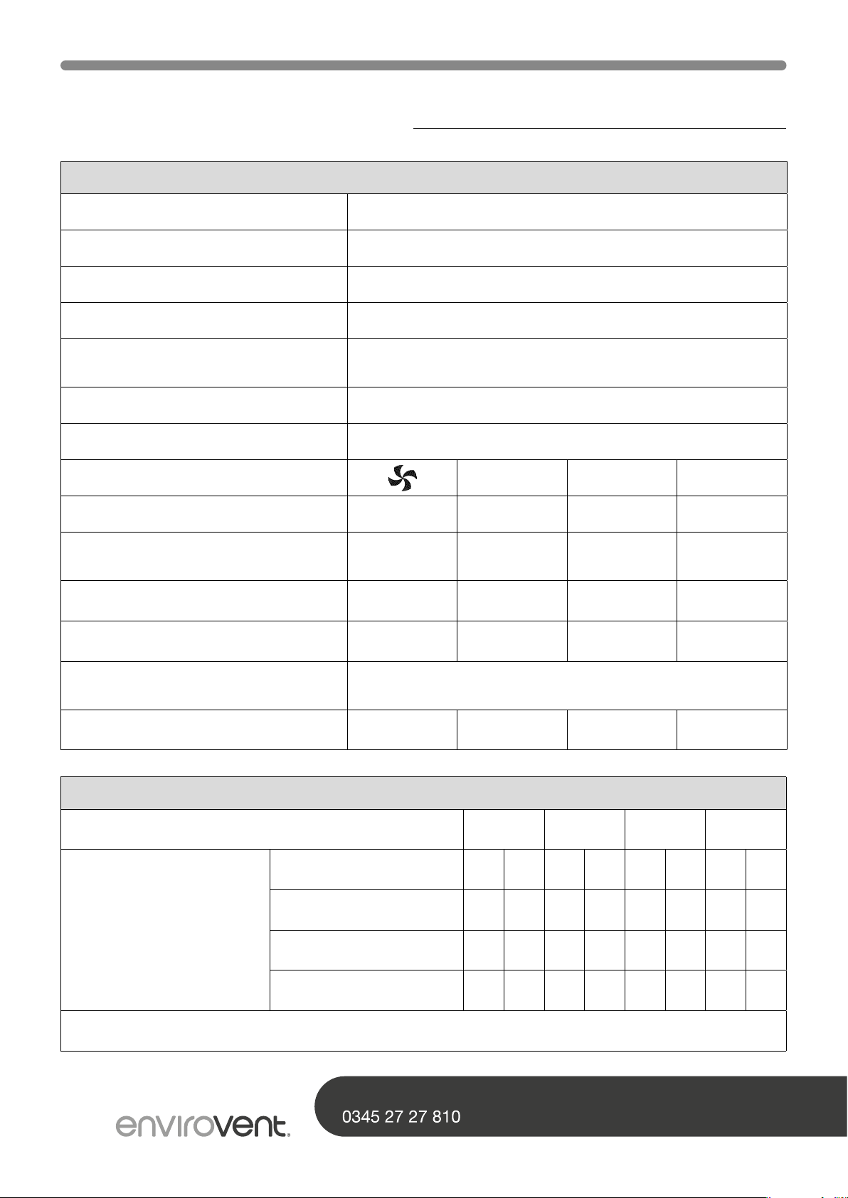
energiSava 300
Supply voltage (V/Hz) 230/50
Protection degree IP30
Dimensions (w x h x d) (mm) 677 x 765 x 564
Duct diameter (mm) Ø160 / Ø150
External diameter condensate
discharge (mm)
Weight (kg) 38
Filter class G3 (F7 optional for supply)
Fan setting (factory setting) 1 2 3
Ventilation capacity (m
Permissible resistance ducts
system (Pa)
Rated power (excl. preheater) (W) 9.0 - 9.2 13.7 - 15.2 22.0 - 29.2 46.8 - 66.2
Rated current (excl. preheater) (AA) 0.104 - 0.107 0.150 - 0.161 0.214 - 0.274 0.403 - 0.578
Max. rated current (with preheater
switched on) (A)
Cos φ 0.368 - 0.374 0.391 - 0.416 0.447 - 0.463 0.505
3
/h) 50 100 150 225
3 - 7 11 - 28 26 - 66 56 - 142
Ø32
6
Sound Power energiSava 300
3
Ventilation capacity (m
Sound power level Lw
(A)
In practice, the value may deviate 1 dB(A) as a result of measuring tolerances
/h) 90 150 210 300
Static pressure (Pa) 50 100 50 100 50 100 50 100
Housing emission dB(A) 30 33 38 38 44 46 50 52
Duct from dwelling dB(A) 33 34 39 42 45 46 54 54
Duct to dwelling dB(A) 44 47 52 55 60 60 67 67
SHOULD YOU ENCOUNTER ANY PROBLEMS INSTALLING THIS UNIT CALL
05
02 Technical Specications
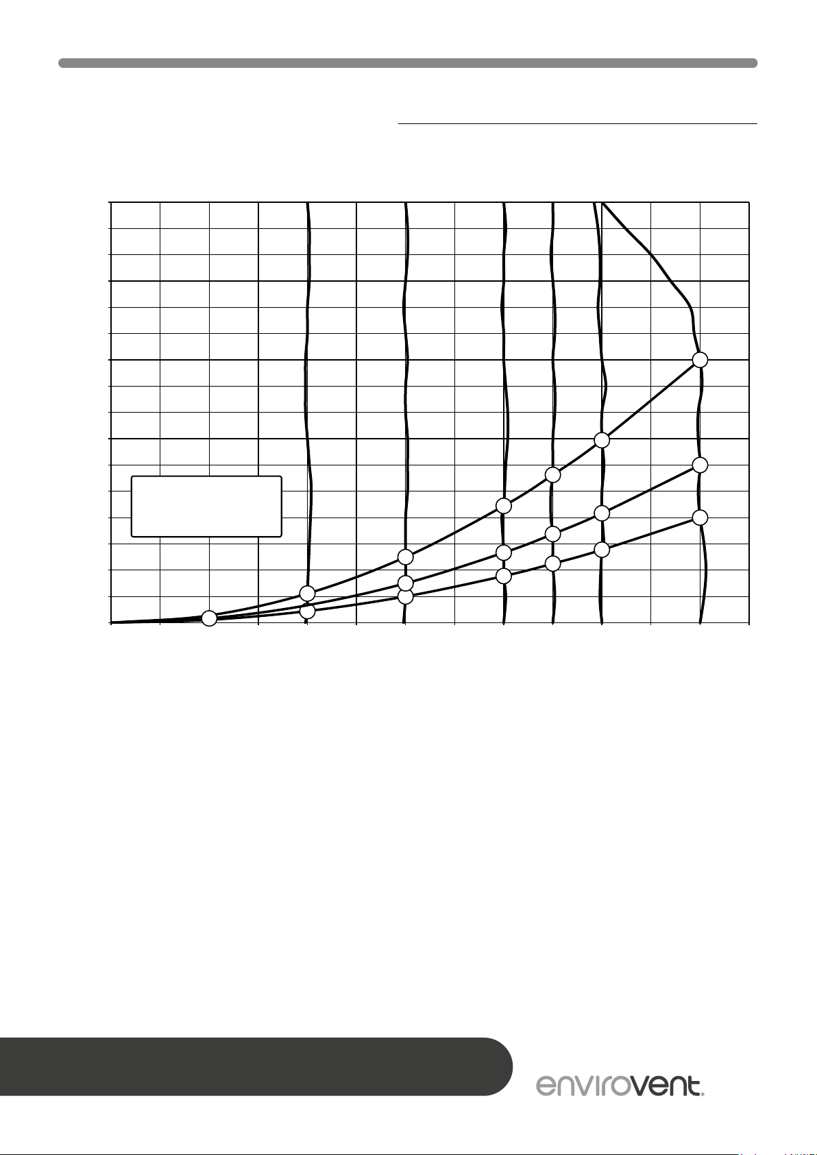
0 25 50 75 100 125 150 175 200 225 250 275 300 325
energiSava 300 fan graph
400
375
350
325
300
275
250
225
200
175
150
125
100
Resistance ducts system (Pa)
75
50
25
Note: The value stated in
the circle is the capacity
per fan (in Watt)
0
5
69
44
33
26
27
15
8
7
12
11
23
19
23
33
28
52
46
Flow rate [m3/h]
AFTER INSTALLING THIS UNIT PLEASE PASS ONTO END USER
DO NOT THROW AWAY
06
02 Technical Specications
energiSava 400
Supply voltage (V/Hz) 230/50
Protection degree IP30
Dimensions (w x h x d) (mm) 677 x 765 x 564
Duct diameter (mm) Ø180
External diameter condensate
discharge (mm)
Weight (kg) 38
Filter class G3 (F7 optional for supply)
Fan setting (factory setting) 1 2 3
Ventilation capacity (m
Permissible resistance ducts
system (Pa)
Rated power (excl. preheater) (W) 8.6 9.5 - 15.0 29.0 - 40.0 72.0 - 98.0
Rated current (excl. preheater) (AA) 0.10 0.12 - 0.14 0.24 - 0.31 0.51 - 0.70
Max. rated current (with preheater
switched on) (A)
Cos φ 0.38 0.45 - 0.40 0.56 - 0.58 0.60 - 0.61
3
/h) 50 100 200 300
3 - 6 6 - 20 25 - 79 56 - 178
Ø32
6
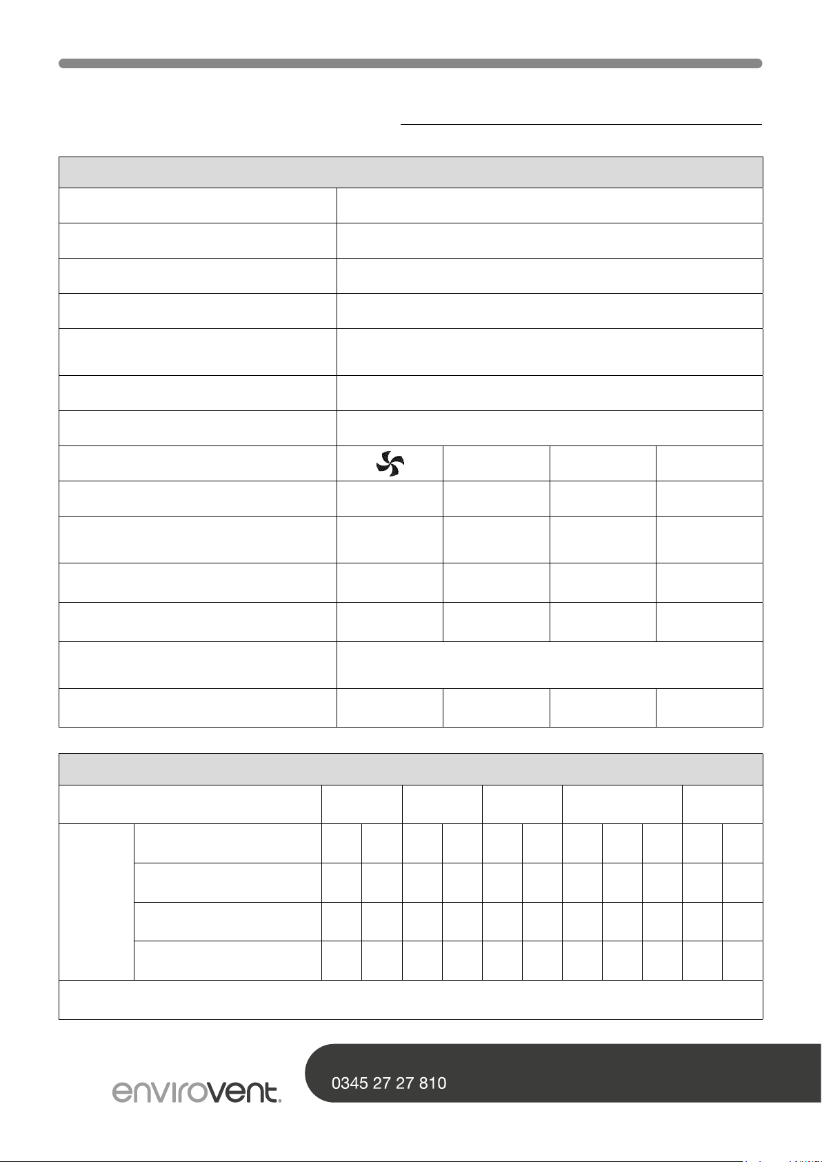
Sound Power energiSava 400
3
Ventilation capacity (m
Static pressure (Pa) 9 40 38 80 47 100 84 175 240 150 225
Sound
power
level
Lw (A)
In practice, the value may deviate 1 dB(A) as a result of measuring tolerances
Housing emission dB(A) 29.5 32.5 40.5 40.5 43.5 47.5 51.0 53.0 54.0 54.5 57.0
Duct from dwelling dB(A) 31.5 34.5 46.5 48.0 48.5 50.0 56.5 57.0 58.0 59.0 60.0
Duct to dwelling dB(A) 42.5 47.5 57.0 59.0 60.5 62.5 66.0 68.5 69.5 70.5 71.5
/h) 100 200 225 300 400
SHOULD YOU ENCOUNTER ANY PROBLEMS INSTALLING THIS UNIT CALL
07

02 Technical Specications
energiSava 400 fan graph
400
375
350
325
300
275
250
225
200
175
150
125
100
Resistance ducts system (Pa)
75
50
25
Note: The value stated in
the circle is the capacity
per fan (in Watt)
12
0
0 25 50 75 100 125 150 175 200 225 250 275 300 325 350 375 400 425
5
7
10
20
17
15
32
26
28
22
23
19
49
40
36
86
79
58
51
Flow rate [m3/h]
83
71
AFTER INSTALLING THIS UNIT PLEASE PASS ONTO END USER
DO NOT THROW AWAY
08
02 Technical Specications
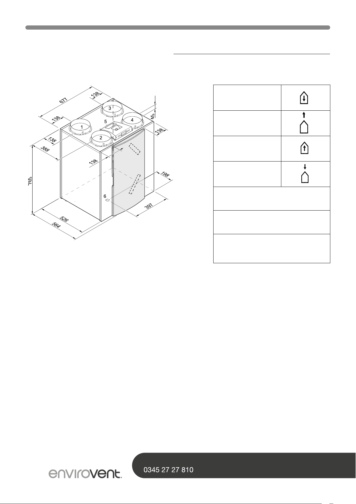
Connections & dimensions - Right handed version
1. To dwelling
2. To atmosphere
3. From dwelling
4. From atmosphere
5. Electric connections
6. Connection condensate discharge
Right-handed 4/0
7. Wall mounting bracket (note the
correct position of the rubber strip,
washers and caps)
09
SHOULD YOU ENCOUNTER ANY PROBLEMS INSTALLING THIS UNIT CALL
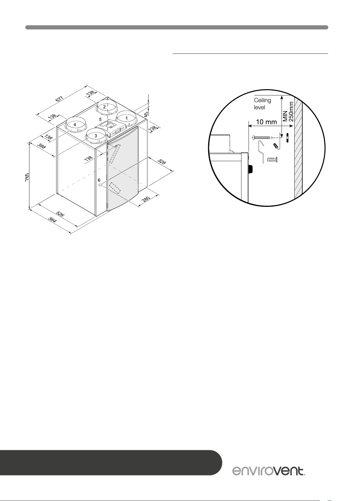
02 Technical Specications
Connections & dimensions - Left handed version
7
Mounting wall suspension kit
Left-handed 4/0
AFTER INSTALLING THIS UNIT PLEASE PASS ONTO END USER
DO NOT THROW AWAY
10

02 Technical Specications
Rear view display cover
(Plus version)
1 Service connector Computer connection for service purposes
2 Display and 4 control buttons Interface between user and control electronics
3 Control board Contains the control electronics for the basic functions
4 Extract air lter Filters air ow from dwelling
5 Preheater Heats up the outdoor air when there is a risk of freezing in the heat exchanger
6 Heat exchanger Ensures heat transfer between input and output air
7 Supply air lter Filters outdoor are supplied to the dwelling
8 Bypass valve
9 Outdoor temperature sensor Measures outside air temperature
10 Indoor temperature sensor Measures the dwelling air temperature
11 Condensate discharge Connection condensate discharge (Kit comes separately with the appliance)
12 Extract fan Discharges air from the dwelling to the atmosphere
13 Supply fan Feeds fresh air into the dwelling
14 Modular connector multiple switch X2 Connections for cable to multiple switch, if desired with lter indicator
15 Connector eBus X1 Connection for eBus control
16 Connector X15 Contains the various control inputs and outputs; only for Plus version
17 Connector X14
18 Mains cable 230V Gland power cable 230V
19 Connection to postheater Gland 230V cable to postheateror extra preheater; only for Plus version
Sends the air through or around the heat exchanger (For 4/0 this valve is
in the upper part of the appliance)
Connection postheater; only for Plus version (accessible after taking o
the display cover)
11
SHOULD YOU ENCOUNTER ANY PROBLEMS INSTALLING THIS UNIT CALL
02 Technical Specications
The appliance is supplied ready to wire into
the fuse spur and operates fully automatically.
The extracted indoor air heats up the fresh,
clean outdoor air. That saves energy and
fresh air is sent to the required rooms.
The control system has three ventilation
modes. The air ow rate can be adjusted
per ventilation mode. The constant volume
control system ensures that the air ow
rate of the supply and extract fans is
always delivered despite any resistance
encountered in the ductwork.
The standard bypass valve makes it possible
to supply fresh outside air that is not heated
by the heat exchanger. Particularly during
summer nights it is desirable to supply
cooler outside air. In this mode the hot air in
the dwelling is replaced by cooler outside air
as far as possible.
The bypass valve opens and closes
automatically when a number of conditions
are satised (refer to the table below for
bypass conditions).
The operation of the bypass valve can be
adjusted in step number 5, 6 and step
number 7 in the settings menu (see page
41).
To prevent freezing of the heat exchanger
at extremely low outdoor temperatures,
the energiSava 300 & 400 features an
intelligent frost control. Temperature sensors
measure the temperatures across the heat
exchanger and, if necessary, the preheater
is switched on. This guarantees a proper
ventilation balance, even at very low outdoor
temperatures.
-The outdoor temperature is higher than 10°C and
-The outdoor temperature is lower than the indoor temperature in the
Bypass valve open
Bypass valve closed
AFTER INSTALLING THIS UNIT PLEASE PASS ONTO END USER
DO NOT THROW AWAY
dwelling and
-The temperature in the dwelling is higher than the temperature set at step
no.5 in the settings menu
(set a standard at 22°C).
-The outdoor temperature is lower than 10°C or
-The outdoor temperature is higher than the indoor temperature in the
dwelling or
-The temperature from the dwelling is lower than the temperature set at
step no. 5 in the settings menu minus the set temperature by the hysteresis
(tolerance) (step no. 6), this temperature is factory set at 20°C (22.0°C
minus 2.0°C).
12
02 Technical Specications
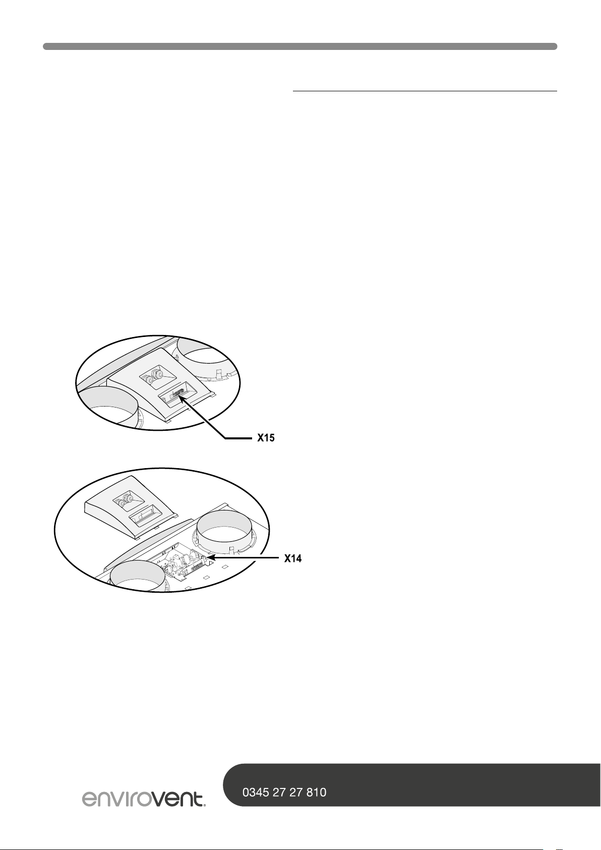
Plus version
The energiSava 300 & 400 are also available as a Plus version. This version is equipped with
a dierent control board with 2 additional connectors (X14 & X15) with more connection
options for various applications.
The 9-pole connector X15 is accessible at the rear of the unit display cover without having
to open the appliance.
The 2-pole connector X14 is accessible after taking o the display cover. The display cover of
the “Plus” version has a second gland. That makes it possible to feed a 230 volt cable, which
may be connected to connector X14, to outside the appliance.
See page 33 for more information on the connection possibilities of connectors X14 and X15.
13
SHOULD YOU ENCOUNTER ANY PROBLEMS INSTALLING THIS UNIT CALL
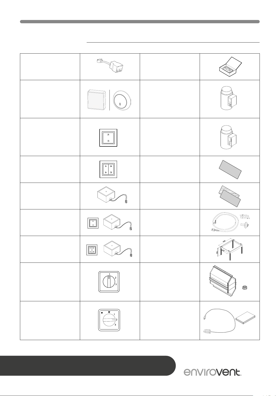
03 Accessories
F7
2x G4
F7
G3 +F7
G4 +F7
2X G3
2x G4
G4 + Frame
Splitter RJ12 Control unit
CO
sensor, ush
2
mounted eBus or
surface mounted
0-10V proportional
(PLUS version only)
Transmitter wireless
remote control 2
positions (with. battery)
Transmitter wireless
remote control 4
positions (with. battery)
Receiver wireless remote
control (for battery
version)
Kit wireless remote
control 2 positions (1
transmitter & 1 receiver)
Electric postheater
energiSava 300
Ø160mm
energiSava 400
Ø180mm
Electric (extra) preheater
energiSava 300
Ø160mm
energiSava 400
Ø180mm
Filter kit 1 x F7 lter
(1 pcs)
Filter kit 1x G3 & 1x F7
(1 pcs/ 1 pcs)
RH sensor
Kit wireless remote
control 4 positions (1
transmitter & 1 receiver)
3-way switch white
ush-mounted
(without lter indication)
Delivered with insert plate
and cover frame
4-way switch with lter
indication; ush mounted;
modular connection.
Delivered with insert plate
and cover frame
AFTER INSTALLING THIS UNIT PLEASE PASS ONTO END USER
DO NOT THROW AWAY
Mounting support
Enthalpie
heat exchanger
Service tool
14
 Loading...