

Page 1
energiSava 210
Instruction leaflet
Page 2

1. General information
2. Technical information
3. Installation
4. Characteristics and electrical connections
5. Commissioning the energiSava 210
6. Operating the energiSava 210
CONTENTS
The following items are included :
1. 1 x energiSava 210
2. 1 x remote control
3. 1 x wall bracket
4. 2 x drain ducts
5. 1 x drain connector
6. 1 x cable gland M12
7. 1 x cable gland M16
8. 1 x 4 connections tab
9. 1 x 3 connections tab
10. 1 x Instruction manual
Page 3

1. GENERAL INFORMATION
1.1 - Introduction
This manual is intended for the use of the central balanced-flow high efficiency energiSava 210
and its peripherals (ductwork, vents, controllers).
It is designed to provide clear and safe guidance for the design, installation and use of the
product.
The products are constantly evolving and so, Envirovent reserves the right to modify this manual
without prior notice.
1.2.- Warranty and Liability
Warranty
The energiSava 210 heat recovery system has three years warranty from the date of purchase.
This warranty includes free delivery of necessary spare parts.
The warranty does not cover:
Installation and removal costs
Defects that, in the opinion of Envirovent, are due to improper installation, handling, neglect or
accidental damage.
Those defects that arise as a result from operations or repair performed by a third party without
permission from Envirovent.
To return a defective part, the user should contact their installer.
Liability
EnergiSava 210 is designed for ventilation systems in individual dwellings.
Envirovent is not responsible for damage caused by:
• Improper use,
• Normal wear of components,
• Failure to follow the instructions in this manual concerning safety, use and installation.
• The use of parts not supplied by Envirovent.
1.3.- Safety
General health and safety standards
The heat exchanger energiSava 210 has been designed to be incorporated into a ventilation
system.
Following installation, there should be no risk to safety, health and the environment according to
EC directives. This also applies to other products used in the installation.
The following general guidelines are important:
Follow the safety instructions to prevent injuries and damage to the motorised fans.
The technical characteristics described in this manual may not be changed.
The motorised fans must not be modified.
The motorised fans must be supplied with a single phase AC supply of 230 V / 50 Hz.
So that the installation complies with EC directives, the energiSava 210 must be connected to
the electricity grid according to current national standards.
The device must be installed so that under normal operating conditions, there is no risk of
contact with moving parts and power.
The energiSava 210 meets legal requirements for electrical equipment.
Before working on the machine, always turn the power off.
Use appropriate tools.
Use the machine only for the purpose for which it is intended.
3
Page 4
2. TECHNICAL INFORMATION
2.1.- General information
The energiSava 210 ensures optimum ventilation of a house with a maximum energy recovery. It
draws air from the rooms (bathroom(s), toilet, kitchen and wash room(s)) and supplies fresh air
through the main rooms (living room, bedroom (s), office, etc ).
The fresh and extract airflows are separated and filtered. Only heat energy is transferred to the
fresh filtered air that is introduced. Due to the high-efficiency heat exchanger used in the
energiSava 210 performance can reach 95%.
Condensation forms during the heat exchange process and is recovered in the condensate tray,
which must be connected to a waste water drain.
The energiSava 210 is equipped with a double condensate drain system that allows use in
winter and summer for heated homes.
The energiSava 210 has a 100% heat exchanger bypass system and this allows the introduction
of fresh air at night without it being heated by contact with warm air accumulated in the house
during the day. The system operates automatically or can be used manually (see section 5-2).
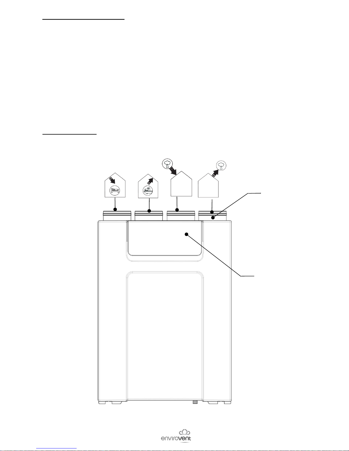
2.2.- Description
Access to Filters
D 125mm
Fresh air
inlet
Supply
fresh
air
Extraction
of stale
air
Discharge
to the
outside
4
Page 5
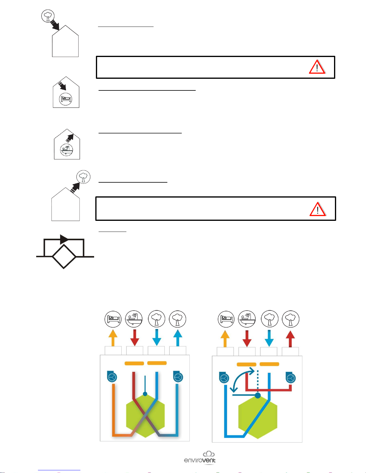
New fresh air inlet:
This spigot is to connect the supply duct of fresh air from outside.
Install the fresh air intake (wall or roof) a sufficient distance from any area of
high pollution (trees, exhaust fumes, road, etc).
This duct must be sealed and insulated to prevent condensation on
the outside and inside.
Supply fresh air into the building:
Connected to the air intake duct in the property.
To avoid thermal losses, it is recommended to use insulated ducts for the
warmed air.
Extract air from the building:
Connected to the extract duct from the property.
To avoid thermal losses and optimise the performance of the installation, it is
recommended to use insulated ducts for the warm air.
By-pass:
Having avoided the heat exchanger, the 100% by-pass system of the IDEO
allows the introduction of cooler fresh air in the night without it being warmed
by the warm air accumulated in the house during the day.
Discharge of extract air
Connected to the discharge duct to the outside.
This duct must be well sealed and thermally insulated to avoid
condensation both on the inside and outside.
Operation without
the bypass
Operation with
the bypass
5
Page 6
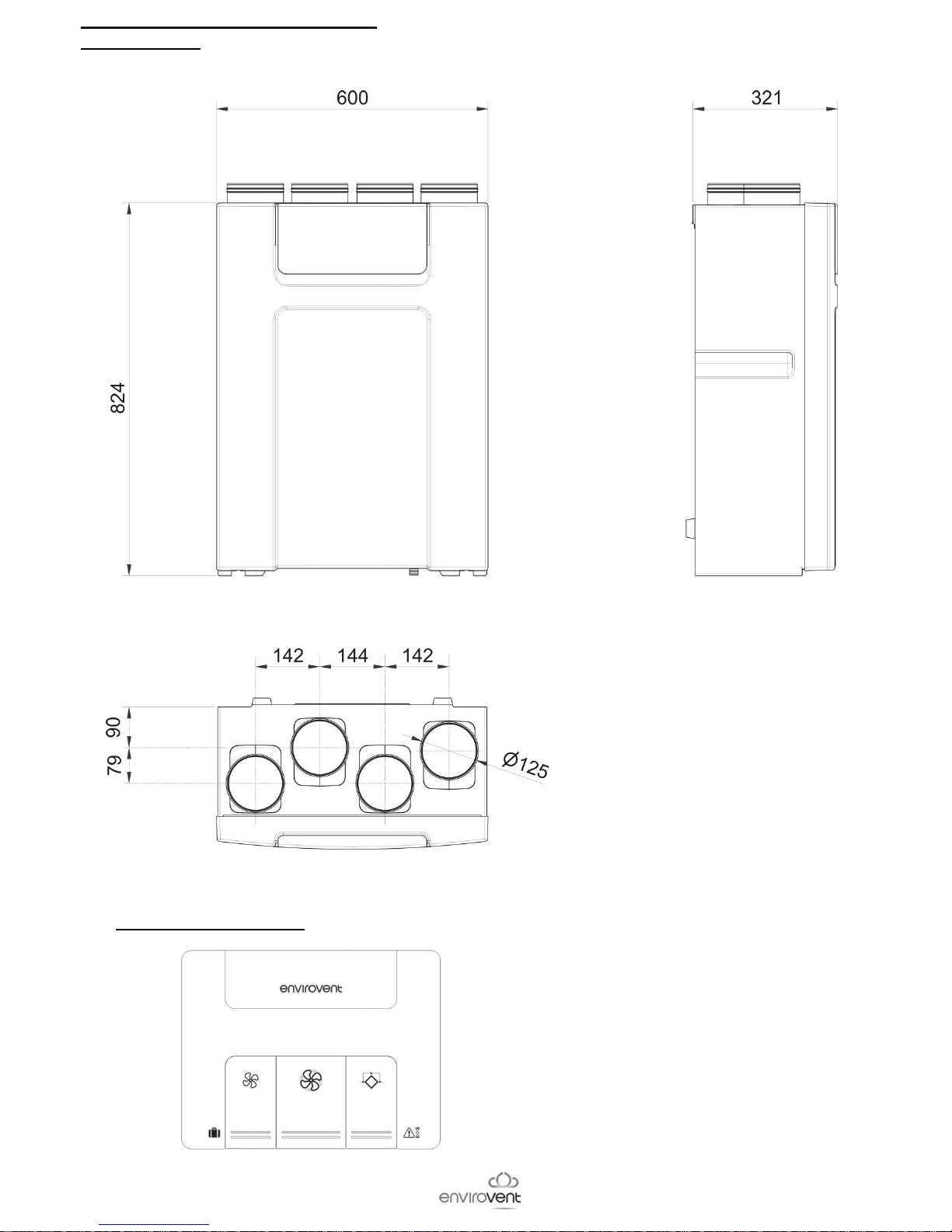
2.3.- Dimensional characteristics
2.3.a - Central:
Weight: 15Kg:
2.3.b - Remote control:
6
Page 7

3- INSTALLATION
Uninsulated
duct
Insulated duct
Insulated duct
Ducts must be insulated and
correctly installed.
In areas where temperatures are regularly negative or can drop below -10ºC, it is
advisable to install a preheating battery.
It is advisable to install the energiSava 210 in the heated area of the house. If
not, it is essential to isolate the condensation drain.
7
Wall bracket
Page 8

• Heating housing
In summer, in this configuration, the condensation is generated on the other side of the heat
exchanger. So, the energiSava 210 is equipped with a dual condensate drain system.
• Installing and connecting the drain kit for heated housing
1
2 3
4
5
6
7
8
Page 9

SAMPLE ” DISTRIBUTION” ASSEMBLY
Air intake
PAF 125
kitchen
Toilets
Living room
&
(*):Bedrooms
Or
CPR or CT
125
BDO or BOAP
125
BDO or TPM 80
If using insulated
flexible ducting it
is imperative to
fully stretch it.
Or
Air intake
PAQS125
BDO or TPM 80
RD 80*
RD 80
9
PLENUM UNI EX
5P/125
PLENUM UNI 6P/125
Page 10

Kitchen
Bathrooms
CPR or CT
125
BDO or BOAP
125
BDO or TPM
80 +
RD80
BDO 80
+
RD80*
+
*
+
Air intake
PAF 125
Or
Or
Air intake
PAQS125
SAMPLE “DISTRIBUTION” ASSEMBLY
Living Room
&
(*):Bedrooms
If using insulated
flexible duct, it is
imperative to fully
stretch it.
10
Page 11

11
4 - CHARACTERISTICS AND ELECTRICAL CONNECTIONS
Connect the supplied cable to the mains using a sealed connection box.
Power:
Single phase 230V-50Hz
Max. current:
0,8 A
Max.Power:
80 W
Maximum ambient temperature:
50ºC
Maximum flow temperature:
45ºC
Power wire
type H05VV-F-3G0,75
Connection
box
Electrical panel
Control wire
type H05VV-F-4G0,25
Electrical
panel
Connection box
In areas where temperatures are regularly negative or can drop below -10ºC, it is advisable
to install a preheating battery.
3
5
6
2
1
4
• Installation of cable glands
Page 12

12
- Characteristics electronic chart
MODBUS (*)
By-Pass
Not functional
on this version
Regulation
extract motor
Regulation
supply motor
Power supply
motor
Extract fan
Power supply
motor
Supply fan
energiSava 210
power supply
Remote
control
Pre-heating and
post-heating
batteries (*)
External
sensor
0-10V(*)
Programming and reprogramming console
parameters (*)
Connector
Humidity
sensor
On/Off
contact (*)
RJ45
Pin 4 = Terminal B
Pin 5 = Terminal A
Pin 8 = Terminal 0
*: Not supplied
Page 13

5- COMMISSIONING OF THE energiSava 210
5.1.- For installation:
The remote control allows:
• Adjust the airflows (Minimum, kitchen boost and by-pass airflow (night cooling)
• Adjust the timing of a dirty filters (6, 9, 12 or 15 months) (factory setting 9 months)
• Adjust the balance of supply / extraction airflows (chimney or imbalance of airflow between
supply and extraction)
Adjust airflow
by-pass / cooling
Maximum
Airflow adjustment
Minimum
Airflow adjustment
5.1.a- Airflow adjustment:
Airflows depend on the configuration of the house, depending on the number of main rooms (living
room, dining room, bedroom, office, etc..) and the number of toilets and bathrooms.
Open the unit and set each potentiometer as shown in the table below according to the configuration
of the house, :
Measure the duct diameter at a maximum airflow(Boost or By-pass)
Minimum
airflow
(m3/h)-(l/s)
Adjustment
Qminimum
Maximum
airflow
(m3/h)-(l/s)
Adjustment
Qmaximum
Cooling
airflow
(m3/h)-(l/s)
Adjustment
Qcooling
60 - 16,7 0 120 - 33,3 0 120 - 33,3 0
75 - 20,8 1 135 - 37,5 1 135 - 37,5 1
90 - 25 2 150 - 41,7 2 150 - 41,7 2
105 - 29,2 3 165 - 45,8 3 165 - 45,8 3
120 - 33,3 4 180 - 50 4 180 - 50 4
135 - 37,5 5 195 - 54,2 5 195 - 54,2 5
- - 210 - 58,3 6 210 - 58,3 6
potentiometers/airflows setting
13
Page 14

Filters alarm timing
5.1.b - Timing dirty filters alarm
It is possible to set the timing to 6, 9, 12 or 15 months (9 months factory setting). Fouling is linked to
the external environment (pollution, pollen,..) and the use of housing (dust, cooking fats..). It is
advisable to modify this parameter after the second alarm. Of course, after the installation, the extract
air is dusty and not representative of a normal conditions. During the second filter check, if you notice
that the filters are clean you can increase the time (12 or 15 ,months). However, if you notice that the
filters are very dirty should decrease the time (6 months).
Open the box and adjust the timing as shown. To do this, set the micro contacts 1 and 2 by the
number of months to suit your installation.
6 months
9 months
(factory setting)
12 months
15 months
14
Page 15

Imbalanced airflows
5.1.c - Supply/extraction airflow out of balance adjustment
This setting can be useful in some cases:
1. Case of a chimney:
It is necessary to add a supplementary air supply equal to the extract airflow due to the natural
draught of the chimney.
There are two possibilities:
a. Create an air inlet specific to the chimney.
b. add an additional supply airflow to the calculated energiSava 210 airflow to
facilitate the natural draught of the chimney.
Follow the recommendations below:
• Ensure that all doors and windows are closed.
• Light a fire in the chimney,
• Adjust the imbalanced airflow with the potentiometer until there is a good draught of
the chimney.
Extraction airflow
The adjustment is made on the supply airflow compared with extraction
airflow.
2. Imbalance between supply and extract airflow:
This situation can occur when one of the two circuits is very unbalanced compared to the other.
In this case, adjust the airflow imbalance with the potentiometer.
Example:
• Minimum calculated airflow= 90m3/h
• Supply airflow necessary= 99 m3/h
→ Potentiometer position 5 = +10%
Potentiometer setting
% QSupply/QExtraction
15
Page 16

Holiday mode (Flashing red LED):
Press the left key for 3 seconds to activate Holiday mode (50% minimum airflow).
It is possible to return to normal mode by pressing the same key once more.
Filters alarm (red LED):
When the filters are dirty a red LED appears on the right hand key. The factory setting
is 9 months after commissioning or changing the filters. When changing the filters.
If the 9 month interval is not ideal for the configuration or use of your installation
(filters too dirty or clean) it is possible to adjust this setting from 6 to 15 months (in
3 monthly steps – see paragraph 5-1-b)
Once changes have been made push the button 3 seconds to deactivate the
alarm and reset the timer.
Minimum airflow (green LED):
When the energiSava 210 is in Boost mode, it is possible, by pressing the left button,
to return to the minimum airflow before ½ hour has elapsed
Boost kitchen (green LED):
A button that enables the boost airflow for the kitchen to be selected in ½-hour steps.
By-pass (green LED):
On having avoided the heat exchanger, the 100% by-pass system of the
energiSava 210 allows the introduction of fresh air in the night without being warmed
by
the warm air accumulated in the house during the day.
This system works automatically with this conditions:
- Tº inner >1+ Tº outer and Tº inner > 24ºC and Tº outer> 12ºC,
The specific airflow can be adjusted to optimize the cooling nigh time or free cooling
(see paragraph 5-1-a)
If you want , you can manually switch to by-pass mode for a period of 8 hours, by
pressing the by-pass button. During this operation it is possible to cancel this function
by pressing the by-pass key once more.
Kitchen Boost
By-pass
+
Filters reset
Minimum airflow
+
Holiday mode
5.2 - During use
The remote control allows the user to:
• Activate the kitchen boost for ½ hour.
• Return manually to the minimum airflow
• Put energiSava 210 in holiday mode
• Manually switch to by-pass mode
• Display filters alarm
• Reset filters alarm
16
Page 17

6 - SWITCHING ON THE energiSava 210
To start your energiSava 210 unit use the following process:
1. Verify that all system components are correctly installed and connected:
• Fresh air intake duct insulated and connected correctly (Do not use a fresh air intake
equipped with insect screen)
• Fresh air and exhaust ducts insulated and connected correctly
• Fresh air and exhaust vents connected
• Flow regulators mounted in the right direction (if installed)
• Air outlet using insulated duct and connected to the outside (Using a roof cowl or outlet
without an insect screen)
• Insulated flexible ducts taut and large radius bends (if installed)
• Check that the unused spigots on plenums are sealed (if installed)
• Condensation drain well connected (siphon)
• Check that all connections are sealed (on the energiSava 210, on plenums and vents)
• Check the setting of the power circuit breaker
2. Turn on the energiSava 210
3. Adjust the minimum airflow, the kitchen Boost and refresh rate (Free cooling).
17
Page 18

REF. 99999999
EnviroVent Ltd
Envirovent House
Hornbeam Business Park
Harrogate
Hg2 8PA
01423 810 810
info@envirovent.com
www.envirovent.comm
 Loading...