

Enviro-tex EVI35000, EVI65000, EVI80000 Installation And User Manual
1 | Page
Enviro-tex Commercial EVI Series - Air Source Heat Pumps
Installation and Users Guide
IMPORTANT SAFETY INSTRUCTIONS
READ AND FOLLOW ALL INSTRUCTIONS
RETAIN THIS GUIDE FOR FUTURE REFERENCE

2 | Page
Enviro-Tex Commercial EVI Series
Installation and User Guide
Customer Service
If you have any questions about ordering Air Source Heat Pump replacement parts and products,
please get in touch.
Customer Service and Technical Support
(Open from 9am-4pm Monday- Friday)
Phone: 01472 828086
Email:
info@enviro-tex.co.uk
Address: 169-177 Cleethorpe Road, Grimsby, DN31 3AX
Website:
www.enviro-tex.co.uk

3 | Page
Table of Contents
IMPORTANT SAFETY PRECAUTIONS............................................................................................... 5
Health and Safety (Materials)................................................................................................... 5
Important End User Safety Information................................................................................... 7
Section 1........................................................................................................................... 8
Introduction................................................................................................................................... 8
Product Overview..................................................................................................................... 8
General Features....................................................................................................................... 8
Section 2........................................................................................................................... 9
Installation..................................................................................................................................... 9
Materials needed for installation.............................................................................................. 9
Installation of Outdoor Unit.................................................................................................... 10
Suggested Installation Methods............................................................................................. 11
Water Connections................................................................................................................. 14
Plumbing Installation Requirements....................................................................................... 14
Electrical Connections............................................................................................................. 15
General Information............................................................................................................... 15
Electrical Wiring Diagram........................................................................................................ 16
Power Supply.......................................................................................................................... 17
Grounding and Over Current Protection................................................................................ 17
Controller PC Board Setting.................................................................................................... 17

4 | Page
Section 3......................................................................................................................... 18
Operating Heat Pump................................................................................................................... 18
LCD User-Friendly Interface Controller................................................................................... 18
General Instruction................................................................................................................. 18
Controller Panel...................................................................................................................... 18
Controller Set-up.....................................................................................................................19
1. Temperature Setting........................................................................................................ 19
2. System Status Display Value............................................................................................. 20
3. Clock Setting..................................................................................................................... 21
4. Timer Setting.................................................................................................................... 22
5. Manual/Forced Defrosting............................................................................................... 23
General Operating Guide..................................................................................................................... 23
Users Guide.......................................................................................................................................... 24
Product Protection............................................................................................................................... 24
Section 4......................................................................................................................... 26
General Maintenance.................................................................................................................. 26
Controller Error Codes........................................................................................................... 26
Inspection and Service........................................................................................................... 27
Owner Inspection................................................................................................................... 27
Trouble Shooting.................................................................................................................... 27
Problems and Corrective Action............................................................................................. 28
Section 5......................................................................................................................... 35
Components Assembly................................................................................................................. 35

5 | Page
-------------------------------------------------------------------
HEALTH AND SAFETY INFORMATION
------------------------------------------------------------------
INFORMATION FOR INSTALLER AND SERVICE ENGINEERS
Under the Consumer Protection Act 1987 and the Health and Safety at Work Act 1974, it is required
to provide information on substances hazardous to health (COSHH Regulations 1998).
Enviro-Tex takes every reasonable care to ensure that these products are designed and constructed
to meet these general safety requirements, provided they are properly installed and used.
To fulfil this requirement, products are comprehensively tested and examined before dispatch.
When working on the appliance, it is the responsibility of the user/engineer to ensure that any
necessary personal protective clothing or equipment is worn when appropriate for parts, which
could be considered hazardous or harmful.
This appliance may contain some of the items below:
Refrigerants
The appliance contains R407c refrigerant. The constituents of R407c are HFC’s R125, R134a and R32,
all of which have low toxicity levels.
When handling, avoid inhalation and contact with the skin and eyes. Suitable personal protective
equipment (PPE) must be worn (gloves, overalls, eye protection) and a comprehensive first aid kit
(containing eyewash) should be easily available.
Site engineers should have a certificate of competence and should know and understand the
properties and hazards before handling liquid refrigerants.
When the appliance has come to the end of its life span, an approved engineer must dispose of the
equipment and refrigerants in accordance with the EU laws.
Seek urgent medical attention if in haled or digested. Exposure to eyes and skin should be followed
by immediate cleansing of the affected areas and medical attention if necessary.
Insulation
Fibre insulation may be irritating to the skin, eyes, nose and throat. When handling, avoid inhalation
and contact with the eyes. Use disposable gloves, facemasks and eye protection.
After handling, wash hands and other exposed parts. When disposing, reduce dust with water spray
and ensure all parts are securely wrapped.
Glue, Sealants and Paints
Glue, sealants and paints are used in this appliance and present no known hazards when used in the
manner of which they are intended.

6 | Page
IMPORTANT SAFETY INFORMATION FOR THE END-USER
• Installation of the appliance must only be carried out by persons with suitable
engineering qualifications.
• Do not attempt to modify, repair or service the appliance yourself.
• Do not insert body parts or any other items into the air inlet or outlet.
• Do not start or stop the unit by removing the power cable; always use the controls
and switches provided.
• If installed outside, ensure the appliance is protected from prolonged exposure to
large quantities of water.
• Do not operate the unit or the programmer with wet fingers.
• Upon replacement of the fuse, ensure an adequate replacement is used (e.g not
fuse wire)
• Keep the programmer unit of out of reach of children.
• The electrical supply must be isolated during a heightened risk of lightning strikes.
• Do not attempt to move the appliance once it is installed; this must be carried out
by a qualified engineer.
• Isolate the electrical supply to the appliance if an odour presents, or scorching is
detected.
• Only use this appliance for the purpose intended.
• Ensure the area around the appliance is clean, well-ventilated and kept free of all
obstructions.
• Do not keep items on top of the appliance or use it to support other appliances.
• Do not under any circumstances stand on the appliance.
• Isolate the electrical supply to the appliance if it is to be switched off for a period
of more than two weeks.
• Drain the water from the water circuit if power to the unit is to be switched off
during very cold weather.
• Periodically check the condition of any supports for deterioration.
• Do not wash the unit with water, alcohol, benzene, thinner, glass cleaner, polish or
powders.
• During cleaning, isolate the electrical supply to the appliance.

7 | Page
Section 1
Introduction
Product Overview
Air Source Heat Pumps transfer heat from the ambient air to water, providing high-temperature hot
water up to 60°C. The unique Enviro-tex heat pump is widely used for house heating.
With our innovative & advanced technology, the EVI range of heat pumps can operate very well at
-25°C ambient temperature with high output temperatures up to 60°C, which ensures the
compatibility with normal sized radiator based systems without supplementation. Compared with
traditional oil/LPG boilers, Enviro-Tex high-temperature heat pump produces up to 50% less CO²
whilst saves up to 80% on running costs. Enviro-Tex heat pumps are not only highly efficient, but
also easy and safe to operate.
General Features
1. Low running costs and high efficiency.
• A high coefficient of performance (COP) of up to 5, results in lower running costs
compared with traditional ASHP technology.
• No immersion heater supplement is required.
2. Reduced Capital Costs.
• Simple installation
• Compatible with traditional radiator systems, eliminating the expense of installing
under floor heating or changing to oversized radiators.
3. High Comfort Levels.
• High storage temperature results in increased hot water availability.
4. No potential danger of any inflammable, gas poisoning, explosion, fire, electrical shock
which are associated with other heating systems.
5. A digital controller is incorporated to maintain the desired water temperature.
6. Long-life and corrosion resistant composite cabinet stands up to severe climates.
7. The latest EVI compressor ensures outstanding performance, ultra energy efficiency,
durability and quiet operation.
8. Self-diagnostic control panel monitors and troubleshoots heat pump operations to ensure
safe and reliable operations.
9. Intelligent digital controller with friendly user interface and blue LED back light.
10. Separate isolated electrical compartment prevents internal corrosion and extends heat
pump life.
11. The heat pump can operate down to ambient air temperature of -25°C.
8 | Page
Section 2
Installation
The following general information describes how to install the air source heat pump.
Note: Before installing this product, read and follow all warning notices and instructions. Only a
qualified / competent person should install the heat pump.
Materials needed for Installation:
The following items are needed and are to be supplied by the installer for all heat pump
installations:
1. Plumping fittings.
2. Level surface for proper drainage.
3. Ensure that a suitable electrical supply cable is provided. See the rating plate on the heat
pump for electrical specifications. Please take a note of the specific current rating. No
junction box is needed at the heat pump; Connections are made inside of the heat pump
electrical compartment. Conduit may be attached directly to the heat pump jacket.
4. It is advised to use PVC conduit for the electrical supply cables.
5. Use a correctly sized water pump to obtain minimum water flow rate.
6. A filter on the water inlet is needed.
7. The plumbing should be insulated to reduce heat losses.
Note: We recommend installing shut-off valves on the inlet and outlet water connections for ease of
serviceability.
Enviro-tex EVI Series Air Source Heat Pump Specification
Model EVI35000 EVI65000 EVI80000
Water Outlet Temp at 35/45°C
Ambient
Temp.
(20°C)
Normal Capacity
kW
35/33
64.9/59.8
79.3/72
Power Input
kW
8.52/9.3
16.4/18
19.8/21.8
COP
4.1/2.65
4.1/3.7
4.2/3.66
Ambient
Temp.
(7°C)
Normal Capacity
kW
29.1/27
54.5/50
68.5/62
Power Input
kW
8.2/9
15.8/17.5
19.4/21
COP
3.6/3.2
3.5/3.3
3.6/3.2
Max Power Input kW 11.5 21.8 42/46
Power Supply V/Ph/Hz 380~415/3/50 380~415/3/50 380~415/3/50
Rated Current A 12.7 24.3 30.3
Rated Water Flow m³/H 6.5 11.5 18.3
Rated Water Temp. °C 55
Max Water Temp. °C 60
Refrigerant R407C/2x4/0kg R407C/2x7.2kg R407C
Compressor
Copeland Scroll EVI
Net Weight
Kg
258
459
820
Dimensions
mm
1420x810x1050
1980x970x2070
1980/980/2070
Water Connections:
2”
3”
4”
Ambient Temp.
°C
-25~40
Noise
dB(A)
≤67
≤69
≤69
Note: The above design and specifications are subject to change without prior notice for product
improvement. For detailed specifications of the units please refer to name plate on the units.
9 | Page
Correct installation is required to ensure safe operation. The requirements for Enviro-Tex heat
pumps include the following:
1. Appropriate site location and clearances.
2. Wiring to conform to 17
th
edition wiring regulations.
3. Adequate water flow.
This manual provides the information needed to meet these requirements. Review all application
and installation procedures completely before continuing the installation.
Installation of Outdoor Unit
The heat pump should be installed on a solid level base that can take the weight, preferably a
concrete foundation. If concrete slabs are used they must rest on asphalt or shingle.
The heat pump should not be positioned next to sensitive walls, for example, next to a bedroom.
Also ensure that the placement does not inconvenience the neighbours. The heat pumps must not
be placed so that recirculation of the outdoor air can occur; this causes lower output and impaired
efficiency.
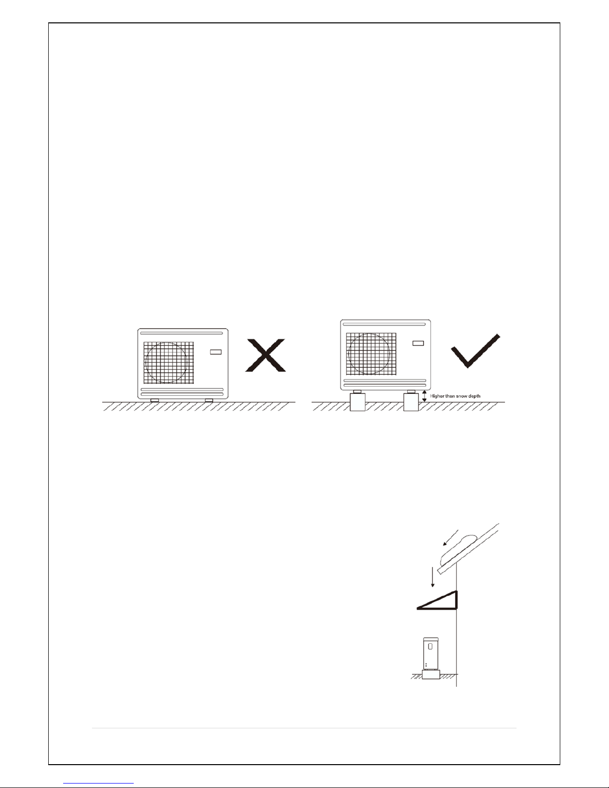
Large amounts of condensation water as well as melted waters from
defrosting can be produced. Condensation water must be led off to a
drain or similar.
The outdoor unit should be installed in a ventilated place, with enough
space for air inlet and outlet, while without thermal radiation or other
heat source. The air outlet should not be against the wind.
Generally, horizontal air flow type heat pump does not need sheltering.
The structure design has protected all internal components against rain
and sunshine. A shelter is necessary to avoid snow burying the heat
pump in heavy snow areas.
Please make sure the standardized voltage 380-415v is available to the
heat pump, otherwise the performance would be influenced and could affect your warranty.
10 | Page
The foundation of the heat pump can be a cement or steel structure. Anti-vibration rubber feet and
a flat foundation are generally required. The foundation structure can be flexibly designed according
to the working weight of the heat pump. (Please see the technical data in this manual.)
Water drainage should be available near the installation location for draining water in an effective
way. Do not install the heat pump in a place where there is polluting or corrosive materials like oil,
flammable and explosive gas and sulphide ect. Keep it far away from sands, falling leaves and area
with high-frequency equipment.
Installation on a balcony or on a roof-top must be in accordance with the allowable stress of the
building structure.
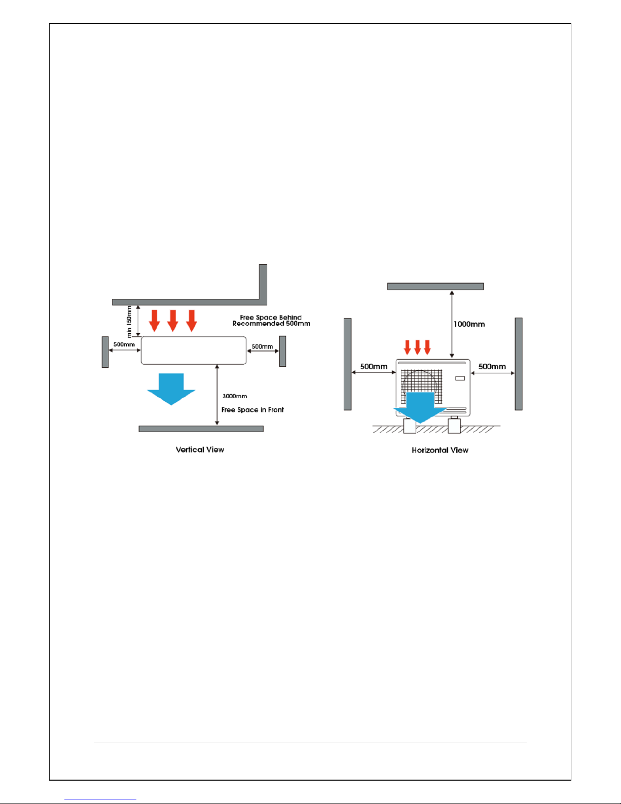
The installation space should be referred as follows:
Intake and outlet should not be obstructed. The wall the unit is to be mounted on should be strong
enough to bear the weight and vibrations of the unit.
Allow for proper clearances around the unit. Location should allow easy access for maintenance.
For any further guidance on heat pump installations for planning purposes, please consult the latest
version of the MCS guidelines or your local authority.
11 | Page
Suggested Installation Methods
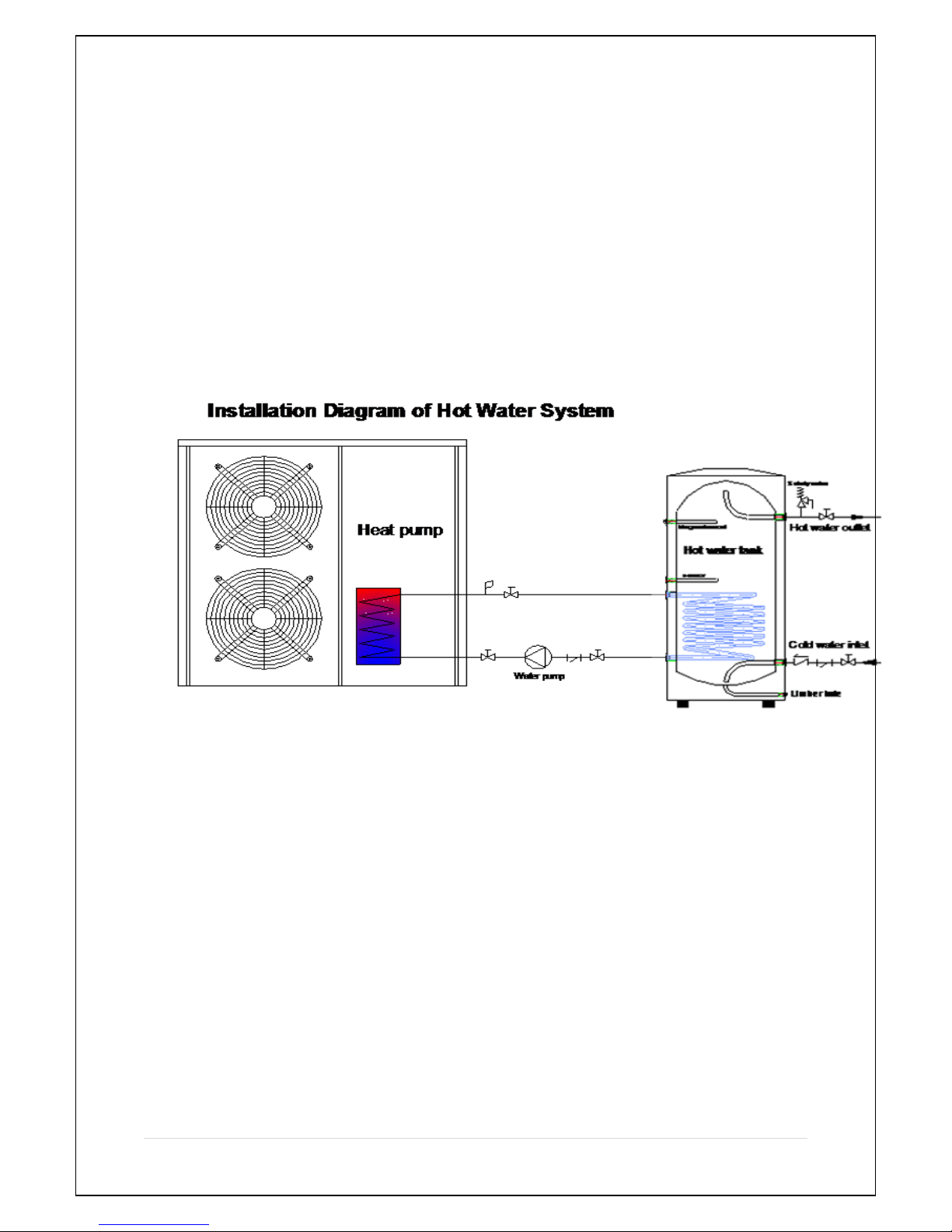
1. For hot water only / buffer tank, low loss header or thermal store installations, with or
without a coil. (See Figure 3)
The system is controlled by the programmer supplied and the thermostat probe only.
Please ensure this is properly located within the buffer or header.
(Figure 3)
12 | Page
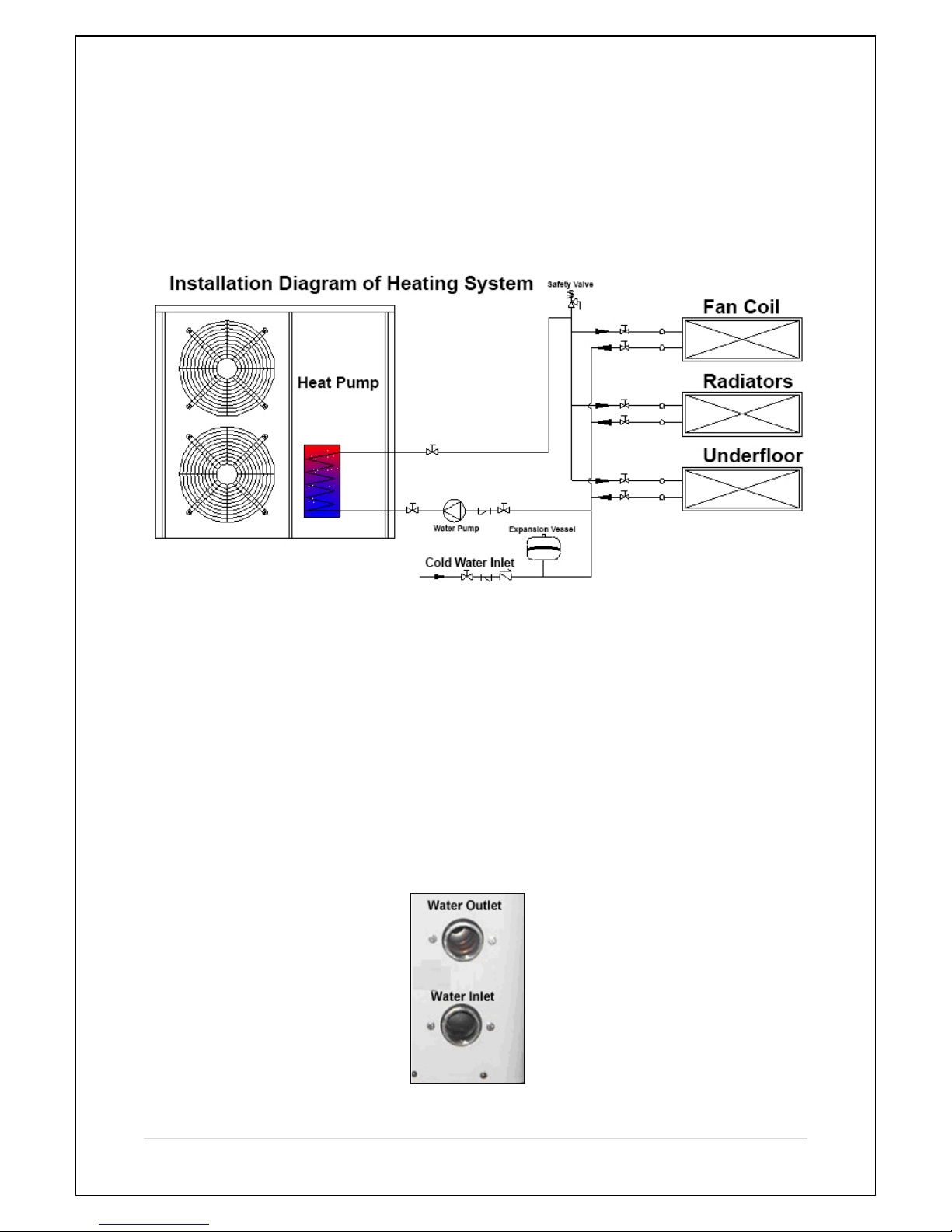
2. For direct heating only installation (See Figure 4)
The system is controlled by the programmer supplied and the thermostat probe only.
Please ensure this is properly located within the buffer or header.
The water flow rate through the unit must meet the minimum amount set.
(Figure 4)
Water Connections
Water connections at the heat pump
Flexible pipe fittings are recommended to be installed on the flow and return connections. (See
Figure 3).
(Figure 5)
 Loading...