


®
MANUAL
We manage heat
®
Freeze Protection Thermostat
TRACON® MODEL GPT–3
Installation and Operation Manual
Environmental Technology, Inc.
1850 N Sheridan Street
South Bend, Indiana 46628
(574) 233-1002 or (800) 234-4239
FAX (574) 233-2152 or (888) 234-4238
http://www.networketi.com/
20656 Rev. B 02/16 (800) 234-4239 http://www.networketi.com Environmental Technology, Inc.

Tracon® Model GPT-3 Freeze Protection Thermostat Installation and Operation Manual
2 of 12 Environmental Technology, Inc.
20656 Rev. B 02/16(800) 234-4239http://www.networketi.com

Table of Contents
Safety 4
Contacting Environmental Technology 4
General 5
Introduction 5
Operation 6
Normal 6
Abnormal 6
Installation 6
First 6
Next 6
Location 7
Supply and Heater Connections 7
Tracon® Model GPT-3 Freeze Protection Thermostat Installation and Operation Manual
Sensor and Alarm Relay Connections 8
General 8
Temperature Sensors 8
Alarm Relay Contacts 9
Setup 9
Factory Settings 9
Custom Settings 10
General 10
GFEP 10
Mode 11
Current 11
Constant Wattage Heater Mode 11
Maintenance 11
General 11
Troubleshooting 11
Returns 11
Specifications 12
20656 Rev. B 02/16 (800) 234-4239 http://www.networketi.com 3 of 12Environmental Technology, Inc.

Tracon® Model GPT-3 Freeze Protection Thermostat Installation and Operation Manual
Safety
Make all electrical connections in compliance with the National Electrical Code
(NFPA 70) and local electrical code. If you have questions concerning the installation
or application, contact Customer Service.
Abnormal Odor or Smoke
In the event of smoke or a burning or abnormal odor, immediately interrupt power
to the unit by unplugging the unit or by turning off the circuit breaker protecting the unit.
Electrical Shock / Fire Hazard
Even when the snow melting elements are disconnected, as long as the circuit
breaker is on and power is running to the unit, voltage is still being applied to the
system’s yellow leads. Therefore, never touch the ends of the yellow leads or let the
two leads touch each other. Do not let the two yellow leads contact any component
inside the unit.
Any installation involving electric heater wiring must be grounded to earth to
protect against shock and fire hazard. Suitable ground fault detection and interrupting systems must be in use at all times to reduce shock and fire hazard and to
protect equipment.
Electric wiring to heating elements must be installed in accordance with National
Electrical Code (NEC) requirements and all other local and applicable electrical codes
and any third party standards. Follow the installation instructions contained herein and
those provided by the heater manufacturer.
Use a GFEP (Ground Fault Equipment Protection) circuit breaker on each branch
circuit connected to the ice melting system. Clearly label each circuit breaker with its
function. This is vitally important when there is more than a single point of disconnect.
Size the circuit breaker in accordance with the size of the expected load. The
maximum current load for the GPT-3 is 30 Amps maximum. This product is intended
for use between electromechanical thermostats and high-end general purpose single
and multiple channel temperature controls.
Make certain that the heater shield is properly grounded. Failure to do so may
result in damage to the equipment or fire.
Additional Information
More information is made available regularly through our website,
www.networketi.com. Please visit us online for Data Sheets, Manuals, White Papers,
technical articles, and more. The most current and up to date version of this and every
other manual for our products can be found in Acrobat (PDF) format to view online or
to print. This is to assist you in installing and using our products to the best effect possible. If you have any comments about this or any other product from Environmental
Technology, Inc., please contact us.
Contacting Environmental Technology, Inc.
For assistance, please contact Customer Service. Office hours are from 8:00
AM until 5:00 PM ET.
Voice: (800) 234-4239 (USA and Canada) or (574) 233-1002 (elsewhere)
Fax: (888) 234-4238 (USA and Canada) or (574) 233-2152 (elsewhere)
E-mail: info@networketi.com
Mail: Environmental Technology, Inc.
1850 North Sheridan Street
South Bend, IN 46628
4 of 12 Environmental Technology, Inc.
20656 Rev. B 02/16(800) 234-4239http://www.networketi.com

Tracon® Model GPT-3 Freeze Protection Thermostat Installation and Operation Manual
General
Introduction
The GPT–3 Freeze Protection Thermostat has a calibrated adjustment range of
41° to 77°F (5° to 25°C) with a control band of 2°F (1°C). Heaters operate at ambient
temperatures below the set temperature.
The GPT–3 combines temperature control using either constant wattage or
self-limiting heaters with GFEP (ground fault equipment protection) and advanced
monitoring features. For example, although the GFEP is factory set to trip at 30 mA, this
threshhold can be set to 60, 90 or 120 mA to cure nuisance tripping problems. Keeping
wet fire sprinklers from freezing is considered to be a higher priority than interrupting
heater power in the event of a ground fault condition. The GPT–3 accommodates this
requirement by allowing the GFEP to be set only to alarm while the ground fault persists.
Other features include continuous heater monitoring with separate modes for
constant wattage and self-limiting heaters. A trickle current verifies heater continuity
of both heater types when there is no call for heat. The current flow through constant
wattage heaters verifies continuity during operation. Self-limiting heaters employ an independent temperature monitor sensor (included) to measure the hot-end temperature.
Depending upon how long it takes the cable to reach its operating temperature such
that the monitor sensor is less than 5°F (3°C) below the control sensor temperature,
the GPT–3 may momentarily declare a cold heater.
The GPT–3 automatically executes a self-test every 24 hours. First, heaters are
de-energized. Then, the GFEP verifies its own operation. Finally, it checks the heaters for
ground fault under operating conditions. This entire process takes about two seconds.
Other features include verifying the integrity of both the control and monitor
temperature sensors and checking the contactor for open or shorted contacts. A control
temperature sensor failure also inhibits contactor operation in addition to asserting
an alarm condition.
The GPT–3 automatically accommodates 120, 208, 240 and 277 supply voltages. Since the heaters and the GPT–3 operate from the same supply voltage, the
safety hazard created by multiple points of disconnect is eliminated. The heater control
contactor is rated for up to 30 amps.
The GPT–3 provides a reverse acting isolated Class 2 alarm relay contact SPDT
rated at one amp. Reverse action makes absence of supply voltage an alarmed condition.
Although the GPT–3 housing is NEMA 3R rated for indoor or outdoor service, a
protected location is recommended. The operating temperature range is −40° to 136°
F (−40° to 58°C). Padlocking the transparent front cover can prevent tampering without
interfering with the view of the status indicators.
Figure 1. GPT–3
dimensional drawing
20656 Rev. B 02/16 (800) 234-4239 http://www.networketi.com 5 of 12Environmental Technology, Inc.

Tracon® Model GPT-3 Freeze Protection Thermostat Installation and Operation Manual
Operation
Normal
The GPT–3 requires little or no attention after installation. Although changing the
temperature setting can improve heating system performance, this is seldom necessary. Minimum energy use occurs when the the temperature is set to the minimum
value providing the desired heating performance.
Normal operation occurs when neither the Fault nor the GFEP indicators operate
and the Alarm relay is off. Otherwise, operation is abnormal.
Abnormal
With one exception, operation of either the Alarm relay or Fault indicator or both
means that a failure has occurred that requires a qualified electrician to correct. The
exception is momentary indication of a self-limiting heater failure as is shown by blinking
the Heater indicator when the GPT–3 is used with self-limiting cable. The GPT–3 detects
a self-limiting heater failure by measuring its temperature at the far end of the cable.
Depending upon how long it takes the cable to reach its operating temperature such
that the monitor sensor is less than 5°F (3°C) below the control sensor temperature,
the GPT–3 may momentarily declare a cold heater.
How the GPT-3 LEDs Work
First two seconds (self test): all LEDs on.
After that:
Power LED: always on
Heater LED:
• Off:noalarm,noheat
• Onsteady:heating
• Flashonce:heateropen(notricklecur-
rent) [no control]
• Flashtwice:relaystuckon[nocontrol]
• Flashthreetimes:relaystuckof f(constantwattageonly)[nocontrol]
GFEPfaultLED:
• Off:normaloperation
• Blinkveryrapidly:ingroundfaulttest
• Blinkeven:groundfaultcondition[
nocontroliflatchingmode]
• Flashtwice:gfepcircuitfailure[no
controliflatching]
HeaterFaultLED:
• Off:normaloperation
• Blinkeven:lowtemp(self-limitingonly)
• Flashtwice:badcontrolthermistor[no
control]
• Flashthreetimes:badmonitorthermistor
Many indicators display additional information concerning equipment failures
through flashing (see “How the GPT-3 LEDs Work” at left). Check the Troubleshooting
section for additional information since service by qualified personnel is required.
Installation
First
Inspect the package and its contents for damage. In the event of damage, immediately contact Environmental Technology, Inc. Customer Service.
Next
Check the contents of the package against the pro forma Packing List shown
below. If discrepancies are found, contact ETI Customer Service before starting the
installation.
Pro Forma Packing List
Order Number Quantity Description
19425 1 GPT–3 Freeze Protection Thermostat
6 of 12 Environmental Technology, Inc.
25076 (or 19272) 2 Temperature Sensor
20656 1 GPT–3 Installation and Operation Manual
18703 4 Wire Nuts, Red
20656 Rev. B 02/16(800) 234-4239http://www.networketi.com

Tracon® Model GPT-3 Freeze Protection Thermostat Installation and Operation Manual
Location
The GPT–3 is suitable for indoor or outdoor mounting on a vertical surface.
Although the NEMA 3R rated housing is strong and durable, choose a protected location for an extra safety margin. Always consider the possibilities of tampering and
vandalism when choosing a location.
Keep the GPT–3 and the heat cable as close together as is practical to minimize
installation costs. There is a 2,000’ (610m) limit on temperature sensor extension wiring.
Figure 1 shows mechanical dimensions of the GPT–3. Note the location of the
compartment provided for low voltage Class 2 connections.
Supply and Heater Connections
The GPT–3 operates from 120, 208, 240 or 277 volts which it automatically
selects. The heaters and GPT–3 operate from the same supply voltage.
The definite purpose DPST heater control contactor is rated for up to 30 AMP
loads at 277 volts or less.
Make the supply voltage and heater connections in the compartment provided
for this purpose. Use only copper wire for supply, heater and safety ground connections. Select a minimum wire size of 10 AWG with, minimum, 300 volt insulation rated
for at least 75ºC.
Figure 2 shows a pictorial wiring diagram of the heater and supply voltage connections. Use appropriately rated wire nuts or bomb splices for all heater and supply
connections. Connect the equipment safety ground and heater shield ground to the
lug provided for this purpose.
Figure 2. GPT–3
wiring diagram
20656 Rev. B 02/16 (800) 234-4239 http://www.networketi.com 7 of 12Environmental Technology, Inc.

Tracon® Model GPT-3 Freeze Protection Thermostat Installation and Operation Manual
Sensor and Alarm Relay Connections
General
The two temperature sensors are connected to the terminal block in the low
voltage compartment along with the connections to the reverse acting isolated SPDT
alarm relay. Use #18 AWG copper wire with insulation rated for 300 volt service for all
Class 2 connections unless otherwise noted. Using jacketed extension wiring, although
convenient, is not necessary.
Using metallic conduit for extension wires is recommended. Never route Class
2 circuits in the conduit used for supply and heater voltage circuits.
Temperature Sensors
Two identical temperature sensors are supplied with the GPT–3. Each is supplied
with 20' (6m) of extension wire. For distances of up to 500' (152m), use #18 AWG
copper wire and #12AWG for up to 2,000' (610m). Temperature sensor connections
are non-polar.
Systems using self-limiting heaters require two temperature sensors. Figure 3
showsconnection of the two sensors. The GPT–3 comes factory set for self-limiting
cable.
Systems using constant-wattage heaters require only one sensor as is shown
in Figure 4 on the following page. Upon completion of the installation, dispose of the
unused sensor.
Figure 3. Control and monitor sensor
connections for self-limiting heaters
8 of 12 Environmental Technology, Inc.
20656 Rev. B 02/16(800) 234-4239http://www.networketi.com

Figure 4. Control sensor
connection for constant
wattage heaters
Tracon® Model GPT-3 Freeze Protection Thermostat Installation and Operation Manual
Alarm Relay Contacts
Figure 5 shows the alarm relay connections. The relay contacts are rated for one
amp in NEC Class 2 service. Contact Customer Service if higher voltage operation is
required.
Figure 5. Alarm
relay connections
Setup
Factory Settings
The GPT–3 comes set for the most common systems. This includes:
• Self-limitingcable
• GFEPsetat30mA
• GFEPsetformanualreset
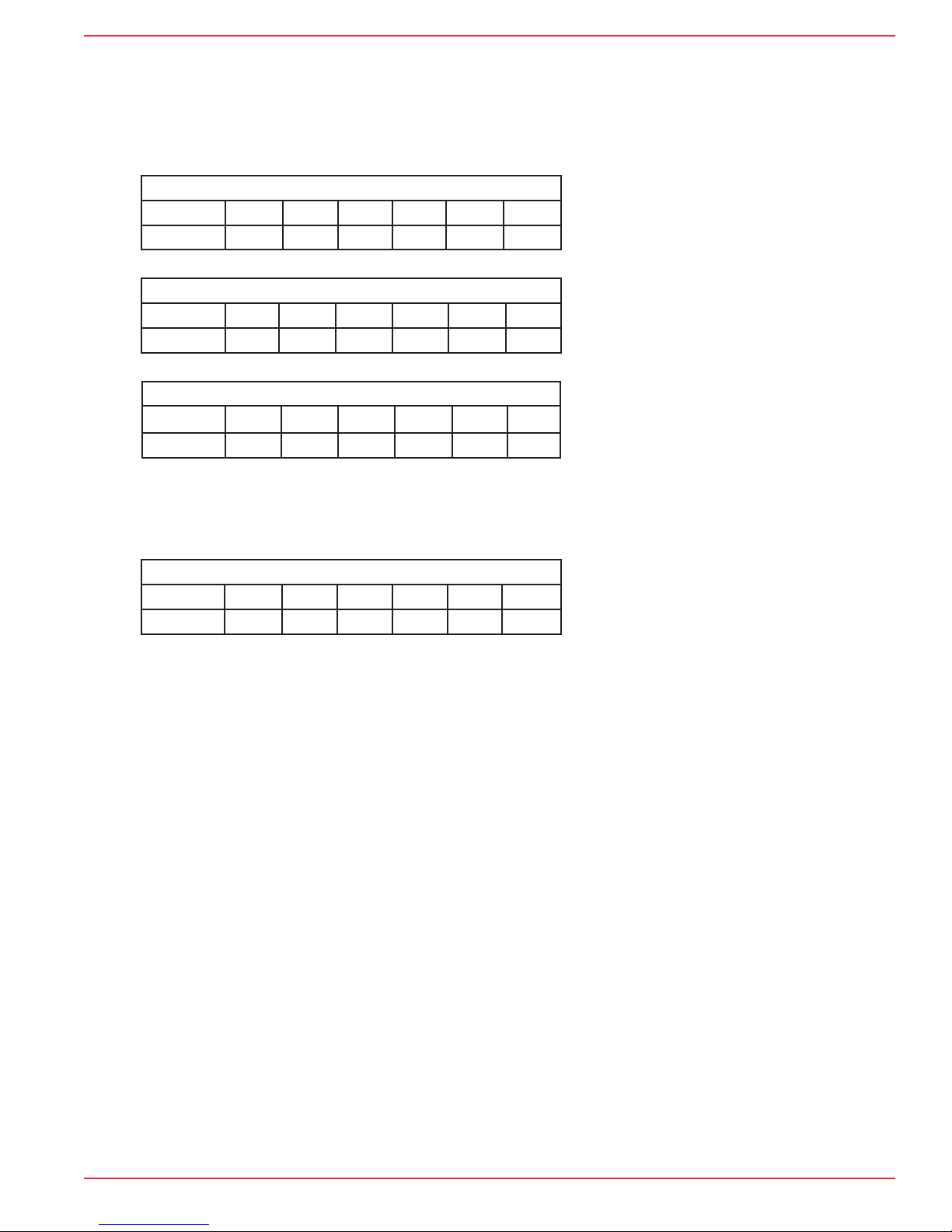
The factory DIP switch settings follow:
FACTORY SETTINGS
Pole 1 2 3 4 5 6
Setting Off Off Off Off --- ---
20656 Rev. B 02/16 (800) 234-4239 http://www.networketi.com 9 of 12Environmental Technology, Inc.

Tracon® Model GPT-3 Freeze Protection Thermostat Installation and Operation Manual
Custom Settings
General
The performance of the GPT–3 can be adjusted to match the needs of the application using the DIP switch as shown in Figure 6. Accessing this switch usually requires
removing the electronic assembly from its housing. Figure 7 shows the screws that
need to be removed to access the DIP switch.
Make any DIP switch changes before making the supply voltage and heater
connections. Otherwise, it will probably be necessary to break and re-make these
connections.
DIP switch poles that do not require change are labeled ‘NC’. Spare switch poles
are labeled ‘---’.
GFEP Mode
Fire protection sprinkler and certain other critical applications consider GFEP
secondary in importance to freeze protection. The GPT–3 accommodates these applications by warning of a ground fault condition while it exists. Heaters operate independent
of the ground fault condition.
Automatic GFEP Reset Setting
Pole 1 2 3 4 5 6
Setting On NC NC NC --- ----
Figure 6. DIP switch detail
Figure 7. Removing electronic assembly from housing
10 of 12 Environmental Technology, Inc.
20656 Rev. B 02/16(800) 234-4239http://www.networketi.com
Tracon® Model GPT-3 Freeze Protection Thermostat Installation and Operation Manual
Current
The GFEP current setting can be increased from its factory set 30 mA value
to 120 mA in 30 mA steps. The higher current settings serve the special purpose of
eliminating spurious GFEP tripping. Accessing this function was made intentionally
difficult to prevent its casual use. The DIP switch settings follow:
60 mA GFEP Setting
Pole 1 2 3 4 5 6
Setting NC NC On Off --- ---
90 mA GFEP Setting
Pole 1 2 3 4 5 6
Setting NC NC Off On --- ---
120 mA GFEP Setting
Pole 1 2 3 4 5 6
Setting NC NC On On --- ---
Constant Wattage Heater Mode
The GPT–3 provides a special operating mode for checking the continuity of
constant wattage heaters. The DIP switch setting is shown below:
Constant Wattage Heater Setting
Pole 1 2 3 4 5 6
Setting NC On NC NC --- ---
Maintenance
General
The GPT–3 does not require routine maintenance. It contains no field replaceable components.
Troubleshooting
The GPT–3 provides extensive fault diagnosis capability for the purpose of quickly
identifying and correcting system problems. Front panel indicators perform multiple
functions so as to provide the greatest amount of information. With one exception, one
or more indicators flashing in repetitive patterns mean that a fault requiring a qualified technician for correction has occurred. See “How the GPT-3 LEDs Work” at right.
The exception is operation of the HEATER FAULT indicator in a 50% on, 50% off
pattern when using self-limiting cable. This can occur when heaters first operate due
to the time delay between the application of power and attaining thermal equilibrium.
Detailed troubleshooting instruction can be obtained from either Customer Service
or the Environmental Technology, Inc. web site at http://www.networketi.com.
Returns
Contact Customer Service to obtain a Return Authorization before shipping
anything to Environmental Technology, Inc. Otherwise, the shipment may be refused.
20656 Rev. B 02/16 (800) 234-4239 http://www.networketi.com 11 of 12Environmental Technology, Inc.

Tracon® Model GPT-3 Freeze Protection Thermostat Installation and Operation Manual
SPECIFICATIONS
Control
Range –41°F to 77°F (–5°C to 25°C)
Dead Band 2°F (1°C)
Electrical
Supply voltage 120, 208, 240 or 277 volts auto-selected
Load 30 amps maximum
Alarm Relay Isolated SPDT 1 amp Class 2 contact
Indicators
Supply (Red) Power applied
Heater (yellow) Call for heat
GFEP (red) Ground fault occurring or has occurred
Fault (red) Contactor failure
Temperature sensor failure
Power-on sensor check failure
GFEP
Settings 30 mA default, 60, 90, 120 mA selectable
Reset Manaul Default
Auto-test Every 24 hours
Heater Monitoring
Choices Self-limiting default, constant wattage selectable
Alarm Relay No Power
Heater failure
Contactor failure
Ground fault of GFEP circuit failure
Temperature sensor failure
Temperature Limits
Operating –40°F to 136°F (–40°C to 58°C)
Storage –67°F to 167°F (–55°C to 75°C)
ORDERING INFORMATION
Order Number Description
19425 GPT-3 Freeze Protection Thermostat (QTY 1)
LIMITED WARRANTY
ETI’s two year limited warranty covering defects in workmanship and materials applies. Contact Customer Service for complete
warranty information.
DISCLAIMER
Environmental Technology, Inc., makes no representations or warranties, either expressed or implied, with respect to
the contents of this publication or the products that it describes, and specifically disclaims any implied warranties of
merchantability or fitness for any particular purpose. Environmental Technology, Inc., reserves the right to revise this
publication, and to make changes and improvements to the products described in this publication, without the obligation of
Environmental Technology, Inc. to notify any person or organization of such revisions, changes or improvements.
The ETI logo, We Manage Heat, Tracon and GPT are registered trademarks of Environmental Technology, Inc.
Copyright © 2013 Environmental Technology, Inc. All rights reserved. No part of this manual may be reproduced or translated in any form or by any means, electronic or mechanical including photocopying and recording, for any purpose without the express written consent of Environmental Technology, Inc. Printed in USA.
12 of 12 Environmental Technology, Inc.
20656 Rev. B 02/16(800) 234-4239http://www.networketi.com
 Loading...