

Page 1
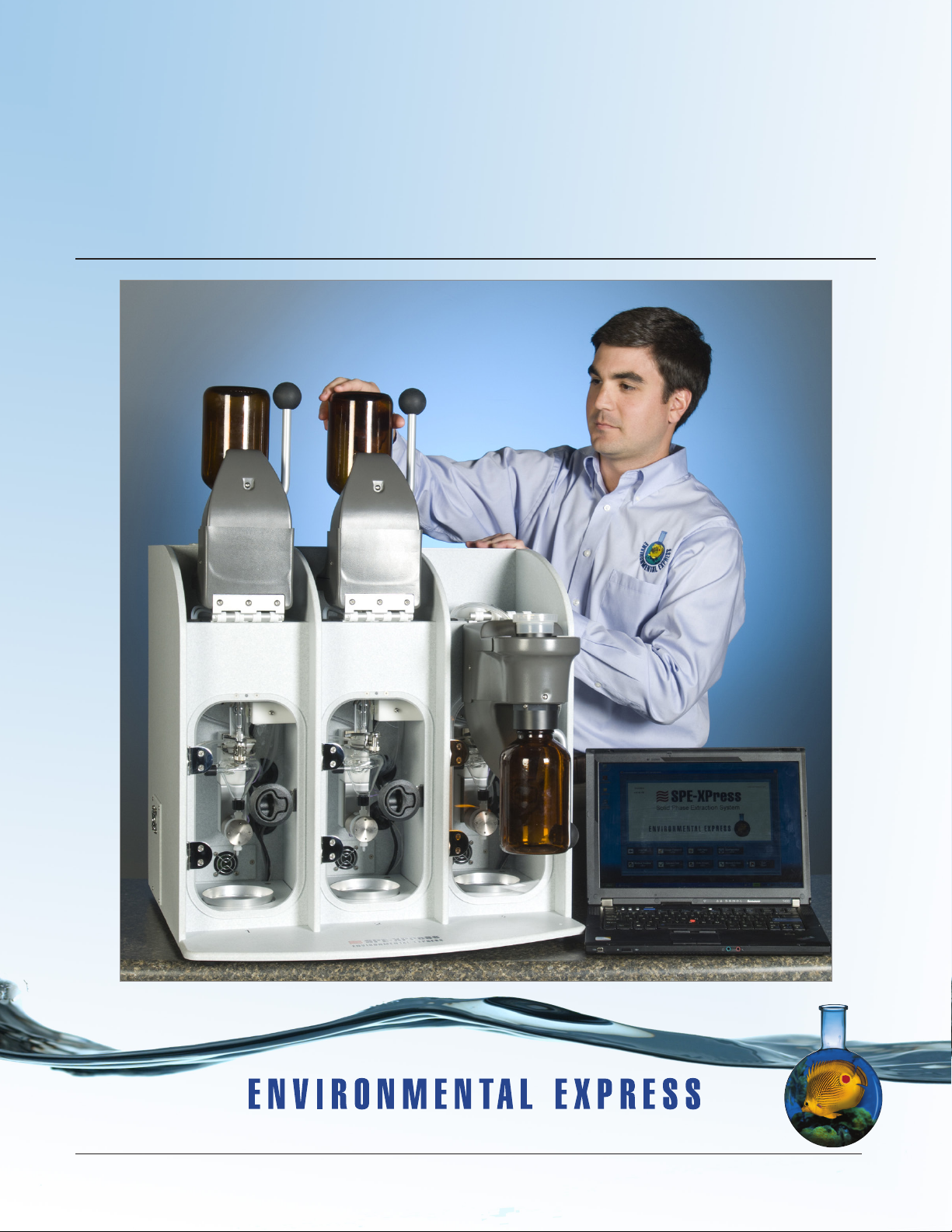
SPE-Express™ Automated System
for Oil and Grease
Operation & Instruction Manual
Call 800.343.5319 or 843.881.6560 • www.environmentalexpress.com
Copyright, Environmental Express, Inc, January 2013
Page 2

SPE$Express*Operation*and*Instruction*Manual*!
*
www.envexp.com*****!
!
"!
Contents
Product Features and Benefits 4
Specifications 5
1.0 General Information 6
1.1. Markings 6
1.2. Safety – Potential Hazards 6
1.3. Installation Requirements 6
1.3.1. Hardware 6
1.3.2. Software 6
1.4. Electrical Requirements 7
1.5. What’s Included 7
1.6. Other Items Needed 7
2.0 Getting Started 8
2.1 Unpacking Your Unit 8
2.2 Setting Up the Hardware 8
2.2.1 Electrical Connections 8
2.2.2 Reagent Tubing Kit 9
2.2.3 Nitrogen Ports 9
2.2.4 Filter O-Ring 10
2.2.5 Exhaust Duct 10
2.2.6 Flow Control Valve 10
2.2.7 Connecting Two Units 11
2.3 Setting Up the Software 12
2.3.1 Log-In Screen 14
2.3.2 Change Password Screen 14
2.3.3 Edit Users Screen 15
2.3.4 Add New User Screen 16
2.3.5 System Configuration Screen 17
2.3.6 Method Creation Screen 19
2.3.6.1 Pre-Rinse 19
2.3.6.2 Disk Activation 19
2.3.6.3 Sample Filtration 19
2.3.6.4 Elution 20
2.3.6.5 Solvent Evaporation 20
2.3.6.6 Method Parameters 21
2.4 Flushing the System 22
3.0 System Operation 24
3.1 Sample Set Up - Operator Test Screen 25
3.1.1 Pre-Test Interface 25
3.1.2 Station Status 25
3.1.3 Testing Status Summary 26
Page 3

Environmental*Express,*Inc.!
!
*****800.343.5319/843.881.6560!
!
#!
3.1.4 Test Control and Status 26
3.1.5 Bottle Rack Status 26
3.2 Operating A Test 27
3.2.1 Starting a Test 27
3.2.2 Flushing a Station 29
3.2.3 Draining a Station Manually 30
3.2.4 Cleaning a Station Manually 30
3.2.5 Aborting a Test 31
3.3 Operating Multiple Samples on One Station 31
3.4 Operating Multiple Stations 33
3.5 Operating Two Units 33
3.6 Manual Operation 34
3.6.1 Solenoid Control Interface 34
3.6.2 Ball Valve 35
3.6.3 Status Indicators 35
3.6.4 Main Fans 35
3.6.5 Sensor Chart 35
3.6.6 Temperature Control 36
3.6.7 Bottle Rack Status 36
3.6.8 Abort 36
3.6.9 Exit 36
4.0 Data Recovery 37
5.0 Care and Maintenance 38
5.1 Removing and Cleaning Lower Glass Chamber 38
5.2 Removing and Cleaning Barb Fittings 38
5.3 Cleaning the Sample Release Port 38
5.4 Replacing the Lower Glass Chamber 39
5.5 Recalibrating the Fluid Sensor 39
5.6 Changing the Bottle Adapters and Injection Heads 40
5.7 Detaching the Bottle Harness 41
6.0 Parts List 43
Page 4
SPE$Express*Operation*and*Instruction*Manual*!
*
www.envexp.com*****!
!
$!
The SPE-Express system is specifically designed for the extraction and evaporation required by EPA Method 1664 for Oil and
Grease Analysis.
SPE-Express is the ONLY system that:
• Both extracts your sample and evaporates the n-Hexane eliminating the transfer step
• Uses a fluid sensor to verify that the sample vessel is empty improving accuracy
• Runs multiple samples simultaneously on up to 6-stations improving analyst efficiency
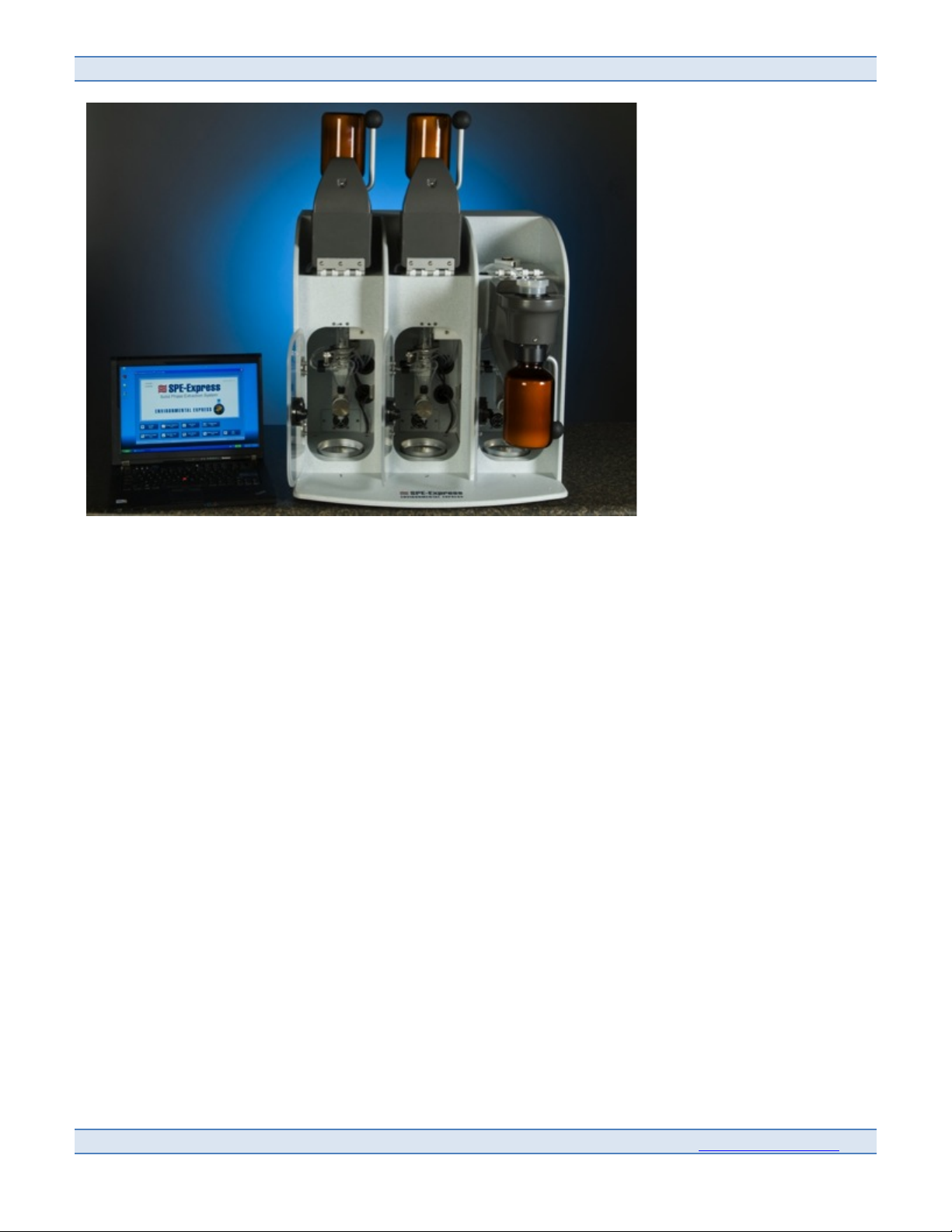
Simply load the 3-station SPE-Express with standard one-liter sampling jars and walk away. The system flushes itself clean,
preps the extraction disk, then filters and extracts the sample through sodium sulfate with n-Hexane. In the final stage the
SPE-Express automatically transfers the extract to a pre-weighed aluminum pan where it is evaporated to dryness. Remove
the pan for final weighing and the process is complete. User-friendly PC software controls the functionality while recording
data for downloading to LIMS.
SPE-Express is the only system that both extracts your sample and evaporates the n-Hexane. And the only one that utilizes a
fluid sensor to verify that the sample vessel is empty. It will reduce time and labor in your lab, improve accuracy plus
minimize analyst contact with hazardous chemicals.
Page 5

Environmental*Express,*Inc.!
!
*****800.343.5319/843.881.6560!
!
%!
Product Features and Benefits
•
Each system has three stations
•
Two systems can be joined and connected to one PC for a total of 6 stations
•
System is controlled with a PC using a single USB cable
•
System comes with software containing one default method and offers the ability for the customer to create
customized methods
•
System utilizes wide mouth amber jars designated by the EPA method
•
Each station can begin processing a new sample while a previous sample is being evaporated
•
SPE-Express software allows different users to have varying levels of access
•
System is available in 120 or 220 volts
SPE-Express performs the entire process through evaporation to dryness in approximately 40-45 minutes depending on
how dirty the sample is.
Prep – 5 Minutes
Filter Sample – 15 minutes
Elution – 15 minutes
Evaporation – 7 minutes
The SPE-Express automates Oil and Grease Extraction and Evaporation as outlined in EPA Method 1664:
Preps the System
• Rinses all system components with n-Hexane.
• Preps the extraction disk with Methanol then replaces the Methanol with DI water to avoid co-solvent elution.
Filters the Sample
• Vacuums the aqueous sample through the filter until the sample bottle is empty and all free liquid is removed from
the filter.
• Elutes the sample with n-Hexane and removes any sample residue from the sample bottle.
• Vacuum filters the eluted sample through the extraction disk then transfers the eluted n-Hexane through the drying
cartridge into a glass chamber.
Evaporates the Eluted Sample
• Transfers the sample to a heated, pre-weighed aluminum pan for evaporation to dryness.
• Allows the analyst to begin processing a new sample on the same station while the first is being evaporated.
Page 6
SPE$Express*Operation*and*Instruction*Manual*!
*
www.envexp.com*****!
!
&!
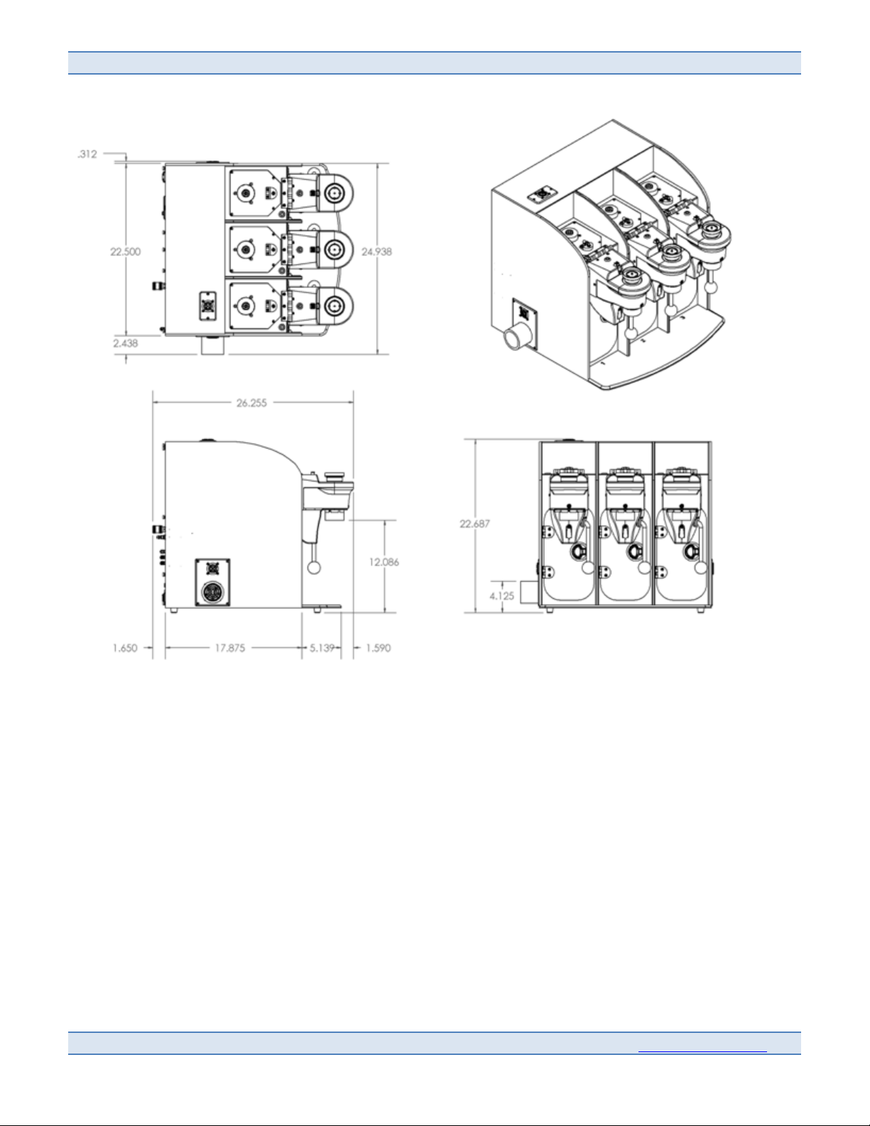
Unit Specifications
•
Unit Footprint: 22.5" w x 26.255" d x 22.343"h
•
Clearance: 2" all sides
•
Weight: 118 lbs.
•
Crated Weight: 200 lbs.
Page 7

Environmental*Express,*Inc.!
!
*****800.343.5319/843.881.6560!
!
'!
1.0 General Information
1.1 Markings
•
V = voltage
•
AC = alternating current
•
Hz = frequency
•
A = amperes
1.2 Safety – Potential Hazards:
•
The SPE-Express should only be operated by properly trained personnel using standard laboratory safety
practices.
•
Use extreme caution when operating the SPE-Express. During operation certain surfaces of the SPE-Express
may be too hot to safely touch with bare hands.
•
The SPE-Express contains electrical circuits, devices and components operating at dangerous voltages.
Contact with these circuits, devices and components can cause serious injury or painful electric shock.
•
Proper grounding is essential to avoid a potentially serious electric shock hazard. Ensure that there is an
internal ground connection between the system and the 3-pin, earth-grounded pin.
•
See individual SPE-Express specifications for power requirements.
•
Application of the wrong supply voltage can create a fire hazard and a potentially serious shock hazard,
and could seriously damage the SPE-Express system. See specifications for the SPE-Express system.
•
Users should be aware of the potential dangers from heating certain types of compounds and handling
certain types of chemicals. Such dangers may include explosion or the release of toxic or flammable gases.
•
Always lift the SPE-Express from the bottom, with one person on each side of the unit. Avoid lifting from
the front of the unit.
• Danger!!!()*+,-./!,-0!-12)3,-)!,4)!56)0!7-!8.-95-8*7.-!:7*+!*+76!);57<=)-*>!!?.*+!,4)!
)3*4)=)/@!A/,==,B/)!/7;5706!,-0!8,-!<4.058)!A/,==,B/)!C,<.46>!!D,<.46!=,@!8,56)!A/,6+!A74)>!!
D,<.46!,4)!+),C7)4!*+,-!,74!,-0!=,@!*4,C)/!*.!6.548)!.A!7E-7*7.-!,-0!A/,6+!B,8F>!!G.!.<)-!A/,=)6!
6+.5/0!B)!56)0!-),4!.4!,4.5-0!*+76!);57<=)-*>!!HC.70!,-@!7E-7*7.-!6.548)6!658+!,6!)38)66!+),*I!
)/)8*478,/!6<,4F6I!,-0!6*,*78!)/)8*478,/!8+,4E)6!:+)-!567-E!*+)6)!8+)=78,/6>!!J,=7/7,47K,*7.-!:7*+!
*+)!,<</78,B/)!(,*)47,/!L,A)*@!M,*,!L+)) *6!A.4!*+)!8+)=78,/6!56)0!:7*+!*+76!);57<=)-*!76!
6*4.-E/@!4)8.==)-0)0>!
1.3 Installation Requirements
1.3.1 Hardware
•
Locate the SPE-Express on a stable, level surface, and allow a minimum of 2" clearance on all sides.
•
The following environmental conditions should be observed:
- Ambient temperature range: 5°C - 30°C
- Ambient relative humidity: 0-90% RH
- Altitude: sea level to 2,500 meters
Page 8

SPE$Express*Operation*and*Instruction*Manual*!
*
www.envexp.com*****!
!
N!
1.3.2 Software
•
Computer must be Windows based, XP or newer with a minimum 2 GB RAM. Dual core processor
recommended.
1.4 Electrical Requirements
•
Required Voltage is 120VAC, ~60 Hz, 15A for the G8000 and 220-240VAC, ~50 Hz, 7.5A for the G8000-240.
•
Power should not vary greater than 10%. Use the supplied power cord or equivalent to connect to the
power supply. For safety reasons, a separate power receptacle should be provided for each SPE-Express.
Do not use extension cords or outlet adaptors. Make certain that power outlets are earth-grounded at the
grounding pin.
1.5 What’s Included
•
Box # 1:
SPE-Express System
Base 3-Station Unit
Software Flash Drive
Operation and Instruction Manual
•
Box # 2:
Reagent Rack Kit
Carboy
Tubing with Bottle Harnesses
•
Box # 3:
(2) 5.5 Gram Na2SO4 Drying Cartridges, 50 pack
Aluminum Weigh Dishes, 105mm, 100 pack
UltraFlow Filter Assemblies, Disposable 47mm, 100 pack
•
Other items included:
USB Cable, Power Cable, 15 Pack of Filter O-Rings, Fastener Tool, Adapter Wrench, Drying Cartridge
Extractor Tool, and Capacitive Sensor Calibration Tool, Reagents Pressure Hose
1.6 Other Items Needed
•
Vent Hose, 4" Diameter
•
Vacuum Source (vacuum connection should be an Industrial-Shape Quick Connection 0.25" Socket in
order to connect to the bottle harness)
•
Power Supply (specified page 7)
•
Sample Jars (Environmental Express Catalog # ESS09500050)
•
Nitrogen Source (70 psi minimum / 110 psi maximum). Other inert gases are acceptable. (Supply hoses
must be an Industrial-Shape Quick Connect 0.25" Socket in order to connect to unit).
•
Containers – All with GL38 threads
- N-Hexane Waste Container – 1 Liter
- n-Hexane Reagent Bottle - 4 Liter
- DI Water Bottle - 1 Liter
- Methanol - 1 Liter
Page 9
Environmental*Express,*Inc.!
!
*****800.343.5319/843.881.6560!
!
O!
2.0 Getting Started
2.1 Unpacking Your Unit
•
When unpacking your unit, remove the rubber plug from the filter adapter. Care should be taken not to allow
particulate matter to get into the filter adapter or it may cause damage to the station valves. Save the rubber
plug to be used in long periods of non-use. Always lift the SPE-Express from the bottom, with one person on
each side of the unit. Avoid lifting from the front of the unit.
2.2 Setting Up the Hardware
Please read the system requirements and electrical requirements on page 7 of the manual.
2.2.1 Electrical Connections
Secure the following connections:
• SPE-Express Power Cord to Power Source
• USB Port to PC
• Serial Cable to Bottle Rack (if equipped with Smart Bottle Rack)
He
x
a
n
e
Deionized Water
M
et
h
a
n
ol
Vacuum Source
Water Miscible Waste
Hexane Waste
Close Up, Reagent Tubing
Kit Connections
Figure 4
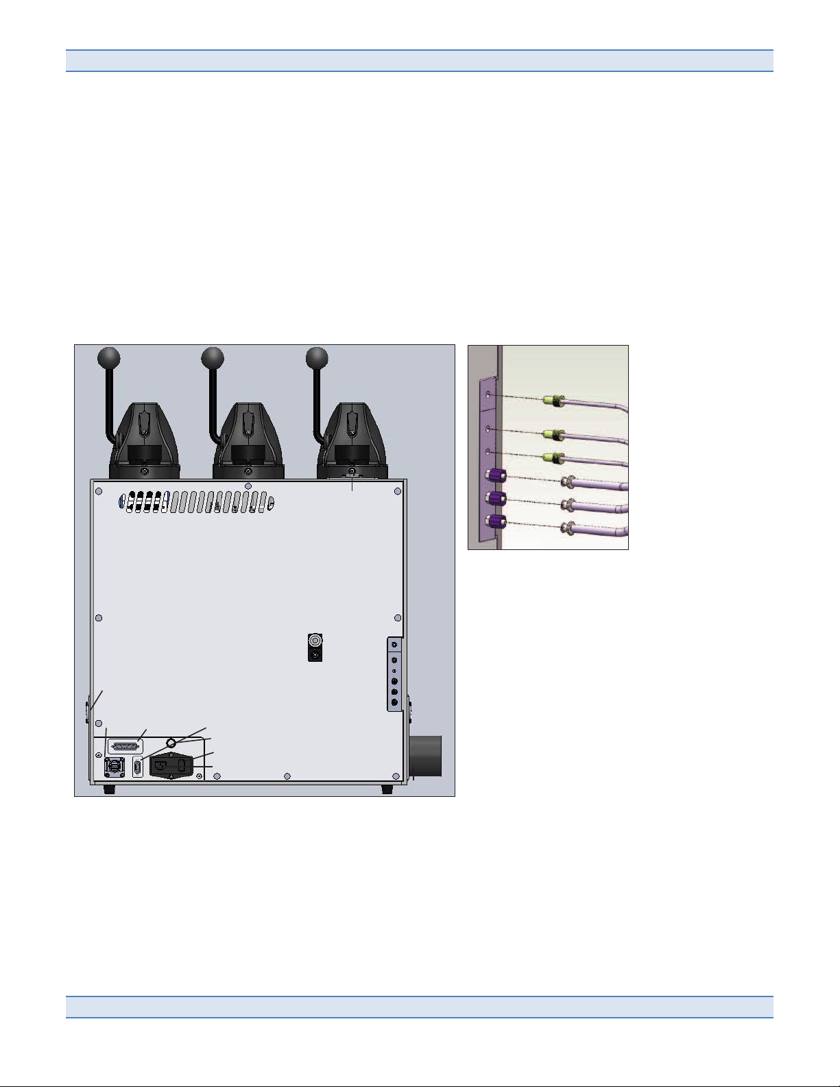
Figure 2
Nitrogen - from source
Nitrogen - to reagents
Hexane
Deionized Water
Methanol
Exhaust Fan
Power Cord
Serial Cable to Additional
SPE-XPress Unit
Power Indicator Light
Serial Cable to
Bottle Rack
USB Port
to PC
Vacuum Source
Water Miscible Waste
Hexane Waste
Vent Fan
Air Intake for
Exhausting
Unit
Power Switch
Figure 3
Page 10
SPE$Express*Operation*and*Instruction*Manual*!
*
www.envexp.com*****!
!
P!
2.2.2 Reagent Tubing Kit
Securely connect each tubing line to the appropriate port on the back of the unit (see detail diagram, page
8). Ensure the 3 luer fittings are tight by twisting the blue portion counterclockwise. Use the Fastener Tool
provided with the SPE-Express unit to tighten the Hexane, DI Water and Methanol lines.
•
Hexane
•
Deionized Water
•
Methanol
•
Vacuum
•
Water Miscible Waste
•
Hexane Waste
WARNING: Fluid connection, pressure must always be removed before disconnecting bottle harness from unit
to prevent leakage of chemicals. (Reference “Detaching the Bottle Harness” section for instructions for safe
removal of the bottle harness).
Replace reagents and waste container caps with the appropriate caps within the Bottle Harness. Ensure
Bottle Harness caps are tight on reagent bottles to prevent leaking.
Attach the Reagents Hose provided to the Bottle Harness manifold labeled “Pressure”.
Attach the Vacuum source to the Bottle Harness manifold labeled “Vacuum”.
Do not place reagents higher than the SPE-Express as it will affect spray volume performance.
Place reagents level with the SPE-Express or within 36" below.
CAUTION: Reagent bottles are under pressure while Nitrogen is supplied to the unit and reagents hose is
attached; never loosen reagent caps with Nitrogen supplied.
2.2.3 Nitrogen Ports
Ports are provided to control your Nitrogen flow.
Nitrogen from Source
The “Nitrogen - from Source” uses a hose with an Industrial-Shape Hose Quick Connect 0.25" Socket. The
other end should connect to the Nitrogen supply.
Nitrogen to Reagents
Connect the Reagents Pressure Hose Plug (opposite from the end connected to the “Pressure” manifold of
the Bottle Harness).
Page 11
Environmental*Express,*Inc.!
!
*****800.343.5319/843.881.6560!
!
"Q!
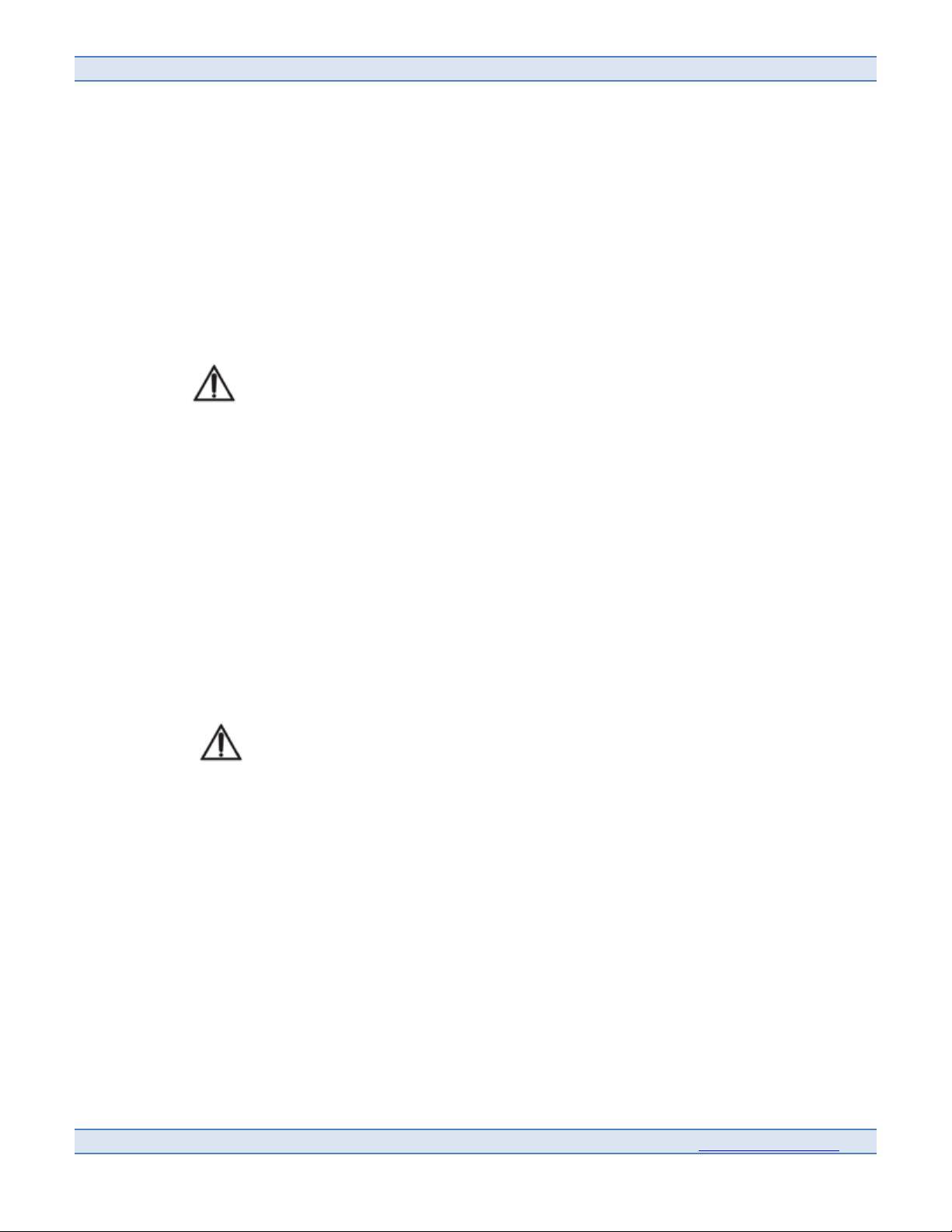
2.2.4 Filter O-Ring
Place a filter O-Ring (15 are supplied with the unit) into the groove in the filter adapter of each station.
This O-Ring ensures the disposable filters seal to the unit during a test.
The o-ring is not a disposable item and can be reused in multiple tests.
2.2.5 Exhaust Duct
A hose adapter with a diameter of approximately 4" should be placed around the SPE-Express exhaust
duct and connected to a fume hood or other available exhaust ducting.
The exhaust duct with fan may be interchanged between the two sides of the unit depending on your
venting preference. To switch the exhaust fan and ducting to the alternate side of the unit:
•
Use a 5/64" Allen wrench to remove the 4 screws on each of the two side panels.
•
The exhaust fan will be plugged to a cable within the internal channel of the unit. Remove the
exhaust fan plug from the cable receptacle.
•
Plug exhaust fan plug into the cable receptacle on the alternate side of the unit.
•
Replace 4 screws into each of the two side panels. Care should be taken to fully insert the cable
and wiring into the internal channel in order to prevent tangling the wiring into the fan.
Tangling the wires in the blades will cause a fan fault in the software and prevent the Operator
Test Screen from running.
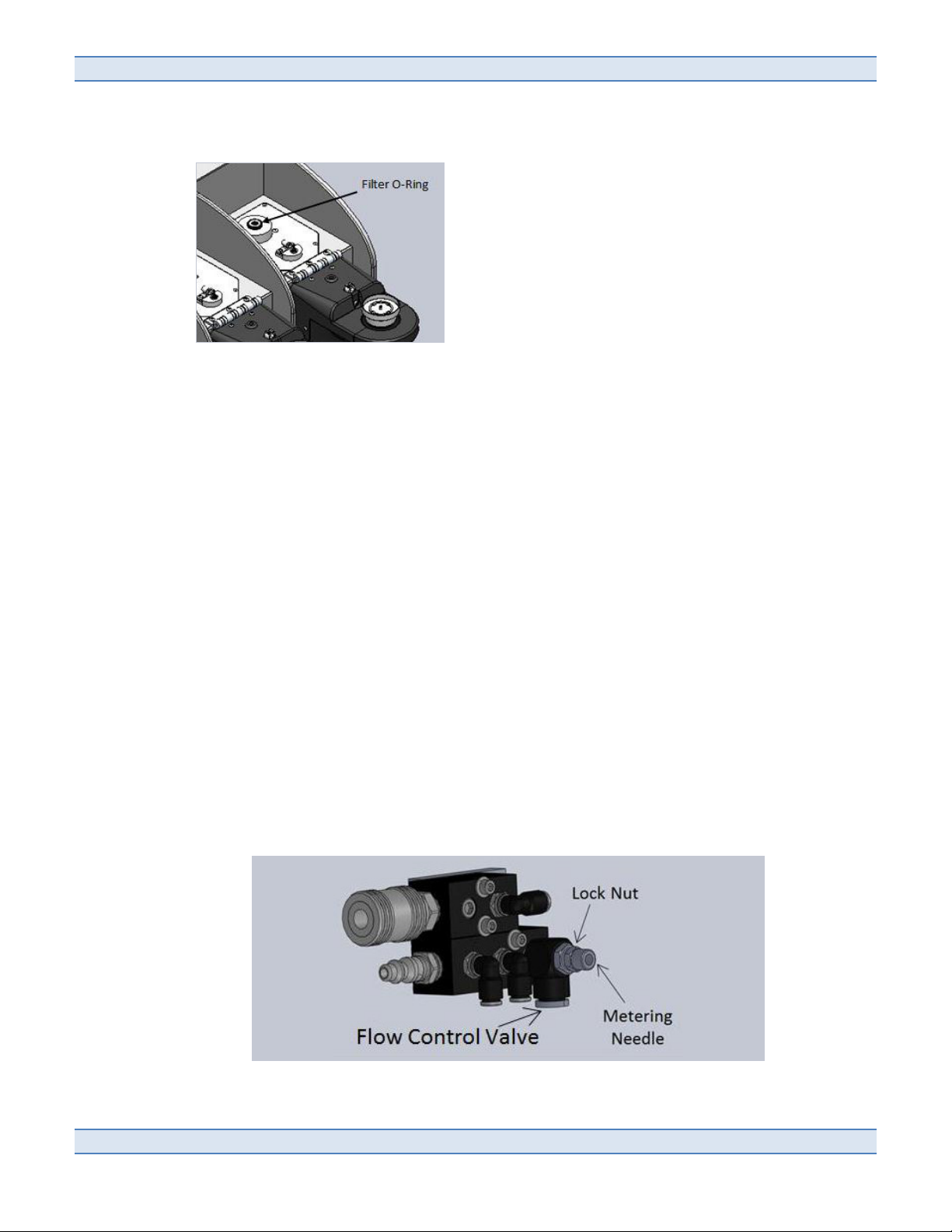
2.2.6 Flow Control Valve
A flow control valve is located within the SPE-Express unit which can be adjusted to supply a portion of the
Nitrogen source into the electronics chamber. The flow control valve is shipped set in the OFF position.
Page 12

SPE$Express*Operation*and*Instruction*Manual*!
*
www.envexp.com*****!
!
""!
If the unit is in a highly acidic or corrosive environment it is recommended that the flow control valve be
turned on. Note that when the flow control valve is on it will continue to supply Nitrogen as long as the
source Nitrogen is supplied to the back of the unit even if power is off. To adjust the flow control valve:
•
Ensure the SPE-Express power switch is in the OFF position.
•
Remove supply pressure from the unit by unfastening the supply hoses on the back of the unit.
•
Remove the back cover of the unit by unscrewing the thumbscrews.
•
Locate the flow control valve on the middle wall of the unit. It will be within the right fluids
chamber and has a tube which connects to a barb within the wall leading to the left electronics
chamber.
•
Loosen the lock nut on the front of the valve and adjust the metering needle counterclockwise
using a 3/32" Allen wrench. The valve SHOULD NOT be adjusted past a ¾ turn counterclockwise.
•
Tighten the lock nut toward the body of the valve to reduce the probability of unwanted
adjustment.
•
Replace the back cover of the SPE-Express unit with the thumbscrews.
•
Reattach the Nitrogen supply hoses.
2.2.7 Connecting Two Units
When operating two SPE-Express units from one computer use the G8050 Dual Unit Assembly Kit to make
the following modifications. The kit includes an additional reagent tubing kit and a dual unit coupler
panel.
•
Reagent Tubing – This kit will attach to the standard reagent tubing kit, and includes a “Y”
connector to attach both units. Follow the instructions in 2.2.2 to connect each of the three ends
to the standard reagent tubing kit and the instruments.
•
Exhaust Port and Fan – Both instruments must have the same exhaust fan/outlet configuration.
Use the dual unit coupler panel to connect the two units together. Use a 5/64" Allen wrench to
remove the blocking cover that is between the two units. Attach the dual unit coupler panel in
place of the removed blocking cover. Slide the two units together so that the exhaust from the
second unit is inside the dual unit coupler.
Additional Steps:
•
USB Cable – Connect each SPE-Express to the computer using a separate USB cable to a separate
USB port on the computer. Do not use USB cables longer than 10 feet.
•
Nitrogen Source – Both units can be run from a single nitrogen source. Use a “T” fitting (not
included) to split the line to provide a connection to each instrument. Only one unit should be
used to supply nitrogen to the reagents. The other unit should have this connection left unused.
•
If the software previously operated a single unit you must rerun the Configuration option in order
to set up for two units. Always use the system on the left as unit 1 and the system on the right as
unit 2.
!
!
Page 13

Environmental*Express,*Inc.!
!
*****800.343.5319/843.881.6560!
!
"#!
2.3 Setting Up the SPE-Express Software
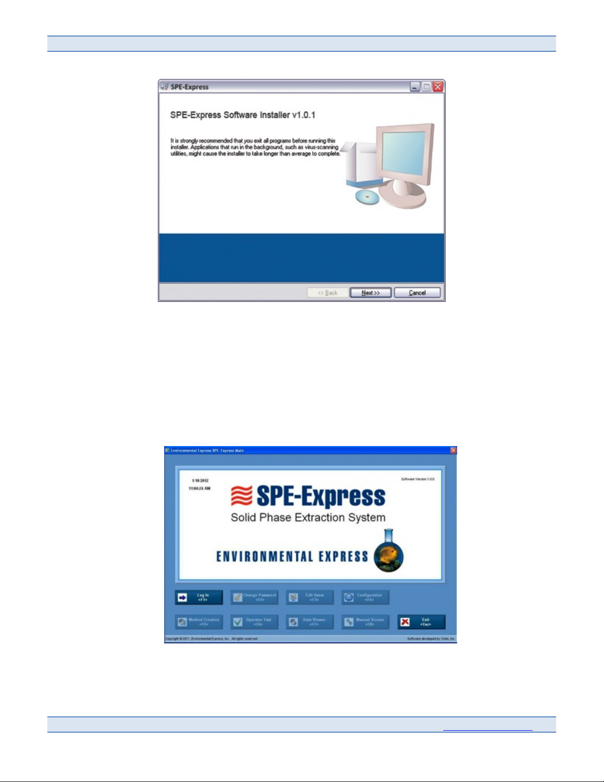
To set up your software, insert the Flash Drive provided and follow the screen prompts.
Click on the SPE-Express Installer file to start the script.
•
This "installation in progress" screen will appear. This window must stay open throughout the
program installation.
•
The script will install the USB to Serial Converter driver from the FTDI Software Folder. This
"installing driver" command prompt will appear.
Page 14
SPE$Express*Operation*and*Instruction*Manual*!
*
www.envexp.com*****!
!
"$!
•
After the driver is installed a prompt for National Instruments software will appear.
This installs the SPE-Express program and NI Software from the NI Software folder.
o
Navigate through the windows by pressing the "Next" button to install the software
o
After the software Is installed a shortcut to the SPE-Express Program will appear on the
Desktop
•
After installation is complete, restart the computer.
Welcome to the Environmental Express SPE-Express Software.
•
“Log In/Log Out”: Press to open the Log In dialog box.
•
“Exit”: Press to exit the SPE-Express software, or press the Escape key.
•
The date and time is shown in the upper left hand corner.
•
The software version is shown in the upper right hand corner.
Page 15

Environmental*Express,*Inc.!
!
*****800.343.5319/843.881.6560!
!
"%!
Keyboard shortcuts are available for each of the nine options on the SPE-Express Main Screen:
•
“Log Out”: Press to log out, or press the End key.
•
“Change Password”: Press to change your password, or press the F2 key.
•
“Edit Users”: Press to edit users, or press the F3 key.
•
“Configuration”: Press to launch the system configuration utility, or press the F4 key.
•
“Method Creation”: Press to launch the method creation screen, or press the F5 key.
•
“Operator Test”: Press to launch the operator test screen, or press the F6 key.
•
“Data Viewer”: Press to launch the data viewer screen, or press the F7 key.
•
“Manual Screen”: Press to launch the manual interface screen, or press the F8 key.
•
“Exit”: Press to exit the program, or press the Escape key.
2.3.1 Log-In Screen
To Log In:
•
Press the “Log In” button on the Environmental Express SPE-Express Main Screen, or press F1.
•
Enter your valid user name in the “User Name” field. Default user name is admin (all lower case).
•
Enter your valid password in the “Password” field. Default password is admin (all lower case).
•
“OK”: Press to log in or press the Enter key.
•
“Cancel”: Press to exit, or press the Escape key.
2.3.2 Change Password Screen
•
Press “Change Password” on the Main Screen or press F2.
•
Enter your old password in the “Old Password” field.
•
Enter your desired new password in the “New Password” field.
•
Re-enter your new password in the “Confirm New Password” field.
Figure 6
Figure 6
Figure 7
Page 16

SPE$Express*Operation*and*Instruction*Manual*!
*
www.envexp.com*****!
!
"&!
•
Press “OK” to accept the password change, or press the Enter key.
•
Press “Cancel” to exit, or press the Escape key.
2.3.3 Edit Users Screen
This feature allows the operator to add and delete user profiles and make changes to user profiles.
The screen lists current users and their permission levels.
There are three permission levels:
•
Operator: Method Creation, Change Password, Operator Test Data Viewer
•
Maintenance: Configuration, Manual Screen, Data Viewer, Operator Test, Change Password
•
Administrator: Permission to all seven levels (The only one with privileges to Edit Users)
The software includes default Maintenance and Operator users. The usernames are maintenance with
maintenance as the password and operator with operator as the password.
Access this screen by selecting “Edit Users” on the Main screen or press F3.
•
Press “Add User” to add an additional user, or press F1
•
Select a user and press “Delete User” to delete a user, or press F2
•
Press “Edit User” to edit the information or permission level of a current user, or press F3
•
Press "Exit" to exit, or press the Escape key
Software Functions / Edit Users
Figure 8
Page 17

Environmental*Express,*Inc.!
!
*****800.343.5319/843.881.6560!
!
"'!
2.3.4 Add New User Screen
This feature allows you to enter a new user into the system.
•
Access this screen by selecting “Add User” on the “Edit User” screen, or press F1
•
Enter the new user's full name In the “Full Name” field
•
Enter the new user's desired “User Name” In the "User Name" field
•
Choose the new user's permission level using the arrows on the “Level” controls
•
Enter the new user's desired "Password" and "Confirm Password" fields
•
Press “OK” to confirm, or press the Enter key
•
Press "Cancel to exit, or press the Escape key
Software Functions / Edit Users
Figure 8
Figure 9
Page 18

SPE$Express*Operation*and*Instruction*Manual*!
*
www.envexp.com*****!
!
"N!
2.3.5 System Configuration Screen
Once logged in, a first time user of the program on a new system should configure the hardware. To do this
press the “Configuration” button on the Environmental Express SPE-Express Main Screen, or press F4 and
follow the directions below.
Use this feature to verify that the SPE-Express Hardware is configured properly.
•
Press the “Configuration” control on the Main Screen.
•
Ensure that all SPE-Express System(s) are disconnected from the computer before initiating the
configuration process.
In the event you have additional National Instruments hardware connected to the computer or configured in
Measurement Automation Explorer, contact technical support.
•
Press the “OK” button, or press Enter. Once the “OK” button is pressed, the user will see the prompt.
o
Ensure the SPE-Express system is powered.
o
Connect the SPE-Express system USB cable to the computer.
o
Press the "OK" button, or press Enter. The blue progress bar will appear.
o
As the utility ensures the correct configuration of the hardware, the blue bar will steadily move
upwards. One of two prompts will appear.
o
Press “OK” to continue, or press the Enter key
Page 19

Environmental*Express,*Inc.!
!
*****800.343.5319/843.881.6560!
!
"O!
If your Configuration Test fails contact Environmental Express Technical Support for assistance at
800-745-8218.
When the Configuration Utility has completed its cycle, the Device Names and Product names will be listed
in the fields provided.
If you are running one unit and add a second unit at a later time, you must rerun the Configuration Utility
in order for the software to function properly.
Figure 13 Figure 14
Figure 12
Page 20

SPE$Express*Operation*and*Instruction*Manual*!
*
www.envexp.com*****!
!
"P!
2.3.6 Method Creation Screen
Press the “Method Creation” button on the Environmental Express SPE-Express Main screen or press F5.
The Method Creation Screen allows the user to create specific method parameters for testing.
2.3.6.1 Pre-Rinse
In this area, the user may enter parameters for hexane pre-rinse.
Use the arrow controls to:
•
Enter the desired hexane pre-rinse volume in milliliters.
•
Enter the desired hexane pre-rinse soak time in seconds.
•
Enter the desired hexane siphon time in seconds.
•
Enter the desired number of hexane pre-rinses.
2.3.6.2 Disk Activation
In this area, the user may enter parameters for disk activation.
Use the arrow controls to:
•
Enter the desired methanol injection volume in milliliters.
•
Enter the desired methanol soak time in seconds.
2.3.6.3 Sample Filtration
In this area, the user may enter the filter drying time for sample filtration.
2.3.6.4 Elution
In this area, the user may enter parameters for the elution step. Use the arrow controls to:
•
Select the desired hexane spray volume in milliliters per spray.
Page 21

Environmental*Express,*Inc.!
!
*****800.343.5319/843.881.6560!
!
#Q!
•
Select the desired number of hexane sprays per rinse cycle.
•
Select the desired hexane drain time in seconds.
•
Select the desired number of rinse cycles.
•
Select the desired activated vacuum time in seconds.
•
Select the desired deactivated vacuum time in seconds.
•
Select the desired number of total vacuum cycles.
•
Select the desired vacuum dry time in seconds.
•
Select the desired nitrogen purge time in seconds.
When entering the “Hexane Spray Volume”, and the “Hexane Sprays per Rinse Cycle”, the total
hexane spray volume cannot exceed 30mL or drop below 9mL.The warning message will appear if
the requirements are not met.
When entering the “Hexane Spray Volume”, the “Hexane Sprays per Rinse Cycle”, and “Number of
Rinse Cycles” text box, the total hexane volume cannot exceed 120mL or drop below 27mL. The
warning message will appear if the requirements are not met.
2.3.6.5 Solvent Evaporation
The software will automatically calculate the hexane evaporation time based on the total amount
of hexane used in the method. This evaporation time will be added to the end of the test prior to
completion.
•
Press the “Load” button to import pre-created parameters into the system, or press the
F1 key.
•
Press the “Save” button to save the parameters shown, or press the F2 key.
•
Press the “Save As” button to save the parameters shown under a different file name, or
press the F3 key.
•
Press the “Print” button to print the parameters shown, or press the F4 key.
•
Press the “Exit” button to exit, or press the Escape key.
Figure 18
Figure 19
Figure 18
Figure 20
Figure 19
Page 22

SPE$Express*Operation*and*Instruction*Manual*!
*
www.envexp.com*****!
!
#"!
2.3.6.6 Method Parameter Specifications
Status Name Input Limits Description
Pre-Rinse Hexane Pre-Rinse Volume 10-20 mL Cleans system below sample bottle with specied amount of
hexane, allows hexane to soak and then siphons hexane to hexane
waste container.
Hexane Pre-Rinse Soak Time 30-120 seconds
Hexane Siphon Time 60-120 seconds
Number of Hexane Pre-Rinses 1-5 rinses
Disk Activation Methanol Injection Volume 10-20 mL Injects desired amount of methanol onto the lter and allows
methanol to soak into the lter.
Methanol Soak Time 60-120 seconds
Sample Filtration Filter Dry Time 10-20 minutes After the sample bottle has drained, the time the lter is allowed to
dry with vacuum prior to elution.
Hexane Rinse Parameters Spray Volume 3.1-30 mL/spray Volume of hexane used to spray the sample bottle.
Sprays per Rinse Cycle 1-10 sprays Number of sprays per rinse cycle
Total Spray Volume 9-30 mL Total volume of hexane used to spray the sample bottle during 1
rinse cycle. *Automatically updates to show the total hexane usage
during the bottle rinses based on the Total Spray Volume and the
Number of Rinse Cycles.
Drain Time 30-120 seconds Amount of time between each rinse cycle.
Number of Rinse Cycles 1-5 rinses The number of rinse cycles the system completes during elution.
Total Volume 27-120 mL The total volume of hexane used during the elution steps.
*Automatically updates to show the total hexane usage during the
bottle rinses based on the Total Spray Volume and the Number of
Rinse Cycles.
Vacuum Parameters Vacuum ON Time 10-20 seconds Pulsing ON/OFF of the vacuum within the glass chamber to remove
eluted hexane from the lter.
Vacuum OFF Time 5-20 seconds
Total Vacuum Cycles 5-10 cycles
Vacuum Dry Time 60-180 seconds Final vacuum duration to pull all remaining hexane into the glass
chamber.
Nitrogen Purge 3-120 seconds Application of nitrogen to push all hexane from the glass chamber
to the evaporation pan.
*automatically calculated
*automatically calculated
Page 23

Environmental*Express,*Inc.!
!
*****800.343.5319/843.881.6560!
!
##!
2.4 Flushing the System
Once the user has configured the new hardware, the user will see nine active options on the main screen.
The next step is to perform a System Flush.
The System Flush will include performing a “Station Flush” for each of the 3 stations. The Flush will
ensure all air is removed from the reagent lines and that all hardware is clean. The instructions for the
“Station Flush” are located in section 2.4 and 3.2.2.
•
Press “Flush Station”.
•
Once “Flush Station” is pressed, a prompt will appear. Press the radio buttons to confirm that the
following steps have been completed:
o
Install a new filter disk
o
Install a clean, empty sample bottle
o
Ensure that the bottle assembly is latched in the upright position.
o
Ensure an aluminum evaporating pan is on the heater block (Note: there is no need to
pre-weigh to pan)
Page 24

SPE$Express*Operation*and*Instruction*Manual*!
*
www.envexp.com*****!
!
#$!
o
Remove the spring clamp and place the sliding glass chamber into the down position
o
Install a new drying cartridge
•
Press “Next”.
•
Once “Next” is pressed, a prompt will appear. Press the radio buttons to confirm the following steps
have been completed:
o
Raise sliding glass chamber into upper position
o
Ensure that the sliding glass chamber is properly sealed (Note: after “Next” was pushed,
vacuum pressure is applied to the chamber to help seal the glass chambers together)
o
Install spring clamp after seal is made
o
Ensure door is closed
Page 25

Environmental*Express,*Inc.!
!
*****800.343.5319/843.881.6560!
!
#%!
3.0 System Operation
Sample Setup
The illustrations below show the proper configuration of the SPE-Express system and consumables.
Care should be taken not to allow foreign debris to enter into the Filter Adapter as this could cause damage to the valve.
It is recommended that the rubber plug supplied with the unit be used to plug the Filter Adapter when the unit is in long
periods of non-use.
Page 26

SPE$Express*Operation*and*Instruction*Manual*!
*
www.envexp.com*****!
!
#&!
3.1 Operator Test Screen
The Operator Test screen allows the user to operate the SPE-Express.
The Exhaust and Vent fans will automatically run when the software is in the Operator Test Screen
3.1.1 Pre-Test Interface
•
Select the tab of the desired station in the upper left corner of the screen.
•
Press the Select Method button to browse existing methods.
•
Select the desired method.
•
Press View Method to view the selected method parameters.
•
Enter the Sample ID number.
•
Enter the Sample Volume in milliliters.
The user may enter notes at any point in time in the Notes text box.
3.1.2 Station Status
This area allows the user to see the status of the door switch, latch, and the station temperature.
Page 27

Environmental*Express,*Inc.!
!
*****800.343.5319/843.881.6560!
!
#'!
3.1.3 Testing Status Summary
This area allows the user to see the status of each station during testing. The bars will indicate the:
•
Pre-rinse
•
Disk Activation
•
Sample Filtration
•
Elution
•
Solvent Evaporation
Only the status of stations in a unit that are in use will be displayed. For example, in the screen shot page 25,
only stations one through three are displayed, because a second unit is not connected to the computer.
3.1.4 Test Control and Status
This area allows the user to perform tasks and receive testing information.
Test Information shows the specific notes to update the user about the progress of the test such as
“Injection Methanol” or “Drying Filter Pad”.
Elapsed Time shows a timer for the duration of the test.
These status indictors will also display information for the previous test if two tests are in progress on the
same station.
3.1.5 Bottle Rack Status
This area allows the user to see the fluid levels of the various chemicals in the Bottle Rack, and the status
of the Bottle Rack itself.
The Bottle Rack Status is only active when the optional Smart Bottle Rack is equipped. The Smart Bottle Rack
is sold separately.
Page 28

SPE$Express*Operation*and*Instruction*Manual*!
*
www.envexp.com*****!
!
#N!
3.2 Operating A Test
3.2.1 Starting a Test
•
Press “Start Test”.
•
Ensure that the filter O-Ring is in place (page 10).
•
Ensure that the bottle adapter O-Ring is within the groove of the bottle adapter prior to installing the
sample bottle in the unit.
CAUTION: cracking of the glass sample bottle can occur if the bottle O-Ring is not in place.
•
Once “Start Test” is pressed, a prompt will appear. Press the radio buttons to confirm the following
steps:
o
Install a new filter disk mesh side down (The filter cup should be firmly pressed onto the
injection head.)
o
Install a sample bottle (The sample bottle should be screwed hand tight into the bottle
adapter.)
o
Ensure that the bottle assembly is latched in the upright position (An O-Ring should be
present in the groove of the filter adapter. The filter cup will rest on this O-Ring when the
swinging assembly is in the upright position.)
o
Place a new pre-weighed aluminum evaporating pan on the heater block
o
Remove the spring clamp then lower the sliding glass chamber into the down position
o
Install a new drying cartridge (The drying cartridge should be slid onto the internal nozzle of
the upper glass chamber.)
•
Then press “Next”.
•
Once “Next” is pressed, the vacuum will start and a second Pre-Test Checklist will appear as shown,
Test Checklist. Press the radio buttons to confirm the following steps:
Page 29

Environmental*Express,*Inc.!
!
*****800.343.5319/843.881.6560!
!
#O!
o
Raise the sliding glass chamber into the upper position
o
Ensure that the sliding glass chamber is properly sealed (When the “Next” button is pushed,
vacuum pressure is applied to the glass chamber to help seal the glass chambers together.)
o
Install a spring clamp after seal is made
o
Ensure doors are closed.
•
Select your next step:
o
Press “Ready” <Enter> to begin the test.
o
Press “Back” to turn off the vacuum and return to the previous prompt prior to beginning the
test.
o
Press “Exit” to return to the Operator Test screen.
o
Once you press "Ready" the software will begin monitoring test progress.
•
The software automatically calculates the evaporation time based on the amount of hexane used
during the test. Following evaporation the software will chime and a prompt will alert you that the
test has been completed.
•
The drying cartridge and filter assembly can be discarded at this point.
The filter O-Ring may have a tendency to stick to the filter, so care should be taken not to discard the
O-Ring.
•
If the software detects a malfunction with the test or hardware during testing, the test may abort
automatically as a safety precaution. In the event this occurs, the Test Info will show the reason the
software initiated the abort (this message will also appear in the test data).
For safety reasons, the door must remain closed and the swinging front assembly must remain in the upper
latched position during testing. If the door or ball valve is unlatched, the software will automatically abort
the test.
Page 30

SPE$Express*Operation*and*Instruction*Manual*!
*
www.envexp.com*****!
!
#P!
3.2.2 Flushing a Station
•
Press “Flush Station”.
•
Once “Flush Station” is pressed, a prompt will appear. Press the radio buttons to confirm that the
following steps have been completed:
o
Install a new filter disk
o
Install a clean, empty sample bottle
o
Ensure that the bottle assembly is latched in the upright position.
o
Ensure an aluminum evaporating pan is on the heater block (Note: there is no need to preweigh to pan)
o
Remove the spring clamp and place the sliding glass chamber into the down position
o
Install a new drying cartridge
•
Press “Next”.
•
Once “Next” is pressed, a prompt will appear. Press the radio buttons to confirm the following steps
have been completed:
o
Raise sliding glass chamber into upper position
o
Ensure that the sliding glass chamber is properly sealed (Note: after “Next” is pushed, vacuum
pressure is applied to the chamber to help seal the glass chambers together)
o
Install spring clamp after seal is made
o
Ensure door is closed
•
Press “Ready” <Enter>. The system flush will begin.
• Press “Back” <F1> to turn off the vacuum and return to previous prompt prior to beginning the flush
Page 31

Environmental*Express,*Inc.!
!
*****800.343.5319/843.881.6560!
!
$Q!
• Press “Exit” <Esc> to return to the Operator Test screen.
3.2.3 Draining a Station Manually
If a test is aborted prior to or during the bottle drain portion of the test the “Drain Station” button may be
pressed which will allow the sample bottle to drain into the waste container.
Caution: if the test aborted during the bottle drain procedure, sample water may be caught between the filter
pan and the ball valve. If this water is not removed by initiating the drain function it could leak while
unlatching the swinging assembly.
•
Press “Drain Station”.
•
A prompt will appear to confirm the initiation of the draining procedure.
•
Press “Ready”. The pathway to the waste container and ball valve directly below the bottle will open
allowing the sample water to drain.
•
Press “Exit” to return to the Operator Test Screen without initiating the Drain procedures.
•
Once “Ready” is pressed prompt will be removed and the “Draining Station” button on the Operator
Test screen will display red to indicate that this feature is on.
•
Press “Draining Station” to conclude the draining procedures.
3.2.4 Cleaning a Station Manually
•
If the hardware within the swinging assembly becomes clogged during a test the Manual Clean may be
used to clean the system without having to exit the Operator Test Screen. This allows a clogged station
to be cleaned without interrupting tests on other stations.
•
Before using a manual clean it is recommended to perform a Station Drain until all residual water has
entered the waste container.
•
Swing the assembly into the lowered position and leave the filter in place.
•
Press the Manual Clean button.
Page 32

SPE$Express*Operation*and*Instruction*Manual*!
*
www.envexp.com*****!
!
$"!
•
A prompt will appear with a ball valve control switch, the switch may be toggled to open and close the
ball valve within the swinging assembly.
3.2.5 Aborting a Test
•
Any procedure can be aborted at any time by pressing either the Abort Station or Abort All.
•
An “Abort Station” button will appear at the lower left hand corner of the Operator Test screen while
performing a test, system flush or drain. This button will stop all procedures on that particular station
and remove power from the station components as a safety precaution.
•
The “Abort All” <End> is always present at the lower right hand corner of the screen. This button may
be pressed at any time to stop all procedures on all stations simultaneously and power will be
removed from all three station components.
•
After either Abort button is pressed the “Reset Station” button must be pressed to restore power to the
unit and continue normal operation.
•
In a case of emergency where the Abort buttons cannot be pressed the USB cord may be unplugged
disconnecting the SPE-Express from the computer. This will remove power from all hardware. The
unit may require a System Configuration following this procedure.
•
With the ball valve in the open position, remove the filter and use DI water to rinse clogged media
back into the sample bottle. Never insert foreign objects or fingers into ball valve.
•
After cleaning, toggle the switch to the Off position and close the prompt. The sample bottle can now
be removed.
3.3 Operating Multiple Samples on One Station
A new test may be started on any station while that station’s previous test is in completing “Elution” and
“Evaporation” procedures.
Once “Start Test” button reappears in the Operator Test screen, the swinging arm assembly can be unlatched and
the sample bottle and filter assembly can be removed. The station door should not be opened until the software
has completed evaporation, as this will cause the software to abort the previous test.
•
Press the “Start Test” button.
•
Once “Start Test” is pressed, a prompt with appear. Press the radio buttons to confirm the following
steps have been completed:
Page 33

Environmental*Express,*Inc.!
!
*****800.343.5319/843.881.6560!
!
$#!
o
Ensure doors remain closed
o
Install a new filter disk
o
Install a sample bottle
o
Ensure bottle assembly is latched in the upright position.
•
Press “Ready” for the second test to begin or press “Exit” to return to the Operator Test screen if
subsequent samples are not scheduled.
•
Once the previous test completes the software will alert you with a prompt. The second test will not
proceed past the filter drying step until the previous test is completed. Press the radio buttons to
confirm that the following steps have been completed:
o
Remove the aluminum evaporating pan from the heater block
o
Place a new pre-weighed aluminum evaporating pan on the heater block
o
Remove spring clamp then lower sliding glass chamber into the down position
o
Remove and discard the drying cartridge
o
Install a new drying cartridge
•
Press “Next” to continue to the next prompt. Press the radio buttons to confirm that the following
steps have been completed:
Page 34

SPE$Express*Operation*and*Instruction*Manual*!
*
www.envexp.com*****!
!
$$!
o
Raise sliding glass chamber into upper position.
o
Ensure that the sliding glass chamber is properly sealed.
o
Install spring clamp after seal is made.
o
Ensure doors are closed.
•
Press “Ready” to continue the second test.
•
Press the “Abort Test Station” button to stop all procedures within the station and to remove power
from all station components.
•
Press the “Abort All” <End> button to stop all three station procedures and to remove power from all
three station components.
3.4 Operating Multiple Stations
All three stations may be run simultaneously by toggling between the designated station tabs in the left hand
corner of the Operator Test Screen.
The software requires that the user acknowledge any prompt appearing while running station procedures prior to
returning to the Operator Test screen.
3.5 Operating Two Units
All six stations may be run simultaneously by toggling between the designated station tabs in the left hand corner of
the Operator Test Screen. Unit 1 will always be the unit on the left and unit 2 will be the unit on the right. The
stations in unit 1 will retain the identification numbers 1-3 while the stations in unit 2 will be reassigned as stations
4-6.
Page 35

Environmental*Express,*Inc.!
!
*****800.343.5319/843.881.6560!
!
$%!
3.6 Manual Operation
The Manual Interface Screen allows for the control and manipulation of up to 6 stations (3 stations/unit, up to 2
units total). Only users with the permission level of “Administrator” or “Maintenance” are allowed to access this
screen, due to the potential of serious safety hazards. Press the “Manual Screen” button or press F8 on the SPEExpress Main Screen. The following directions apply to all available station tabs located in the upper left hand
corner of the screen.
The software will show the following message when opening the manual screen:
WARNING: Ensure that the “Nitrogen-To Reagents” line is disconnected before using this utility. Otherwise, danger
to personnel and damage to equipment could result.
3.6.1 Solenoid Control Interface
In this area, the user may manipulate the solenoids for the various liquids and gases used by the station.
Press the corresponding buttons to power these solenoids:
•
Hexane Bottle Rinse Solenoid
Page 36

SPE$Express*Operation*and*Instruction*Manual*!
*
www.envexp.com*****!
!
$&!
•
Methanol Rinse Solenoid
•
Deionized Water Rinse Solenoid
•
Hexane Chamber Rinse Solenoid
•
Vacuum Control Solenoid
•
Nitrogen Pressure Solenoid
The user may control how long one of the above solenoids is powered. Toggle the Timed Control Switch to
Auto.
•
Enter the desired time that the solenoid will remain active.
•
Press the button corresponding with the solenoid to be activated.
•
The Elapsed Time will count up to time completion and then deactivate the solenoid.
The user may power any one of the 3-Way Solenoid Valve Interface solenoids (the “Hexane Waste Sol”,
“Water Miscible Waste Sol” or “Eluted Sample Path Sol” by pressing the button corresponding with the
desired solenoid (cannot be completed automatically).
The user may power the sample release solenoid by pressing the corresponding button (cannot be
completed automatically).
3.6.2 Ball Valve
In this area the user can control the ball valve. Press the switch to open or close the ball valve.
3.6.3 Status Indicators
In this area, the user may see the current status of the door and latch. Press the switch to power the latch
and door switch.
3.6.4 Main Fans
In this area, the user may see the current status of the vent and exhaust fan. Press the “Main Fans” switch
to power the vent and exhaust fans
3.6.5 Sensor Chart
•
Press the Power Enable button at the lower left hand corner of the graph to turn on the
station sensor.
•
The graph will update the sensor status with respect to time. The graph will display one if
the sensor is in the ON state (the sensor will have an orange light near the cable). This ON
state should be seen when sample water is draining to the waste container. The graph will
display zero if the sensor is in the OFF state.
The ON/OFF states require occasional calibration to maintain accuracy. See Sensor Calibration
instructions, Section 5.5.
•
Press the power button again to turn off the station sensor.
!
!
Page 37

Environmental*Express,*Inc.!
!
*****800.343.5319/843.881.6560!
!
$'!
3.6.6 Temperature Control
In this area, the user may control and view the temperature of the evaporating platform.
•
Use the arrow controls to manipulate the temperature setpoint.
•
Press the “Enable Temp Control” button to enable or disable the closed loop Watlow®
temperature control.
3.6.7 Bottle Rack Status (if purchased separately)
In this area, the user may see the fluid levels of the:
•
Deionized Water
•
Methanol
•
Hexane
•
Waste Water
•
Hexane Waste
3.6.8 Abort
Press “Abort” in case of an emergency to immediately stop a station, or press the End key.
3.6.9 Exit
Press “Exit” to exit the screen, or press the Escape key.
Page 38

SPE$Express*Operation*and*Instruction*Manual*!
*
www.envexp.com*****!
!
$N!
4.0 Data Recovery
After it is installed, the software creates a folder named SPE-Express Test Data. Data for each test run will automatically be
written to an individual file within that folder.
There are two ways to access Test Data:
• The Data Viewer within the SPE-Express software
o Click the “Data Viewer” button on the Main Screen, or press the “F7” key on your computer. You can
also click “View Data (or F1) in the Operator Test Screen
o Once in the Data Viewer, press “F1” or click “Load” to select a test data file
o Individual files can be printed by pressing “F2” or clicking “Print”
o Press “Esc” or click “Exit” to close the Data Viewer
• Opened using Excel from the “SPE-Express Test Data” folder created when the software is installed
o This folder can be found on the user’s C drive within the SPE-Express folder created during installation
of the software.
o Test files are automatically saved by date_time_sample ID #. The operator can arrange the files within
the folder to their liking
o Operator can edit the files in Excel to include pre-and post-test pan weights
Page 39

Environmental*Express,*Inc.!
!
*****800.343.5319/843.881.6560!
!
$O!
5.0 Care and Maintenance
5.1 Removing and Cleaning Lower Glass Chamber
Removing and cleaning the glass chamber in the SPE-Express should be part of your routine maintenance in
maintaining a clean instrument. The frequency of the cleaning will be dependent on the number and types of
samples analyzed and should be determined by each individual end-user.
•
Unscrew the hexane line coming out of the side-arm of the chamber by unscrewing the black nut.
An o-ring is located in this ring so be careful not to lose it. This line will be the front line from the
side of the chamber.
•
Unscrew the Nitrogen line coming out of the side-arm of the chamber by unscrewing the black
nut. An o-ring is located in this ring so be careful not to lose it. This line will be the back line from
the side of the chamber.
•
Loosen the black nut at the bottom of the chamber above the sample release solenoid. This ring
will unscrew by twisting it clockwise when viewed from above.
•
Using a 5/32" Allen wrench, unscrew the 2 screws in the clamp behind the glass chamber. Remove
the clamp and screws together once the screws are completely loosened.
•
Pull the glass chamber out.
•
Clean with DI Water to remove debris.
•
Rinse with acetone to remove all traces of water.
•
Rinse with hexane to clean the reservoir and allow it to completely dry.
5.2 Removing and Cleaning Barb Fittings
•
Remove the barb fittings from the top and bottom of the solenoid using a 7/16" wrench.
The tube will stay on the top fitting during cleaning.
•
Clean the DI water to remove debris. Do NOT clean with acetone.
•
Rinse with hexane to clean and remove excess water.
•
Allow fittings to dry completely.
5.3 Cleaning the Sample Release Port
The Sample Release Port should be cleaned any time the glass chamber is cleaned. Follow the instructions below:
•
Place an empty pan below the Sample Release Port.
•
In the manual screen in the SPE-Express software, click on the “Sample Release Solenoid” button.
CAUTION: if the solenoid remains on for an extended period of time it will become hot.
•
This will open the valve so the port can be cleaned.
•
Using a squirt bottle, squirt DI Water through the top of the sample release valve to remove any
debris that may be present.
•
Squirt acetone through the top of the sample release valve to remove any DI Water.
•
Blow clean filtered air or Nitrogen through open valve to dry completely. (Do NOT use any
unfiltered air for this as particulates can cause damage to the valve).
•
Click the “Sample Release Solenoid” in the manual screen in the SPE-Express software to close the
valve.
Page 40

SPE$Express*Operation*and*Instruction*Manual*!
*
www.envexp.com*****!
!
$P!
5.4 Replacing the Lower Glass Chamber
•
Replace barb fittings into the upper and lower solenoid ports with a 7/16" wrench (do not overtighten fittings).
•
Place the bottom port of the lower glass chamber around the tube on the sample release solenoid
and hold in place.
•
Replace the bottom black nut to attach the sample release port to the lower glass chamber.
•
Using a 5/32" Allen wrench attach the clamp behind the lower glass chamber by screwing the 2
screws all the way down (hand tight) and then backing the screws one rotation. DO NOT
OVERTIGHTEN THE SCREWS! The lower glass chamber should still be able to slightly wiggle.
•
Attach the Nitrogen line to the back side arm of the glass chamber by inserting the tube into the
back side of the black nut and then into the O-ring. Insert the tube into the back port of the glass
chamber approximately 1 inch and tighten the nut to the glass.
•
Attach the Hexane Chamber line to the front side arm of the glass chamber by inserting the tube
into the back side of the black nut and then into the O-ring. Insert the tube into the front port of
the glass chamber approximately 1 inch and tighten the nut to the glass.
•
In the manual screen in the SPE-Express software, turn on the vacuum by pressing the “Vacuum
Solenoid” button. Push the lower glass chamber up to the upper glass chamber and slowly
remove support from the lower glass chamber (be careful not to allow the lower glass chamber to
fall freely). If the lower glass chamber has been re-attached correctly it will stay seated on the
upper glass chamber and the glass clamp can be put into place. If the lower glass chamber has
not been re-attached correctly it will not stay seated on the upper glass chamber and needs to be
re-adjusted (try slightly loosening the glass clamp screws and check that all nuts are fully
tightened). Check the tightness of the lines to insure there are no leaks.
5.5 Recalibrating the Fluid Sensor
The sensor on the back wall of the each station is used to detect when the sample bottle is dry enough to proceed
with elution procedures automatically during the test. Periodic recalibration of the sensor is recommended to
ensure accurate operation. To complete the recalibration procedures:
•
From within the station, unscrew the nut within the upper glass chamber plug (this is the nut
which connects the tube from the station valve to the upper glass chamber).
•
Remove the top panel with filter adapter and latch by unscrewing the 4 panel screws using a
5/64" Allen wrench.
•
Twist the luer fitting of the waste lines clockwise and remove the tubing from the valve. (This step
may also be completed prior to removing the upper panel).
•
Unplug the 4 plugs connecting the wiring from the panel valve and latch from the receptacles
along the right wall of the station.
•
Set the upper panel assembly aside. Care should be taken not to allow foreign debris to enter into
the filter adapter, use the rubber plug provided with the unit if possible.
•
Unscrew the left sensor nut on the body of the sensor (toward the orange sensor head) so that the
sensor can slide back from the water miscible waste line tube (far enough to switch out the tube).
•
Remove water miscible waste tubing from the tubing holder on the mount.
Page 41

Environmental*Express,*Inc.!
!
*****800.343.5319/843.881.6560!
!
%Q!
•
Insert the sensor calibration tube provided with the SPE-Express unit (the tube should contain a
consistent column of DI water with a pH<2) and push the orange head of the capacitive sensor up
flush with the tube.
•
Ensure the sensor has power by entering into the Manual Screen and pressing the Sensor Power
Control below the graph.
•
Using a long pointed tool (such as a #1 screwdriver), press and hold the sensor “ON” button
(button closest to the back of the chamber). Confirm that the orange sensor indicator light is
blinking slowly. When the indicator light changes from slow blinking to a quick blinking
(approximately 6 sec) the ON state calibration is complete.
•
Remove the sensor calibration tube. Ensure that the water miscible waste tube is dry and reinstall the tube into the tube holder within the mount.
•
Push the orange sensor face onto the tube holder and tighten the sensor body nuts.
•
Using a long pointed tool (such as a #1 screwdriver) press and hold the sensor “OFF” button
(button is closest to the front of the station). Confirm that the sensor indicator light is blinking
slowly. When the indicator light changes from slow blinking to a quick blinking (approximately 6
sec) the OFF state calibration is complete.
•
Re-install the upper panel assembly by attaching the 4 wiring connectors (the color markings on
the connectors are the same for each pair of plug and receptacle to allow for easy matching of the
connectors and the wire numbers on either side of the plug and receptacle should also match).
•
Insert the female luer fittings of the water miscible waste and hexane waste tubes into the left
and right male luer fittings of the valve respectively. Tighten the fittings by turning the blue
portion counterclockwise.
•
Insert and tighten the nut of the eluted sample path from the bottom port of the valve into the
plug in the upper glass chamber. Re-install the 4 panel mount screws using a 5/64" Allen wrench.
5.6 Changing the Bottle Adapters and Injection Heads
The SPE-Express unit is supplied with 3 bottle adapters (one per station) which allow for the connection of the
53mm Wide Mouth Packer and 3 injection heads (one per station) which accept the 47mm filter assembly. Optional
adapters are available for the SPE-Express which accept a variety of bottles including the 33 mm Boston Round, 70
mm wide mouth jar and the 89 mm wide mouth jar. A larger injection head which adapts to the 90 mm filter
assembly is also an available optional accessory. The following gives instructions for changing these accessories.
•
Complete this step only if the injection head is being changed: remove the 2 screws on either side
and the 1 screw in the front of the front cover of the swinging assembly using a 3/32" Allen
wrench. Pull cover straight out from the unit, set cover and screws aside. Unscrew the 3 reagent
lines from the injection head and pull air intake tube off of the barb in the injection head (the
injection head may need to be turned in order to access these ports, the set screws will need to be
loosened prior to turning the injection head, this is explain in the next step).
•
There are 3 metal set screws located around the outside of the bottle adapter/ injection head to
prevent free spinning. Using a 3/32" Allen wrench, remove these set screws and set aside (if one
of the set screws is not easily accessible due to being blocked by the cover or assembly it will not
require loosening).
Page 42

SPE$Express*Operation*and*Instruction*Manual*!
*
www.envexp.com*****!
!
%"!
•
Using the 2.25" wrench (provided with the SPE-Express unit) placed on the flat surfaces around
the bottle adapter/ injection head, loosen the bottle adapter/ injection head. (With the swinging
assembly in the down position the bottle adapter should be spun clockwise and the injection
head should be spun counterclockwise).
•
Replace with desired bottle adapter/ injection head by spinning onto the ends of the ball valve
and tighten with the 2.25" wrench. (With the swinging assembly in the down position the bottle
adapter should be spun counterclockwise and the injection head should be spun clockwise).
•
Insert the set screws into the 3 holes on the side of the bottle adapter/ injection head and tighten
with a 3/32" Allen wrench. (If one of the set screws is not easily accessible due to being blocked by
the cover or assembly it may be left loose).
•
Complete this step only if the injection head is being changed: replace the air intake line onto
the barb and tighten reagent injection lines into the designated ports. (The Hexane Bottle Rinse
tube MUST be in the center port. The Methanol line should be clockwise from the center port and
the DI Water line should be counterclockwise from the center port). Replace the front cover of
the swinging assembly and fasten with 3 screws with a 3/32" Allen wrench.
5.7 Detaching the Bottle Harness
If it is desired to disconnect the bottle harness from the SPE-Express unit the following steps should be followed to
ensure there is no leakage of chemicals. Note that this process should not be followed if there is a possibility that
the source lines within the bottle harness or unit are contaminated.
•
Remove the Reagents Pressure Hose from the SPE-Express unit. (This will allow the SPE-Express
components to retain pressure while the bottles and bottle harness are depressurized).
•
Loosen the caps on the n-Hexane, Methanol, and DI Water. DO NOT REMOVE CAPS FROM
BOTTLES.
•
Ensure there is a filter cup assembly in place on the swinging assembly and that the swinging
assembly is in the UP (LATCHED) POSITION.
•
Ensure the lower glass chamber is seated on the upper glass chamber and secured with the glass
clamp.
•
Enter the Station 1 tab of Manual Screen in the SPE-Express software.
•
Click to open the “Hexane Waste Sol”.
•
Ensure that all n-Hexane waste has entered the Hexane waste container and click to close the
“Hexane Waste Sol”.
•
Click to open the “Water Miscible Waste Sol”.
•
Ensure that all water miscible waste has entered the water miscible waste container and click to
close the “Water Miscible Waste Sol”.
•
Click the “Hexane Chamber Rinse Sol” to drain the hexane from the chamber rinse line back to
the n-Hexane source bottle.
•
Click the “Nitrogen Pressure Sol” button.
•
Once the n-Hexane is evacuated from the line (Nitrogen will be heard entering the n-Hexane
source bottle), close the Hexane solenoid by pressing “Hexane Chamber Rinse Sol”.
•
Click to open the “Eluted Sample Path Sol”.
Page 43

Environmental*Express,*Inc.!
!
*****800.343.5319/843.881.6560!
!
%#!
•
Click to open the “Hexane Bottle Rinse Sol”.
•
Once the n-Hexane is evacuated from the line (Nitrogen will be heard entering the n-Hexane
source bottle), close the Hexane solenoid by pressing “Hexane Bottle Rinse Sol”.
•
Click to open the “Methanol Rinse Sol”
•
Once the Methanol is evacuated from the line (Nitrogen will be heard entering the Methanol
source bottle), close the Methanol solenoid by pressing “Methanol Rinse Sol”.
•
Click to open the “DI Water Rinse Sol”
•
Once the DI Water is evacuated from the line (Nitrogen will be heard entering the DI Water source
bottle), close the DI Water solenoid by pressing “DI Water Rinse Sol”.
•
Repeat this process in the Manual Screen for all 3 stations to ensure all chemicals have been
evacuated from the tubing lines.
•
Carefully remove the tubes within the bottle caps from the sources bottles.
Caution: the tubes may contain some residual chemical.
•
Remove the top 3 fittings from the back of the manifold using the Fastener Tool supplied with the
unit.
•
Remove the bottom 3 tubes by twisting the blue portion of the luer fitting clockwise.
•
The bottle harness should be stored in a dry environment which has low risk of contact with
contamination.
Page 44

SPE$Express*Operation*and*Instruction*Manual*!
*
www.envexp.com*****!
!
%$!
PARTS LIST:
G8000 Base 3-Station
ACCESSORIES:
ABP110 Reagent Rack
G3070 20-Liter Waste Carboy
G8018 Bottle Adapter Assembly - 33mm (w/O-Ring Dash Number 119)
G8019 Bottle Adapter Assembly - 70mm (w/O-Ring Dash Number 229)
G8020 Bottle Adapter Assembly - 89mm (w/O-Ring Dash Number 235)
G8050 Dual Unit Assembly Kit
G8100 Smart Bottle Rack
CONSUMABLES:
ESS09500050 Collection Glassware - wide mouth amber bottles, 12 pack
F93140DSH SPE - Aluminum Weigh Dish, 105mm, 100 pack
G1065 SPE - 5.5 Gram Na2SO4 Drying Cartridge, 50 pack
G3023 SPE - O/G MDL Standard, 10mL tubes, 7mg HEM, 20 pack
G3025 SPE - O/G Standard, 10mL tubes, 40mg HEM, 20 pack
G5260 SPE-Express UltraFlow Filter Assembly, 47mm, 100 pack
G8206 SPE-Express O-Ring - Filter Adapter – 15 pack
REPLACEMENT PARTS:
G8004 O-Ring, Viton, #201
G8007 O-Ring, Viton, #107
G8013 Upper Glass Chamber
G8014 Lower Glass Chamber
G8015 Glass Clamp
G8016 Bottle Adapter - Wide Mouth Packer (w/O-Ring Dash Number 224)
G8024 Bottle Umbilical Assembly - Tubing and Harnesses
 Loading...