

Page 1
Soil-Cell Extraction System
Operation & Instruction Manual
Call 800.343.5319 or 843.881.6560 • www.environmentalexpress.com
Copyright, Environmental Express, Inc, July 2012
Page 2

Soil-Cell: Operation and Instruction Manual Contents
Dear Valued Customer,
Thank you for purchasing a
Soil-Cell Extraction System from
Environmental Express.
We pride ourselves on
providing innovative
products designed
to improve accuracy,
efciency, and safety
in your laboratory. Please take some
time to read your product manual
before using your Soil-Cell System.
As always, our Technical Sales
and Technical Support Teams are
available to assist with any questions
you have regarding our products.
Best Regards,
Contents
General Information
About Your Soil-Cell System 1
Soil-Cell System Replacement Parts 2
Adaptation of EPA Method 3546 for Use with Your HotBlock
Method Adaptation / Recommended Surrogates and Consumables 3-4
About Your HotBlock
HotBlock Warranty Information / Record Your Product Information 5
HotBlock Declaration of Conformity 6
HotBlock Information and Markings 7
HotBlock Unpacking and Installation 7
HotBlock Temperature Information 8
HotBlock Potential Hazards and Maintenance 9
HotBlock Replacement Parts 9
Care and Maintenance of Your HotBlock
Circuitry Diagram 10
Troubleshooting Your Block 11-13
Al Jurgela
Chief Executive Ofcer
Environmental Express, Inc.
800.745.8218 / 843.576.1147 / www.environmentalexpress.com Environmental Express
Page 3
Soil-Cell: Operation and Instruction Manual General Information
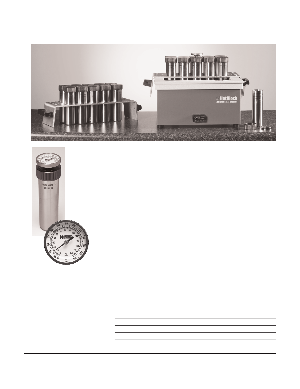
The Soil Extraction
Reference Cell is used
to monitor the internal
temperature of the
solvent during the
extraction process. This
cell can be used for
a sample extraction
and should follow
the same procedure
as the regular K8000
Soil Extraction Cell.
One reference cell
is provided
with each
complete
system.
Soil Extraction Cell Specications:
• Stainless Steel Body
• Aluminum Threaded Outer Cap
• Stainless Steel Inner Lid
with Rupture Seal
• Viton® O-ring
Soil Extraction Cells are designed to work with our 100mL HotBlocks.
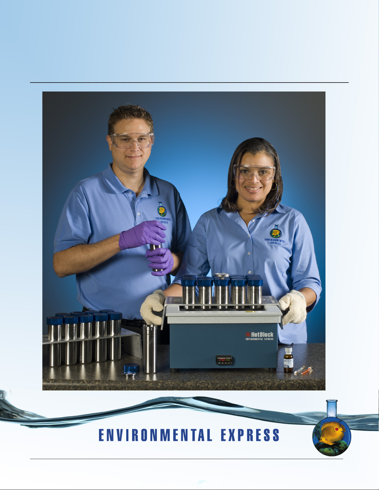
Environmental Express, known for its innovative products, has developed the
Soil-CellTM System for the extraction of semi-volatile organic compounds in soil
samples. The Soil-CellTM System meets the requirements of the Performance Based
Measurement System established by the EPA and replaces microwave technology
with a HotBlockTM and stainless steel Soil Extraction Cells. Analytical results of a
CRM (Certied Reference Material) for PAH/BNA and TPH fell within the required
acceptance limits and were very reproducible. Real world soil samples were also
extracted using this procedure for PAH/BNA and PCB compounds and compared
to results achieved using SW846 Method 3545A. Results were comparable for both
groups of compounds.
The K8150 Soil-CellTM System features a 25-well HotBlockTM and accommodates 25
Soil Extraction Cells while the K8151 features a 35-well block and holds 35 cells.
Each system comes with the appropriate number of Soil Extraction Cells, one
Temperature Reference Cell and aluminum racks for easy handling.
Description Catalog #
Soil-Cell System, 25-Sample Capacity HotBlock and Racks K8150
Soil-Cell System, 35-Sample Capacity HotBlock and Racks K8151
Individual Soil Extraction Cell Complete, Each K8000
Temperature Reference Cell Complete, Each K8000R
Replacement parts, see page 2.
HotBlock Specications: K8150 K8151
Footprint: 15" x 15" 15" x 21.5"
Crated Size: 23" x 23" x 17" 26" x 23" x 17"
Weight: 42 lb. 59 lb.
Shipping Weight: 54 lb. 65 lb.
Electrical: 120VAC, 9A 120VAC, 13A
Sample Capacity: 25 35
Temperature Range: to 150ºC to 150ºC
Thermocouple: Type K Type K
800.745.8218 / 843.576.1147 / www.environmentalexpress.com Environmental Express • 1
Page 4
Soil-Cell: Operation and Instruction Manual General Information
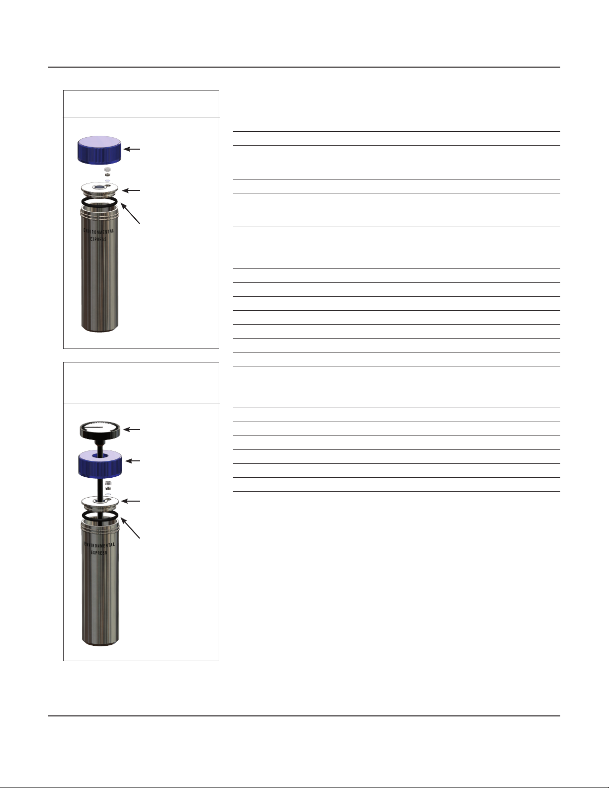
Soil Extraction Cell, K8000
K8003
Threaded Outer Cap
K8002
Stainless Steel
Inner Lid
K8004
Viton® O-ring
Temperature
Reference Cell, K8000R
K8006
Thermometer for
Reference Cell
K8003R
Threaded Outer Cap
K8002R
Stainless Steel
Inner Lid
K8004
Viton® O-ring
Soil-Cell System Replacement Parts
Soil-Cell Systems
Description Catalog #
Soil-Cell System with 25-well HotBlockTM
Comes with 24 Soil Extraction Cells, one Reference Cell and one
10-place Aluminum Rack and one 15-place Aluminum Rack. K8150
Rack Set for K8150 K8008-25
Soil-Cell System with 35-well HotBlockTM
Comes with 34 Soil Extraction Cells, one Reference Cell and two
10-place Aluminum Racks and one 15-place Aluminum Rack. K8151
Rack Set for K8151 K8008-35
Soil Extraction Cell Parts
Description Quantity Catalog #
Soil Extraction Cell Complete Each K8000
Threaded Outer Cap Each K8003
Stainless Steel Inner Lid Each K8002
Viton® O-ring 25/pk K8004
Aluminum Foil Rupture Seal 100/pk K8007
25-Well HotBlockTM - SC150
35-Well HotBlockTM - SC151
Temperature Reference Cell Parts
Description Quantity Catalog #
Thermometer for Reference Cell Each K8006
Threaded Outer Cap for Reference Cell Each K8003R
Stainless Steel Inner Lid for Reference Cell Each K8002R
Viton® O-ring for Reference Cell 25/pk K8004
Aluminum Foil Rupture Seal 100/pk K8007
Individual Temperature Reference Cell Complete Each K8000R
800.745.8218 / 843.576.1147 / www.environmentalexpress.com Environmental Express • 2
Page 5

Soil-Cell: Operation and Instruction Manual Adaptation of EPA Method 3546
Adaptation of EPA SW846 Method 3546 for use with the Environmental Express HotBlock
1.0 Scope and Application
1.1 The following procedures have been written as an aid to EPA SW846
Method 3546 for use with the Environmental Express HotBlockTM. EPA
SW846 Method 3546 is a procedure for extracting water insoluble or
slightly water soluble organic compounds from soils, clays, sediments,
sludges, and other solid wastes. Prior to using this method, users are
advised to consult the determinative method for additional information
on quality control procedures, development of QC acceptance criteria,
calculations, and general guidance.
2.0 Apparatus and Materials
2.1 HotBlockTM for Sample Extraction – Model Numbers SC150 or SC151
2.2 Soil Extraction Cell, Complete Unit – Catalog# K8000
2.3 Soil Extraction Temperature Reference Cell Complete – Catalog# K8000R
2.4 Drying Agent such as Diatomaceous Earth or Sodium Sulfate
2.5 Extraction Solvents
2.6 Buchner Funnel
2.7 Filter Paper (Glass Fiber)
2.8 Surrogates
2.9 Standards
2.10 Vials
TM
3.0 HotBlockTM Procedure for Method 3546:
3.1 When practical, air dry the sample at room temperature for 48 hours
in a glass tray or on hexane-rinsed aluminum foil. Alternatively, mix
the sample with an equal volume of anhydrous sodium sulfate or
diatomaceous earth until a free-owing powder is obtained. A percent
dry weight should be performed on a separate aliquot of sample for the
percent dry weight calculation at the end of the analysis.
3.2 Weigh 10 – 30g of sample into the Soil Extraction Cell. Amount may vary
depending on individual laboratory needs.
3.3 Add approximately 30 mLs of solvent. (This method was validated using
Methylene Chloride. Other solvents may be used but must be validated
by the individual laboratory).
3.4 Add the surrogates and/or spikes listed in the determinative method to
each appropriate sample.
3.5 Place the stainless steel inner lid with Viton® O-ring in the Soil Extraction
Cell.
3.6 Hand-tighten the threaded outer cap onto the Soil Extraction Cell.
3.7 Heat the HotBlock to 130º C. This will yield an internal solvent
temperature of 100 – 115º C which is recommended by Method 3546.
800.745.8218 / 843.576.1147 / www.environmentalexpress.com Environmental Express • 3
Page 6

Soil-Cell: Operation and Instruction Manual Adaptation of EPA Method 3546
3.8 Put the Soil Extraction Cells into the HotBlock and heat for 30 minutes
at a block temperature of 130º C. This will give samples 10 – 20 minutes
at the appropriate temperature for extraction which is recommended by
Method 3546.
3.9 Remove the cells and allow them to cool to room temperature.
3.10 Unscrew the threaded outer cap and remove. Take care in doing this step
as pressure will develop in the Soil Extraction Cells during the heating
process.
3.11 Take out the stainless steel inner lid and rinse with the appropriate
solvent, taking care to collect this rinsate in the cell.
3.12 Proceed with ltering and rinsing, collecting all ltrates. A Buchner
funnel with vacuum is recommended but any appropriate laboratory
ltration device may be used.
3.13 The extract is now ready for concentration, cleanup, and analysis.
All QC samples, limitations, interferences, and reagent specications are addressed
in depth in EPA Method 3546. Safety concerns are also part of the full method.
Follow the instructions listed in EPA Method 3546. These steps should only be used
as a guide.
Recommended Surrogates and Other Consumables
Description Catalog #
Base-Neutral, 100 ug/mL; Acid, 100 ug/mL, 25mL M0011
Base-Neutral, 100 ug/mL; Acid, 100 ug/mL with CLP, 25mL M0013
Nonatriacontane, 80 ug/mL; O-Terphenyl, 80 ug/mL, 25mL M0030
Pesticide/PCB Surrogate Solution, 200µg/mL, 1mL GCS130023-07
Herbicide Surrogate Solution, 2000µg/mL, 1mL GCS011025-01
Pelletized 60 Mesh Diatomaceous Earth, 4kg K6180-4
Sodium Sulfate, Anhydrous, 500g LC248801
800.745.8218 / 843.576.1147 / www.environmentalexpress.com Environmental Express • 4
Page 7

Soil-Cell: Operation and Instruction Manual About Your HotBlock
Limited Warranty
The Environmental Express HotBlockTM is warranted against defects in materials and workmanship when used in
accordance with applicable instructions, for a period of one year from the date of shipment. This warranty extends to parts,
labor, and any approved transportation charges. This warranty applies only to damage or failure caused by normal laboratory
use. The warranty is limited to product repair. If Environmental Express is unable to repair the HotBlockTM, the customer may,
at his or her option, receive a replacement unit or a full refund. Operating the HotBlockTM at temperatures higher than 150°C
will void the warranty.
Environmental Express makes no other warranty, expressed or implied for this product with respect to merchantability,
tness for a particular use or any other matter. Environmental Express is not liable for any consequential or compensatory
damages arising from use of, or in conjunction with this product. The maximum liability shall be the invoice price of this
product.
Repair Policies
Under Warranty Repair:
If the HotBlockTM should fail to operate within the warranty period (one year from date of shipment) Environmental
Express will repair it and ship it back to the customer at our expense. The remainder of the warranty period will be
honored from the original ship date. Environmental Express will bear the cost of ground transportation both to and from
the customer’s location, and bear the cost of any parts, labor and cleanup required. However, if it is determined that
the damage to the HotBlockTM was caused by negligence or improper use, this warranty will not apply. The warranty is
also void if the system is used beyond its intended purpose or in the event of any unauthorized repair. In such cases,
reasonable and customary repair charges will apply. Repair charges will be quoted prior to work being done.
TM
Out of Warranty Repair:
If the HotBlockTM fails after the warranty period has lapsed, the repair procedure is as follows: First, notify an
Environmental Express Technical Service Representative of product’s failure and place an order for repair. Whenever
possible, our customer service technician will walk you through possible troubleshooting scenarios which may enable you
to repair your block on site. (See the troubleshooting section of this manual, pages 11-13).
If on site repair is not possible, the customer may return the non-working unit to Environmental Express using
appropriate shipping containers and insurance. Repair charges will be assessed and estimated prior to work being done.
Repair charges will include all freight costs as well as reasonable and customary charges for parts and labor.
Loaner HotBlocksTM MAY be available during the repair period. There are only a limited number of these units.
A reasonable charge for “cleanup” will be charged if a loaner is issued. The customer will be responsible for all
shipping charges associated with a loaner unit.
843.881.6560 • www.environmentalexpress.com
2345 A Charleston Regional Pkwy • Charleston, SC 29492
Product Information:
Item # Date of Purchase
HotBlockTM Serial #
Please record the serial # of your HotBlockTM here for easy reference. Your serial # is located on the back of your HotBlockTM.
800.745.8218 / 843.576.1147 / www.environmentalexpress.com Environmental Express • 5
Page 8

Soil-Cell: Operation and Instruction Manual HotBlockTM Declaration of Conformity
The manufacturer, Environmental Express, 2345A Charleston Regional Parkway,
Charleston, SC 29492 declares that the following products:
HotBlockTM Catalog Numbers- SC196, SC154, SC150, SC151, SC100, and C6002 are in conformity with:
Standard for Safety Electrical Equipment for Measurement, Control, and Laboratory Use; Part 1 General Requirements, UL
61010-1, CAN/CSA-C22.2 No. 61010-1, 2nd Edition, Issued 12 July, 2004 with revisions through and including 28 October,
2008; Equipment for Measurement, Control, and Laboratory Use Part 2-010: Particular Requirements for Laboratory
Equipment for the Heating of Materials, IEY 61010-2-010, 2nd Edition, Issued 1 June, 2003, Safety Requirements for
Electrical Equipment for Measurement, Control, and Laboratory Use - Part 2-010:Particular Requirements for Laboratory
Equipment for the Heating of Materials, CSA C22.2.61010.2.01
Signed: ________________________________________
Al Jurgela, Chief Executive Ofcer
4000040
800.745.8218 / 843.576.1147 / www.environmentalexpress.com Environmental Express • 6
Page 9

Soil-Cell: Operation and Instruction Manual About Your HotBlock
Information and Markings
Environmental Express HotBlocksTM provide an efcient method of digesting and storing water, wastewater, soil and sludge
samples for metals analysis. These innovative digestion systems allow samples to be digested in a corrosion-free environment.
In addition, samples are handled in a small area with minimal radiant heat loss. Users should be aware of potential dangers
from heating certain types of compounds. Such hazards may include explosion or the release of toxic or ammable gases.
Each HotBlock displays certain markings and symbols. All personnel working with the HotBlocks should have an
understanding of the following symbols and denitions:
• V = voltage
• ~ = alternating current
• Hz = frequency
• A = amperes
This symbol means Caution
Hot Surface. The surface of the
HotBlock may be too hot to
safely touch with bare hands.
This symbol means Read
and become familiar with
instructions before operation of
instrument.
Unpacking Your HotBlockTM:
TM
1. Remove the HotBlockTM from the shipping container by lifting from the bottom of the block. The lid should not be
used for lifting.
2. Your HotBlockTM is shipped with metal screws securing the bottom panel. The metal screws must be removed before
operating your HotBlockTM. Remove the metal screws and replace them with the PVC screws and rubber feet included
with your shipment. The corrosion-resistant PVC screws and rubber feet are designed to secure the bottom plate.
Important: Do not over tighten the PVC screws!
Installation Requirements
Locate the HotBlockTM under a fume hood with a minimum face velocity of 100fpm, and allow a minimum of 2" of space
on all sides. The following environmental conditions should be observed:
• Ambient temperature range: 5-30°C
• Ambient relative humidity: 0-90%RH
• Altitude: sea level to 2500 meters
HotBlocksTM are rated as Pollution Degree 2 and Installation Category 2.
Electrical Requirements
Required Voltage: 120 volts, ~60Hz, 15A (all HotBlocksTM are also available in 240V with CE mark)
Power should not vary greater than±10%. Use the supplied heat-resistant power cord or equivalent to connect to the
power supply.
For safety reasons, a separate power receptacle should be provided for each unit in the system. Do not use extension
cords or outlet adaptors. Make certain that power outlets are earth-grounded at the grounding pin.
See individual specications for each HotBlock model.
800.745.8218 / 843.576.1147 / www.environmentalexpress.com Environmental Express • 7
Page 10

Soil-Cell: Operation and Instruction Manual About Your HotBlock
HotBlockTM Temperature Settings:
The pre-set factory “set point” temperature of your HotBlockTM is 106°C. Factory tests have shown that this temperature is
“sea level safe.” Liquids in uncovered polypropylene tubes should not boil at this setting. Please note that the set point of the
block is not the same as the temperature of the liquids being digested. The block temperature should be optimized for the
specic digestion. The temperature of liquid contents of the digestion cup will vary according to:
• The material being digested
• The number of samples being digested
• The air movement of the digestion area
• The addition of a watch glass or reux cap
If watch glasses are being used, the control point temperature should be
lowered approximately 10°C to avoid boiling.
Note: The maximum sample temperature tolerance for our polypropylene digestion vessels (SC475) is 130°C.
Remember that the temperature display (current block temperature) is not the temperature of the sample. Sample temperature
will usually be 5-15° less than the display temperature.
Adjusting the Temperature of Your HotBlock:
TM
1. Plug the HotBlockTM into an approved receptacle. Turn the HotBlock on by pressing the button on the back of the unit.
Wait until the display shows the current block temperature (in red) and the set point temperature (in green).
2. Press and hold or tap the or key. The display will show the set point temperature on the right in blue. The
adjustment is from ambient to 150°C in increments of 0.1°C. There is no need to press the green (advance) or ∞ button.
Safe-Sample™ Temperature Protection:
Your HotBlockTM is protected from runaway temperatures by a fail-safe alarm system. In the unlikely event that the
heating system fails to respond to the controller, the Safe-Sample™ system will automatically shut the system off and sound an
audible alarm.
This alarm sequence occurs if the actual temperature of the block reaches a temperature that is fteen degrees higher
than the set point temperature. If this should occur, the HotBlockTM will stop heating, preventing the loss of samples. The
HotBlock must be turned off, then turned back on to reset the alarm.
If the alarm sounds, see the troubleshooting section of this manual, pages 13-15.
800.745.8218 / 843.576.1147 / www.environmentalexpress.com Environmental Express • 8
Page 11

Soil-Cell: Operation and Instruction Manual About Your HotBlock
Potential Hazards:
The HotBlockTM should only be operated by properly trained personnel using standard laboratory safety practices.
Use extreme caution when operating the HotBlockTM. Plastic and graphite surfaces of the HotBlockTM may be too hot to
safely touch with bare hands.
The HotBlockTM contains electrical circuits and devices and compounds operating at dangerous voltages. Contact with
these circuits, devices and components can cause serious injury or painful electric shock.
Proper grounding is essential to avoid a potentially serious electric shock hazard. Ensure that there is an internal ground
connection between the metal base of the system and the 3-pin, earth-grounded receptacle.
For safety reasons a separate power outlet receptacle should be provided for each unit in the system. Do not use
extension cords or outlet adaptors. Make certain each power outlet is earth-grounded at the grounding pin.
See individual block specications for power requirements.
Application of the wrong supply voltage can create a re hazard and a potentially serious shock hazard, and could
seriously damage the HotBlockTM system. See specications for individual HotBlocks.
Users should be aware of potential dangers from heating certain types of compounds. Such dangers may include
explosion or the release of toxic or ammable gases.
Always lift the HotBlockTM from the bottom of the unit.
TM
Maintenance:
Any service inquiries should be directed to Environmental Express Technical Service Department.
After each use, clean exterior surfaces with a damp sponge to remove acid residue.
For acid spills, sponge with a diluted solution of sodium bicarbonate followed by distilled water. Acid that is spilled
directly into the digestion wells should be neutralized and removed.
Before using any cleaning or decontamination methods except those recommended, check with Environmental Express
to conrm the proposed method will not damage your HotBlockTM.
Avoid excessive spills, as liquid allowed to overow into the HotBlockTM casing can severely damage electronic
components.
HotBlockTM Replacement Parts
Description Catalog #
Power module (plug receptacle) w/ push button switch SC941
Power Cord- heavy duty SC958
Environmental Express Controller SC945
12" X 12", 120V, silicone rubber,
etched-foil heater mat for model SC150 SC951
12" X 12", 240V, silicone rubber,
etched-foil heater mat for model SC150-240 SC951-240*
110/220V, 25A solid state relay SC952
Type K Thermocouple SC953
Terminal board SC955
Ceramic ber insulation for model SC150 SC959
14" X 14" Powder-coated aluminum bottom
for model SC150 SC963
Description Catalog #
12" X 18", 120V, silicone rubber,
heater mat for model SC151 SC966
12" X 18", 240V, silicone rubber, heater mat
for model SC151-240 SC966-240*
Fail-Safe Relay SC968
Alarm Buzzer SC969
Ceramic ber insulation for models SC151 SC970
14" X 19", powder-coated aluminum bottom
for model SC151 SC971
PVC screw for rubber foot SC964
Rubber foot SC976
*for HotBlocks shipped outside the United States and Canada
800.745.8218 / 843.576.1147 / www.environmentalexpress.com Environmental Express • 9
Page 12

Soil-Cell: Operation and Instruction Manual Circuitry Diagram
800.745.8218 / 843.576.1147 / www.environmentalexpress.com Environmental Express • 10
Page 13

Soil-Cell: Operation and Instruction Manual Troubleshooting Your HotBlock
HotBlockTM Troubleshooting Guide:
Please consult the following troubleshooting guide if you experience problems with your HotBlockTM. See wiring
schematic
(page 10) for component identication. If you are unable to resolve the problem or if replacement components are necessary,
please contact technical service at 1-800-745-8218 as component replacement varies in degree of difculty. We recommend
that only qualied personnel attempt troubleshooting electrical components.
When the HotBlockTM is initially powered on, the controller will cycle through a self-test sequence. It will then display the
current temperature and begin heating until it reaches your set point temperature, where it will hold until the unit is powered
off. The set point may be changed at any time. A change in the controller’s factory default settings or a failed component may
cause the HotBlock to perform unsatisfactorily or render it inoperable.
TM
The controller digital display will
not illuminate.
There are two possible reasons that your controller will not illuminate.
1. The controller is not getting voltage or;
2. The controller itself has failed internally.
The problem can be effectively diagnosed by determining if the controller is or
is not getting voltage using the following steps:
1. Conrm that the power cord is plugged securely into the HotBlockTM
receptacle and a working outlet.
2. Conrm that the switch is in the “on” position. Press button on the back of
HotBlockTM.
3. Check the fuse located in the power module:
a. Locate the fuse drawing indented into the power module next to the
socket.
b. Using a small screwdriver, pry open the fuse compartment cover.
c. Examine the exposed fuse for a break in the lament and if necessary,
check for continuity using a volt-meter.
d. If the fuse is determined to be blown, replace it with the spare fuse
located in the slide-out compartment beneath the operating fuse.
Caution: This procedure is a potential electrical hazard and should
only be performed by qualied personnel.
4. Inside the HotBlockTM, check voltage leading from the power module to
the controller:
a. Remove the bottom panel of the HotBlockTM by unscrewing the rubber
feet.
b. On the back of the controller, locate the black wire at terminal 98 and
white wire at terminal 99.
c. Set your volt-meter on AC voltage.
d. Touch your red lead to the exposed white wire and black lead to the
exposed black wire.
e. If your volt-meter reads 110-122V, the controller is receiving power but
has failed internally. It must be replaced.
f. If your volt-meter registers less than 110-122V, using step d above check
the black and white wires at the terminal board and then at the power
module to determine if there is a faulty connection.
800.745.8218 / 843.576.1147 / www.environmentalexpress.com Environmental Express • 11
Page 14

Soil-Cell: Operation and Instruction Manual Troubleshooting Your HotBlock
TM
The audible alarm has sounded
immediately after powering on
and the HotBlockTM will not heat.
The temperature has overshot
the set point and the audible
alarm has sounded.
There are two possible causes for your HotBlockTM to sound the alarm
immediately after the controller cycles through the self test. These are:
1. Your set point has been set to a value (≥) 15° less than ambient or current
set point temperature. Turn the set point to within 15° of the actual
temperature (blue numbers)
2. The controller is faulty. Call Environmental Express at 1-800-745-8218 for
more information.
The function of the fail-safe system is to cease heating of the HotBlockTM in the
event of a set point overshoot of 15°C and to alert the technician of the incident.
The HotBlockTM can be “fooled” into fail-safe mode if the set point is manually
changed to a value ≥15° below your current temperature. However, the primary
cause for the runaway temperature is a faulty relay that has exceeded its
useful life.
You may troubleshoot the relay by following these steps:
Caution: This procedure is a potential electrical hazard and should only
be performed by qualied personnel.
1. Power off your HotBlockTM.
2. Remove the bottom panel of the HotBlockTM by unscrewing the rubber feet.
3. Power the HotBlockTM on and allow it to overshoot your set point
temperature.
4. Locate the solid state relay mounted to the bottom panel.
5. Set your volt-meter to measure AC voltage.
6. Touch your red lead to terminal T1 (white wire) of the solid state relay and
touch your black lead to a ground source (e.g., the green/yellow wire from
the power module or an empty terminal on the terminal board).
7. If your volt-meter reads 110V-122V, then the relay is stuck in the “closed”
position and it must be replaced. (see parts list, page 11).
The temperature controller is
performing erratically or displays
an error message.
-OR-
The temperature controller is
ashing Er.L Attn- Thermocouple
First reset default settings
1. Hold the up and down arrow buttons for six seconds until Ai Set appears
2. Hold the down arrow until glbl set is in the window
3. Press the green advance key to enter
4. Continue pressing the green advance key until none user appears.
5. Press the down arrow key until Set1 user appears.
6. Pressing the advance key will restore default settings.
Fault
To troubleshoot the thermocouple, follow these steps:
1. Power off your HotBlockTM.
2. Remove the bottom panel of your HotBlockTM by unscrewing the rubber feet.
3. Locate the thermocouple wires at terminals R1 (yellow) and S1 (red) of the
controller and remove using a small screwdriver.
4. Cut the exposed ends of the two wires.
5. Strip 1/4" of insulation from each wire and reconnect them to the
appropriate controller terminal and tighten.
6. Power on your HotBlockTM.
7. If your display continues to ash Er.1 Attn- the thermocouple is faulty and
must be replaced. (see parts list, page 11).
800.745.8218 / 843.576.1147 / www.environmentalexpress.com Environmental Express • 12
Page 15

Soil-Cell: Operation and Instruction Manual Troubleshooting Your HotBlock
TM
The HotBlockTM will not heat
beyond ambient temperature.
A HotBlockTM that will not heat beyond ambient temperature typically has a failed
relay, heater mat or controller.
Relay: To test the relay, the output voltage must be determined with a volt-meter.
Caution: This procedure is a potential electrical hazard and should only
be performed by qualied personnel.
To measure the relay voltage, follow these steps:
1. Remove the bottom panel of your HotBlockTM by unscrewing the rubber feet.
2. Locate the solid state relay mounted to the bottom panel.
3. Set your volt-meter to measure AC voltage.
4. Touch your red lead to terminal T1(white wire) of the solid state relay and
touch your black lead to a ground source (i.e., the green/yellow wire from the
power module or an empty terminal on the terminal board).
5. If your volt-meter does not read 110V-122V, then the relay has stuck in the
open position and it must be replaced (see parts list, page 11).
Heater Mat: To test the heater mat, the resistance in ohms (Ω) must be determined
with a volt-meter. It is recommended that your heater mat be replaced if it
measures 25 ohms (Ω) or greater. It is also recommended that the thermocouple
and insulation be replaced as well, both are inexpensive parts that are not easily
accessible otherwise.
To measure your heater mat resistance, follow these steps:
1. Power off your HotBlockTM and remove the bottom panel of your HotBlockTM by
unscrewing the rubber feet.
2. Locate and disconnect the white wire connected to terminal T1 of the relay
and an identical wire on terminal #2 of the terminal board (note: terminal #2
of the terminal board contains 3 white wires. To ensure you have the correct
wire, trace it back and ensure it originates from the graphite portion of your
HotBlockTM.
3. Set your volt-meter to measure ohms (Ω)
4. Touch the red lead to one of these wires and touch the black lead to the
remaining wire.
5. If your reading is “OL” (over limit) or a value greater than 25 ohms, then the
heater mat has failed and it must be replaced (see parts list, page 11).
Controller: To test the controller, the output voltage must be determined with a
volt-meter.
Caution: This procedure is a potential electrical hazard and should only
be performed by qualied personnel.
To measure voltage from the controller, follow these steps:
1. Remove the bottom panel of your HotBlock by unscrewing the rubber feet.
2. Locate the solid state relay mounted to the bottom panel.
3. Set your volt-meter to measure DC voltage.
4. Touch the red lead to terminal A1 (red) and the black lead to terminal A2 (blue)
of the solid state relay.
5. Your volt-meter should read 3V-16V.
6. If your volt-meter does not read 3V-16V, perform steps 3 and 4 on the red and
blue (5 and 6) wires at the terminal board and controller to determine if there
is a faulty or loose connection.
7. If you do not get a reading of 3V-16V at terminals Y2 (red) and W2 (blue) of the
controller then the controller has failed internally and it must be replaced (see
replacement parts list, page 9).
800.745.8218 / 843.576.1147 / www.environmentalexpress.com Environmental Express • 13
 Loading...