

Page 1
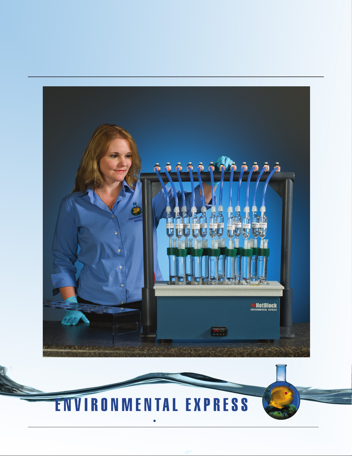
SimpleDist™ System
Call 800.343.5319 or 843.881.6560 www.environmentalexpress.com
Call 800.343.5319 or 843.881.6560 www.environmentalexpress.com
Call 800.343.5319 or 843.881.6560 www.environmentalexpress.com
Operation & Instruction Manual
Copyright, Environmental Express, Inc, September 2013
Page 2
SimpleDist: Operation and Instruction Manual Contents
Dear Valued Customer,
Thank you for purchasing a
SimpleDistTM System from
Environmental Express.
We pride ourselves on
providing innovative
products designed
to improve accuracy,
efciency, and safety
in your laboratory. Please take some
time to read your product manual
before using your SimpleDistTM.
As always, our Technical Sales
and Technical Support Teams are
available to assist with any questions
you have regarding our products.
Best Regards,
Al Jurgela
Chief Executive Ofcer
Environmental Express, Inc.
Contents
General Information
Limited Warranty and Repair Policies 1
Parts and Supplies 2-3
Safety Information 4
Getting Started
Setup and Assembly 5
About Your HotBlock
TM
HotBlockTM Declaration of Conformity 6
HotBlockTM Information and Markings 7
HotBlockTM Unpacking and Installation 8
HotBlockTM Temperature Information 9
HotBlockTM Potential Hazards and Maintenance 10
Diagrams
Tubing Valve Assembly, Figure 1 11
Boiling Tube Assembly, Figure 2 12
Assembly Complete System, Figure 3 13
System Operation
Total Cyanide Distillation 14-15
Ammonia Distillation 15-16
Care and Maintenance of Your SimpleDist
TM
Circuitry Diagram 17
Troubleshooting SimpleDistTM 20
Troubleshooting Your BlockTM 21-21
HotBlock
TM
Replacement Parts 22
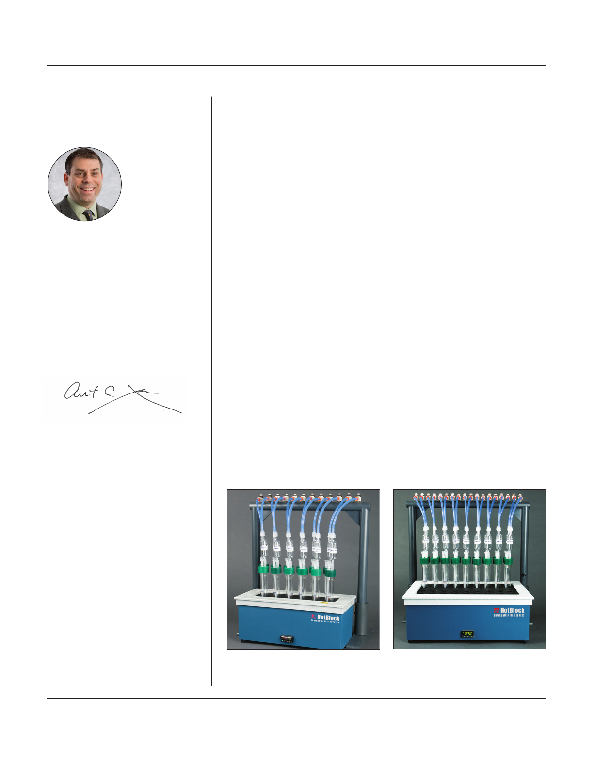
The C6000 SimpleDistTM Complete System is
shown here. The 12-place Manifold Kit is also
sold separately, C6210, and ts the 36-well SC100
HotBlockTM or the 12-place HotBlockTM, C6002.
800.745.8218 / 843.576.1147 / www.environmentalexpress.com Environmental Express
Pictured above, the 18-place SimpleDistTM Manifold
Kit, C6200, ts the SC154 HotBlockTM.
Page 3
SimpleDist: Operation and Instruction Manual General Information
Limited Warranty
The SimpleDistTM System from Environmental Express, Inc. is guaranteed to heat, hold temperature, and adequately perform
specied laboratory distillations for a period of one year from the date of shipment. This warranty extends to parts, labor, and
any approved transportation charges. This warranty applies only to damage or failure caused by normal laboratory use.
Environmental Express, Inc. makes no other warranty, expressed or implied for this product with respect to merchantability,
tness for a particular use or any other matter. Environmental Express, Inc. is not liable for any consequential or compensatory
damages arising from use of, or in conjunction with, this product. The maximum liability shall be the invoice price of this
product.
Repair Policies
Under Warranty Repair:
If the SimpleDistTM should fail to operate within the warranty period (one year from date of shipment) Environmental
Express, Inc. will repair it and ship it back to the customer at our expense. The remainder of the warranty period will be
honored from the original ship date. Environmental Express, Inc. will bear the cost of ground transportation both to and
from the customer’s location, and bear the cost of any parts, labor and cleanup required.
However, if it is determined that the damage to the SimpleDistTM System was caused by negligence or improper use, this
warranty will not apply. The warranty is also void if the system is used beyond its intended purpose or in the event of any
unauthorized repair. In such cases, reasonable and customary repair charges will apply. Repair charges will be quoted prior
to work being done.
Out of Warranty Repair:
If the SimpleDistTM System fails after the warranty period has lapsed, the repair procedure is as follows:
First, notify an Environmental Express, Inc. customer service representative of product’s failure and place an order for
repair. Whenever possible, our customer service technician will walk you through possible troubleshooting scenarios which
may enable you to repair your block on site.
If on-site repair is not possible, the customer may return the non-working unit to Environmental Express, Inc. using
appropriate shipping containers and insurance. Repair charges will be assessed and estimated prior to work being done.
Repair charges will include all freight costs as well as reasonable and customary charges for parts and labor.
Note: This warranty does not apply to any glassware associated with the SimpleDistTM System.
2345 A Charleston Regional Pkwy • Charleston, SC 29492
Product Information:
Item # Date of Purchase
HotBlockTM Serial # (if applicable)
If you ordered the C6000 please record the serial # of your HotBlockTM here for easy reference. Your serial # is located on the back of your HotBlock
TM
.
800.745.8218 / 843.576.1147 / www.environmentalexpress.com Environmental Express • 1
Page 4

SimpleDist: Operation and Instruction Manual General Information
Parts and Supplies
SimpleDistTM Complete System C6000
Parts and Supplies Included:
Description Catalog #
12-well HotBlockTM C6002
12-valve Manifold Kit C6210
SimpleDistTM Manual
Includes operating Instructions with wiring diagram and temperature controller operating instructions.
12-well HotBlock
Parts and Supplies Included:
The 12-place HotBlockTM is a compact block for laboratories digesting small batches of 50mL samples. Each block comes with a
specially designed 12-place polycarbonate tube rack (C6050) and has the same sturdy construction and features of our other HotBlockTM
Systems.
Description Catalog #
Tube Rack
For handling 12 boiling tubes simultaneously, polycarbonate C6050
Power Cord SC958
TM
C6002
12-valve Manifold Kit C6210
Parts and Supplies Included:
Description Catalog #
12-valve PVC Vacuum Manifold C6003B
Base Supports, 2 piece set C6007B
12 Flow Control Valves
Push lock design, accepts 3/8" diameter tubing C6005 each
1 PVC Hose Barb for SCS, 1/4" C6160
12 Boiling Tubes
30mm x 200mm threaded boiling tubes marked at 50mL, borosilicate glass C6010 each
1 pack Collection Traps
Disposable polystyrene C6100 100pk
1 pack Polypropylene Reagent Addition Tubes C6110 100pk
2 packs Caps
38mm open top closures C6120 6pk
2 packs Black Neoprene Washers C6120A 6pk
2 packs 2-Port Cap Inserts C6130 6pk
1 12-Piece Tubing Kit
Tubing kits come with 12 lengths of tubing (3/8" OD X 1/4" ID). Six pieces of tubing are 8" and the other 6 are 10.25". The longer pieces
extend from the manifold valves to the front row of sample collection asks while the shorter lengths go to the back row of collection asks.
Each length of tubing comes with a tubing adaptor and a barbed tting adaptor already inserted. C6142
Tubing Adaptors C6140 12pk
Barbed Tubing Adaptor C6006 6pk
800.745.8218 / 843.576.1147 / www.environmentalexpress.com Environmental Express • 2
Page 5

SimpleDist: Operation and Instruction Manual General Information
18-valve Manifold Kit C6200
Parts and Supplies Included:
Description Catalog #
18-valve PVC Vacuum Manifold C6007A
Base Supports, 2 pieces C6007B
18 Flow Control Valves C6005 each
Push lock design, accepts 3/8" diameter tubing
1 PVC Hose Barb for SCS, 1/4" C6160
18 Boiling Tubes C6010 each
30 mm. x 200 mm. threaded boiling tubes marked at 50mL, borosilicate glass
1 pack Collection Traps C6100 100pk
Disposable polystyrene
1 pack Polypropylene Reagent Addition Tubes C6110 100pk
3 packs Caps C6120 6pk
38 mm. open top closures
3 packs Black Neoprene Washers C6120A 6pk
3 packs 2-Port Cap Inserts C6130 6pk
2 12-Piece Tubing Kits C6142
Tubing kits come with 12 lengths of tubing (3/8" OD X 1/4" ID). Six pieces of tubing are 8" and the other 6 are 10.25". The longer pieces
extend from the manifold valves to the front row of sample collection asks while the shorter lengths go to the back row of collection f
lasks. Each length of tubing comes with a tubing adaptor and a barbed tting adaptor already inserted.
Tubing Adaptors C6140
Barbed Tubing Adaptors C6006 6pk
Snip & Pour, 0.2N H2SO4 C7005 50x5mL
Snip & Pour, 1.25N NaOH C71155 50x5mL
Snip & Pour, 20g/L Boric Acid C7125 50x5mL
SimpleDist Manual
Includes operating Instructions with wiring diagram and temperature controller operating instructions.
800.745.8218 / 843.576.1147 / www.environmentalexpress.com Environmental Express • 3
Page 6

SimpleDist: Operation and Instruction Manual General Information
Safety Information
1. The Environmental Express SimpleDistTM System should be set up and operated in a chemical fume hood with a face
velocity of not less than 100 CFM.
2. Wear appropriate Personal Protective Equipment (PPE) suitable for use with caustic and corrosive materials.
3. Do not operate the SimpleDistTM System in the vicinity of combustible material.
4. Consult your in-house electrician to be certain the SimpleDist System power cord is properly grounded.
5. During operation the surfaces around the heater assembly will get HOT. Do not touch the outer surface.
6. Do not move the SimpleDistTM System while hot.
7. Do not attempt to operate the SimpleDistTM System block over 180°C.
8. Review Material Safety Data Sheets for all materials used or generated during the operation of the SimpleDistTM
System.
Avoid breathing any vapors that may come off of the SimpleDistTM System; they may be harmful or fatal.
9. Vacuum should be continued until the SimpleDistTM System has cooled down and the collection trap is removed
from the assembly.
10. The power should be kept plugged into its outlet until the unit has cooled down.
11. If boil over does occur during operation of the SimpleDistTM System operation, immediately wipe the system down
with neutralizing solution, such as a mild solution of sodium bicarbonate.
12. Unplug the SimpleDistTM System from the outlet prior to cleaning exterior surfaces. Wipe with damp sponge or
towel after each use, rst with mild sodium bicarbonate or similar solution followed by DI or distilled water. Avoid
solutions on or near the controls.
13. Install an excess gas trap in the vacuum line to remove excess vapors.
14. Use of micro-porous boiling chips in each distillation ask may help to prevent bumping.
Note: The above list contains some basic recommendations and safety precautions. By no measure should this list be considered
complete. More rigorous enhanced precautions may be necessary while operating this equipment. Please consult your Safety
Manager and Material Safety Data Sheets prior to operating this equipment.
Contact Environmental Express Inc. if there are any questions. User assumes all liability for damages arising from the operation
of this equipment.
800.745.8218 / 843.576.1147 / www.environmentalexpress.com Environmental Express • 4
Page 7

SimpleDist: Operation and Instruction Manual Getting Started
Setup and Assembly:
1. Unpack the heating unit and place it in a chemical fume hood with the temperature controller facing outward. (If
you are purchasing a manifold kit to use with a previously purchased HotBlockTM, skip to step 2).
2. Unpack boiling asks. The boiling asks should be cleaned according to laboratory protocol and assembled in the
SimpleDistTM block.
3. Unpack the bags of tubing which were packed with the heating unit.
4. Review the diagrams and familiarize yourself with parts, names, and locations of the parts for the chemistry you are
doing.
5. Save original packaging material in a dry area for use if unit needs to be returned for service. Refer to warranty
policy on page 1.
6. Assemble the vacuum manifold and base supports and then tighten 4" set screws using an 3/16" Allen
wrench.
7. Place vacuum manifold containing ow control valves behind the heating block. Slide the manifold forward until
base supports surround the heating block on both sides.
8. Connect vacuum tubing to the PVC barb located on the left leg of the vacuum manifold. An excess vapor trap
containing NaOH solution may be inserted between the manifold and the vacuum source.
9. Open the C6142 Tubing Kit to nd the lengths of silicone tubing with tubing on one end and barbed tting adaptors
into the other end. Depending on the manifold purchased, there are 6 or 9 long tubes for the front positions and 6
or 9 shorter tubes for the back positions. Insert the end with the barbed tting adaptors into the ow control valve.
Pull back on the orange locking collar of the valve and then push the adaptor rmly into the valve.
Note: See Tubing Valve Assembly, Figure 1, page 12.
10. The glassware/plasticware for the SimpleDistTM System is assembled as follows:
a. Place a boiling tube into one of the left-most distillation block positions.
b. Place a washer (Catalog # 6120A) on top of a 2-port cap insert. Then, place a 2-port cap insert into one of the
closures (green cap).
Note: See Boiling Tube Assembly drawing, Figure 2, page 13.
c. Thread a closure/cap insert assembly onto the boiling tube.
d. Insert an assembled disposable reagent addition tube/tip into the smaller port on the cap insert.
e. Fit a collection trap into the larger top port of the cap insert.
f. Connect tubing/tubing adaptor onto the top of the collection trap.
g. Repeat steps A through F for the remaining glassware, working from left to right.
h. To remove the glassware, reverse the above procedure.
Note: See drawing #C6000, Figure 3, page 14, for complete assembly diagram.
800.745.8218 / 843.576.1147 / www.environmentalexpress.com Environmental Express • 5
Page 8
SimpleDist: Operation and Instruction Manual About Your HotBlock
HotBlockTM Declaration of Conformity
The manufacturer,
Environmental Express
2345A Charleston Regional Parkway
Charleston, SC 29492
declares that the following products,
HotBlockTM Catalog Numbers
SC196, SC154, SC150, SC151, SC100, and C6002,
are in conformity with:
4000040
Standard for Safety Electrical Equipment for Measurement, Control, and Laboratory Use; Part 1 General Requirements,
UL 61010-1, CAN/CSA-C22.2 No. 61010-1, 2nd Edition, Issued 12 July, 2004 with revisions through and including
28 October, 2008; Equipment for Measurement, Control, and Laboratory Use Part 2-010: Particular Requirements
for Laboratory Equipment for the Heating of Materials, IEY 61010-2-010, 2nd Edition, Issued 1 June, 2003, Safety
Requirements for Electrical Equipment for Measurement, Control, and Laboratory Use - Part 2-010:Particular
Requirements for Laboratory Equipment for the Heating of Materials, CSA C22.2.61010.2.01
TM
Signed: ________________________________________
Al Jurgela, Chief Executive Ofcer
800.745.8218 / 843.576.1147 / www.environmentalexpress.com Environmental Express • 6
Page 9

SimpleDist: Operation and Instruction Manual About Your HotBlock
HotBlockTM Information and Markings
Environmental Express HotBlocksTM provide an efcient method of digesting and storing water, wastewater, soil and
sludge samples for metals analysis. These innovative digestion systems allow samples to be digested in a corrosion-free
environment. In addition, samples are handled in a small area with minimal radiant heat loss. Users should be aware of
potential dangers from heating certain types of compounds. Such hazards may include explosion or the release of toxic
or ammable gases.
TM
Each HotBlock
TM
displays certain markings and symbols. All personnel working with the HotBlocksTM should have an
understanding of the following symbols and denitions:
• V = voltage
• ~ = alternating current
• Hz = frequency
• A = amperes
This symbol means Caution
Hot Surface. The surface of the
HotBlockTM may be too hot to
safely touch with bare hands.
This symbol means Read
and become familiar with
instructions before operation of
instrument.
800.745.8218 / 843.576.1147 / www.environmentalexpress.com Environmental Express • 7
Page 10

SimpleDist: Operation and Instruction Manual About Your HotBlock
HotBlockTM Unpacking and Installation
Unpacking Your HotBlockTM:
1. Remove the HotBlockTM from the shipping container by lifting from the bottom of the block. The lid should not be
used for lifting.
2. Your HotBlockTM is shipped with metal screws securing the bottom panel. The metal screws must be removed before
operating your HotBlockTM. Remove the metal screws and replace them with the PVC screws and rubber feet included
with your shipment. The corrosion-resistant PVC screws and rubber feet are designed to secure the bottom plate.
Important: Do not over tighten the PVC screws!
Installation Requirements
Locate the HotBlockTM under a fume hood with a minimum face velocity of 100fpm, and allow a minimum of 2" of space on
all sides. The following environmental conditions should be observed:
• Ambient temperature range: 5-30°C
• Ambient relative humidity: 0-90%RH
• Altitude: sea level to 2500 meters
HotBlocksTM are rated as Pollution Degree 2 and Installation Category 2.
TM
Electrical Requirements
Required Voltage: 120 volts, ~60Hz, 15A
(all HotBlocksTM are also available in 240V
with CE mark)
Power should not vary greater than±10%. Use the supplied heat-resistant power cord or equivalent to connect to the power
supply.
For safety reasons, a separate power receptacle should be provided for each unit in the system. Do not use extension cords or
outlet adaptors. Make certain that power outlets are earth-grounded at the grounding pin.
See individual specications for each HotBlockTM model.
800.745.8218 / 843.576.1147 / www.environmentalexpress.com Environmental Express • 8
Page 11

SimpleDist: Operation and Instruction Manual About Your HotBlock
HotBlockTM Temperature Information:
The pre-set factory “set point” temperature of your HotBlockTM is 106°C. Factory tests have shown that this temperature is
“sea level safe.” Liquids in uncovered polypropylene tubes should not boil at this setting. Please note that the set point of the
block is not the same as the temperature of the liquids being digested. The block temperature should be optimized for the
specic digestion. The temperature of liquid contents of the digestion cup will vary according to:
• The material being digested
• The number of samples being digested
• The air movement of the digestion area
• The addition of a watch glass or reux cap
If watch glasses are being used, the control point temperature should be lowered approximately 10°C to avoid boiling.
Note: The maximum sample temperature tolerance for our polypropylene digestion vessels (SC475) is 130°C.
Remember that the temperature display (current block temperature) is not the temperature of the sample. Sample temperature
will usually be 5-15° less than the display temperature.
Adjusting the Temperature of Your HotBlockTM:
TM
1. Plug the HotBlockTM into an approved receptacle. Turn the HotBlockTM on by pressing the button on the back of the unit.
Wait until the display shows the current block temperature (in red) and the set point temperature (in green).
2. Press and hold or tap the or key. The display will show the set point temperature on the right in blue. The
adjustment is from ambient to 150°C in increments of 0.1°C. There is no need to press the green (advance) or ∞ button.
Safe-Sample™ Temperature Protection:
Your HotBlockTM is protected from runaway temperatures by a fail-safe alarm system. In the unlikely event that the
heating system fails to respond to the controller, the Safe-Sample™ system will automatically shut the system off and sound an
audible alarm.
This alarm sequence occurs if the actual temperature of the block reaches a temperature that is fteen degrees higher
than the set point temperature. If this should occur, the HotBlockTM will stop heating, preventing the loss of samples. The
HotBlock
If the alarm sounds, see the HotBlockTM troubleshooting guide of your manual on pages 20-22.
TM
must be turned off, then turned back on to reset the alarm.
800.745.8218 / 843.576.1147 / www.environmentalexpress.com Environmental Express • 9
Page 12

SimpleDist: Operation and Instruction Manual About Your HotBlock
HotBlockTM Potential Hazards and Maintenance
Potential Hazards:
The HotBlockTM should only be operated by properly trained personnel using standard laboratory safety practices.
Use extreme caution when operating the HotBlockTM. Plastic and graphite surfaces of the HotBlockTM may be too hot to
safely touch with bare hands.
The HotBlockTM contains electrical circuits and devices and compounds operating at dangerous voltages. Contact with
these circuits, devices and components can cause serious injury or painful electric shock.
Proper grounding is essential to avoid a potentially serious electric shock hazard. Ensure that there is an internal ground
connection between the metal base of the system and the 3-pin, earth-grounded receptacle.
For safety reasons a separate power outlet receptacle should be provided for each unit in the system. Do not use
extension cords or outlet adaptors. Make certain each power outlet is earth-grounded at the grounding pin.
See individual block specications for power requirements.
Application of the wrong supply voltage can create a re hazard and a potentially serious shock hazard, and could
seriously damage the HotBlockTM system. See specications for individual HotBlocksTM.
Users should be aware of potential dangers from heating certain types of compounds. Such dangers may include
explosion or the release of toxic or ammable gases.
Always lift the HotBlockTM from the bottom of the unit.
TM
Maintenance:
Any service inquiries should be directed to Environmental Express Technical Service Department.
After each use, clean exterior surfaces with a damp sponge to remove acid residue.
For acid spills, sponge with a diluted solution of sodium bicarbonate followed by distilled water. Acid that is spilled
directly into the digestion wells should be neutralized and removed.
Before using any cleaning or decontamination methods except those recommended, check with Environmental Express to
conrm the proposed method will not damage your HotBlockTM.
Avoid excessive spills, as liquid allowed to overow into the HotBlockTM casing can severely damage electronic components.
800.745.8218 / 843.576.1147 / www.environmentalexpress.com Environmental Express • 10
Page 13

SimpleDist: Operation and Instruction Manual Diagrams
PROHIBITED.
ENVIRONMENTAL EXPRESS IS
WITHOUT THE WRITTEN PERMISSION OF
REPRODUCTION IN PART OR AS A WHOLE
ENVIRONMENTAL EXPRESS. ANY
DRAWING IS THE SOLE PROPERTY OF
THE INFORMATION CONTAINED IN THIS
Tubing Valve Assembly, Figure 1
NOTE: BARBED FITTING ADAPTER
MUST BE FULLY SEATED IN THE
FLOW CONTROL VALVE TO
PREVENT LEAKING.
PULL THE ORANGE RELEASE
FITTING BACK AND PUSH
THE ADAPTER ALL THE WAY
IN UNTIL IT SEATS.
DETAIL A
SCALE 1 : 2
PROPRIETARY AND CONFIDENTIAL
NEXT ASSY
APPLICATION
USED ON
DIMENSIONS ARE IN INCHES
TOLERANCES:
FRACTIONAL
ANGULAR: MACH BEND
TWO PLACE DECIMAL
THREE PLACE DECIMAL
MATERIAL
FINISH
DO NOT SCALE DRAWING
DRAWN
CHECKED
ENG APPR.
MFG APPR.
Q.A.
COMMENTS:
NAME
JHO
A
DATE
ENVIRONMENTAL EXPRESS
5/21/10
SIMPLE DISTILLATION
BARBED FITTING ADAPTER/
FLOW CONTROL VALVE
ASSEMBLY DRAWING
SIZE
DWG. NO.
A
WEIGHT:
SCALE:1:20
SHEET 1 OF 1
REV.
2
800.745.8218 / 843.576.1147 / www.environmentalexpress.com Environmental Express • 11
Page 14

SimpleDist: Operation and Instruction Manual Diagrams
Boiling Tube Assembly, Figure 2
800.745.8218 / 843.576.1147 / www.environmentalexpress.com Environmental Express • 12
Page 15

SimpleDist: Operation and Instruction Manual Diagrams
SimpleDist
Assembly Complete System, Figure 3
TM
SimpleDist
800.745.8218 / 843.576.1147 / www.environmentalexpress.com Environmental Express • 13
Page 16

SimpleDist: Operation and Instruction Manual System Operation
Total Cyanide Distillation with the SimpleDist™:
1.0 Scope and Application
1.1 This method follows US EPA method number 335.4 titled Determination of Total Cyanide by Semi-Automated
Colorimetry. It is applicable for the determination of total cyanide in drinking, ground, surface, and saline waters,
domestic and industrial wastes, and soils.
1.2 The standard range is typically 5 to 500µg/L. Lower detection limits can be achieved by using a longer path length
ow cell in the analysis step when using an automated continuous ow analyzer.
2.0 Summary of Method
2.1 The cyanide as HCN is released from metal-cyanide complexes by means of an acidic manual reux-distillation
whereby the HCN gas that is formed is separated from the sample matrix and absorbed in a dilute solution of
sodium hydroxide. The distillate can be analyzed for cyanide by semi-automated colorimetry, manual colorimetry,
titrimetric, or
ion-selective electrode.
2.2 Reduced volume versions of this method that use the same reagents and molar ratios as in the original method are
acceptable provided they meet the quality control and performance requirements stated in the method.
3.0 Interferences
There are several known interferences with this method. A few of these are:
Aldehydes Thiocyanates
Nitrate-nitrite Thiosulfates
Chlorine Suldes
Some of these interferences are reduced or eliminated by the distillation process. For example, the nitrate-nitrite
interference is eliminated by addition of sulfamic acid during the distillation step. Further, the addition of magnesium
chloride, which acts as a catalyst, will promote the breakdown of refractory iron-cyanide complexes.
The reagent preparations for these two interferences will be summarized in the Reagent Preparation section. For all other
pretreatment procedures refer to the US EPA method number 335.4 and/or SW846 9010C.
4.0 Chemicals Required: Distillation Only
4.1 Sodium hydroxide
4.2 Sulfuric acid, 18N
4.3 Magnesium chloride, if refractory iron-cyanide complexes are present
4.4 Sulfamic acid – if nitrates and nitrites are present
4.5 Potassium cyanide
4.6 Potassium hydroxide
4.7 Reagent water ASTM Type II or equivalent
Note: The toxicity for each of the reagents used in this procedure are not fully documented. Treat each chemical as a potential
health hazard and limit exposure. Exercise good laboratory technique with an emphasis on safety.
800.745.8218 / 843.576.1147 / www.environmentalexpress.com Environmental Express • 14
Page 17

SimpleDist: Operation and Instruction Manual System Operation
Total Cyanide Distillation with the SimpleDist™ Continued:
5.0 Procedure
5.1 Pipette 50mL of sample or an aliquot diluted to 50mL with reagent water into the SimpleDistTM System boiling tube.
For solid samples weigh 1.0g or less to the nearest 0.01g, dilute to 50mL.
5.2 Insert inlet port liner into the green screw cap and thread assembly onto top of glassware. Be sure that the “step” on
the inlet port liner is ush with the top opening of the green cap.
5.3 Assemble inlet tube with funnel tip and insert into the smaller port on cap.
5.4 Pipette 25mL of 0.25N NaOH into the collection trap. If using the Snip & Pour concentrate pour the entire 5mL of the
1.25N NaOH into the trap and add enough DI Water to bring the volume up to a 22-23mL. The trap may be attached
to the glassware at this point or it may be lled off-line and then placed onto the glassware. Attach tubing/adaptor to
the collection trap.
5.5 Repeat 5.1 through 5.4 for all samples to be distilled.
5.6 Turn on the vacuum and slowly adjust each valve to provide an air ow bubble rate of 5-10 bubbles per second for
each position as viewed in collection trap. Vacuum should be sufcient to maintain slight negative pressure on the
assembly throughout the distillation.
5.7 If nitrate-nitrite is known to be present add 5.0mL of sulfamic acid reagent through the reagent inlet. Allow the air
ow to mix for several minutes.
5.8 If iron cyanide complexes are known to be present add 2.0mL of magnesium chloride reagent. If excess foaming
occurs, add an additional 2.0mL. Allow a few minutes to mix.
5.9 Slowly add 5.0mL of 18N sulfuric acid though the reagent inlet.
5.10 Turn the heat on and set the temperature of the heating block to 125°C. The block will achieve this temperature in
approximately 30 minutes. Heat for an additional 60 minutes after the block achieves this temperature.
5.11 Remove the collection trap from the assembly.
5.12 Turn air/vacuum valves to the off position. Repeat for each sample position.
5.13 The distilled cyanide in the cyanide trap is now ready for analysis. Pour contents into appropriate container. When
pouring position the vent tube of the cyanide trap up to prevent trapping of air.
5.14 After use clean exterior surfaces with a damp sponge. For acid spills sponge with a diluted solution of sodium
bicarbonate followed by distilled water.
Ammonia Nitrogen Distillation with the SimpleDist™:
1.0 Scope and Application
1.1 This method follows both Standard Methods 4500-NH3 titled Nitrogen (Ammonia) and US EPA Method 350.1
titled Determination of Ammonia Nitrogen by Semi-Automated Colorimetry. These methods are applicable to the
determination of ammonia nitrogen in drinking, ground, surface, and saline waters, domestic and industrial wastes,
and soils.
1.2 The standard applicable range is 0.01 – 2.0mg/L NH3 as N. Higher concentrations can be determined by sample
dilution.
2.0 Summary of Method
2.1 A sample is buffered at pH 9.5 with borate buffer to decrease hydrolysis of cyanates and organic nitrogen compounds.
It is then distilled into one of two catch solutions. Boric acid is used when nesslerization or titration are used for
analysis or into sulfuric acid when the phenate method or ion selective electrode method are used for analysis. The
distillate is then analyzed by one of the methods listed above.
2.2 Reduced volume versions of this method that use the same reagents and molar ratios are acceptable provided they
meet the quality control and performance requirements stated in the method.
2.3 Limited performance-based method modications may be acceptable provided they are fully documented and meet
or exceed method requirements.
800.745.8218 / 843.576.1147 / www.environmentalexpress.com Environmental Express • 15
Page 18

SimpleDist: Operation and Instruction Manual System Operation
Ammonia Nitrogen Distillation with the SimpleDist™ Continued:
3.0 Interferences
3.1 Cyanate, which may be encountered in certain industrial efuents, will hydrolyze to some extent even at the pH of 9.5 at
which distillation is carried out.
3.2 Residual chlorine must be removed by pre-treatment of the sample with sodium thiosulfate or other reagents before
distillation.
4.0 Chemicals Required: Distillation Only
4.1 Ammonia-free water
4.2 Borate buffer solution
4.3 Sodium hydroxide, 1N
4.4 Boric acid catch solution (20g/L) – for use with the nesslerization and titration methods
4.5 Sulfuric acid catch solution, 0.04N – for use with the phenate and ion selective electrode methods
4.6 Sodium thiosulfate (for dechlorinating)
Note: The toxicity for each of the reagents used in this procedure is not fully documented. Treat each chemical as a potential health
hazard and limit exposure. Exercise good laboratory technique with an emphasis on safety.
5.0 Procedure
5.1 Adjust an aliquot of at least 25mL of sample to a pH of 9.5 using 1N sodium hydroxide and remove any residual
chlorine.
5.2 Pipette 25mL of pH-adjusted sample or an aliquot diluted to 25mL with reagent water into the SimpleDistTM System
boiling tube. For solids weigh 1.0g +/- 0.01g and dilute to 25mL. Add boiling chips to the boiling tube.
5.3 Insert the inlet part liner into the green screw cap and thread assembly onto the top of the boiling tube.
5.4 Assemble inlet tube with funnel tip and insert into the smaller port on cap.
5.5 Pipette 15 - 20mL of the proper catch solution into the collection trap.
entire 5mL of the 0.2N H2SO4 into the trap and add enough DI Water to bring the volume up to a 22-23mL.
collection trap to the boiling tube and attach the tubing/adaptor from the vacuum manifold to the collection trap.
5.6 Repeat steps 5.1 through 5.5 for all samples to be distilled.
5.7 Turn on the vacuum and adjust each valve to provide an air ow bubble rate of 10-15 bubbles per second for each
position as viewed in the collection trap. Vacuum should be sufcient to maintain slight negative pressure on the
assembly throughout the distillation.
Important: Monitor the vacuum to insure a back pressure does not build up in the boiling tube!
5.8 Add 1.25mL of borate buffer to the sample through the reagent inlet tube.
5.9 Turn the heat on and set the temperature of the HotBlockTM to 135ºC. The block will achieve this temperature in
approximately 30 minutes. Heat for an additional 60 minutes after the block achieves this temperature.
5.10 Remove the collection trap from the assembly.
Important: Vacuum must remain on!
5.11 Turn air/vacuum valves to the off position.
5.12 Bring the volume of distillate in the collection trap up to the 25mL mark with the appropriate catch solution.
5.13 The distillate in the collection trap is now ready for analysis. Pour contents into an appropriate container. When
pouring, position the vent tube of the collection trap up to prevent trapping of air.
5.14 After use clean exterior surfaces with a damp sponge. For acid spills sponge with a diluted solution of sodium
bicarbonate followed by distilled water.
If using the Snip & Pour concentrate pour the
Attach the
:
800.745.8218 / 843.576.1147 / www.environmentalexpress.com Environmental Express • 16
Page 19

SimpleDist: Operation and Instruction Manual Care and Maintenance of Your SimpleDist
Circuitry Diagram:
TM
800.745.8218 / 843.576.1147 / www.environmentalexpress.com Environmental Express • 17
Page 20

SimpleDist: Operation and Instruction Manual Care and Maintenance of Your SimpleDist
SimpleDistTM System Troubleshooting Guide:
TM
The tubes from the manifold to
the trap are falling out of the
manifold.
The sample is boiling over or
squirting out of the reagent
addition tube.
Recoveries are too low.
1. Ensure that the tubing adaptors are completely inserted into the valves
of the manifold. These adaptors may not protrude far enough out of the
tubing to allow for this. Work the adaptors out of the tubing to allow
them to properly t into the manifold valves. If the adaptors need to be
replaced, order part # C6006.
1. This is due to a back pressure buildup within the boiling tube. During the
rst couple of distillations one should continue to monitor the bubble
rate in the trap as the HotBlockTM comes to temperature. To ensure that
you maintain a bubble rate of 10 – 15 bubbles per second you may need
to increase the amount of vacuum applied to the traps. Open the valves
on the top of the manifold to increase the vacuum to maintain the proper
bubble rate.
2. Check the volume of the sample you are using as well. For cyanide
distillation you should be using 50mL of sample. For ammonia distillation
you should be using 25mL of sample.
3. Ensure that the vacuum you are using will pull at least 15" of Hg. Anything
less will not provide adequate vacuum to overcome the back pressure.
1. Check the samples for any interferences per the appropriate method.
2. Ensure you have the proper sample temperature and vacuum pull. Also
make sure you are distilling for the appropriate amount of time. The
recommended distillation times start when the HotBlockTM comes to the
required temperature.
Recoveries are too high.
I cannot turn the vacuum
completely off using the valves
1. Clean the boiling tubes to insure there is no carryover from previous
samples.
2. Do not reuse any traps—these are designed for one-time use.
3. Check the samples for any interferences per the appropriate method.
1. Make sure the black washer is ush with the top white knob. If it is not the
washer will prevent you from closing the valve all the way.
on the manifold.
800.745.8218 / 843.576.1147 / www.environmentalexpress.com Environmental Express • 18
Page 21

SimpleDist: Operation and Instruction Manual Care and Maintenance of Your SimpleDist
HotBlock Troubleshooting Guide:
Please consult the following troubleshooting guide if you experience problems with your HotBlockTM. See wiring schematic
(page 19) for component identication. If you are unable to resolve the problem or if replacement components are necessary,
please contact technical service at 1-800-745-8218 as component replacement varies in degree of difculty. We recommend
that only qualied personnel attempt troubleshooting electrical components.
When the HotBlockTM is initially powered on, the controller will cycle through a self-test sequence. It will then display the
current temperature and begin heating until it reaches your set point temperature, where it will hold until the unit is powered
off. The set point may be changed at any time. A change in the controller’s factory default settings or a failed component may
cause the HotBlock to perform unsatisfactorily or render it inoperable.
TM
The controller digital display will
not illuminate.
There are two possible reasons that your controller will not illuminate.
1. The controller is not getting voltage or;
2. The controller itself has failed internally.
The problem can be effectively diagnosed by determining if the controller is
or is not getting voltage using the following steps:
1. Conrm that the power cord is plugged securely into the HotBlock
receptacle and a working outlet.
2. Conrm that the switch is in the “on” position. Press button on the back
of HotBlockTM.
3. Check the fuse located in the power module:
a. Locate the fuse drawing indented into the power module next to the
socket.
b. Using a small screwdriver, pry open the fuse compartment cover.
c. Examine the exposed fuse for a break in the lament and if necessary,
check for continuity using a volt-meter.
d. If the fuse is determined to be blown, replace it with the spare fuse
located in the slide-out compartment beneath the operating fuse.
Caution: This procedure is a potential electrical hazard and should
only be performed by qualied personnel.
4. Inside the HotBlockTM, check voltage leading from the power module to
the controller:
a. Remove the bottom panel of the HotBlock by unscrewing the rubber
feet.
b. On the back of the controller, locate the black wire at terminal 98 and
white wire at terminal 99.
c. Set your volt-meter on AC voltage.
d. Touch your red lead to the exposed white wire and black lead to the
exposed black wire.
e. If your volt-meter reads 110-122V, the controller is receiving power but
has failed internally. It must be replaced (see parts list, page 11).
f. If your volt-meter registers less than 110-122V, using step d above
check the black and white wires at the terminal board and then at the
power module to determine if there is a faulty connection.
800.745.8218 / 843.576.1147 / www.environmentalexpress.com Environmental Express • 19
Page 22

SimpleDist: Operation and Instruction Manual Care and Maintenance of Your SimpleDist
TM
The audible alarm has sounded
immediately after powering on
and the HotBlockTM will not heat.
The temperature has overshot
the set point and the audible
alarm has sounded.
There are two possible causes for your HotBlock to sound the alarm immediately
after the controller cycles through the self test. These are:
1. Your set point has been set to a value (≥) 15° less than ambient or current set
point temperature. Turn the set point to within 15° of the actual temperature
(blue numbers)
2. The controller is faulty. Call Environmental Express at 1-800-745-8218 for more
information.
The function of the fail-safe system is to cease heating of the HotBlockTM in the
event of a set point overshoot of 15°C and to alert the technician of the incident.
The HotBlockTM can be “fooled” into fail-safe mode if the set point is manually
changed to a value ≥15° below your current temperature. However, the primary
cause for the runaway temperature is a faulty relay that has exceeded its
useful life.
You may troubleshoot the relay by following these steps:
Caution: This procedure is a potential electrical hazard and should only
be performed by qualied personnel.
1. Power off your HotBlockTM.
2. Remove the bottom panel of the HotBlock by unscrewing the rubber feet.
3. Power the HotBlockTM on and allow it to overshoot your set point temperature.
4. Locate the solid state relay mounted to the bottom panel.
5. Set your volt-meter to measure AC voltage.
6. Touch your red lead to terminal T1 (white wire) of the solid state relay and
touch your black lead to a ground source (e.g., the green/yellow wire from the
power module or an empty terminal on the terminal board).
7. If your volt-meter reads 110V-122V, then the relay is stuck in the “closed”
position and it must be replaced (see parts list, page 11).
The temperature controller is
performing erratically or displays
an error message.
-OR-
The temperature controller is
ashing Er.L Attn- Thermocouple
First reset default settings:
1. Hold the up and down arrow buttons for six seconds until Ai Set appears
2. Hold the down arrow until glbl set is in the window
3. Press the green advance key to enter
4. Continue pressing the green advance key until none user appears.
5. Press the down arrow key until Set1 user appears.
6. Pressing the advance key will restore default settings.
Fault
To troubleshoot the thermocouple, follow these steps:
1. Power off your HotBlockTM.
2. Remove the bottom panel of your HotBlockTM by unscrewing the rubber feet.
3. Locate the thermocouple wires at terminals R1 (yellow) and S1 (red) of the
controller and remove using a small screwdriver.
4. Cut the exposed ends of the two wires.
5. Strip 1/4” of insulation from each wire and reconnect them to the appropriate
controller terminal and tighten.
6. Power on your HotBlockTM.
7. If your display continues to ash Er.1 Attn- the thermocouple is faulty and
must be replaced (see parts list, page 11).
800.745.8218 / 843.576.1147 / www.environmentalexpress.com Environmental Express • 20
Page 23

SimpleDist: Operation and Instruction Manual Care and Maintenance of Your SimpleDist
TM
The HotBlock will not heat
beyond ambient temperature.
A HotBlock that will not heat beyond ambient temperature typically has a failed
relay, heater mat or controller.
Relay: To test the relay, the output voltage must be determined with a volt-meter.
Caution: This procedure is a potential electrical hazard and should only
be performed by qualied personnel.
To measure the relay voltage, follow these steps:
1. Remove the bottom panel of your HotBlock by unscrewing the rubber feet.
2. Locate the solid state relay mounted to the bottom panel.
3. Set your volt-meter to measure AC voltage.
4. Touch your red lead to terminal T1(white wire) of the solid state relay and
touch your black lead to a ground source (i.e., the green/yellow wire from the
power module or an empty terminal on the terminal board).
5. If your volt-meter does not read 110V-122V, then the relay has stuck in the
open position and it must be replaced (see parts list, page 11).
Heater Mat: To test the heater mat, the resistance in ohms (Ω) must be determined
with a volt-meter. It is recommended that your heater mat be replaced if it
measures 25 ohms (Ω) or greater. It is also recommended that the thermocouple
and insulation be replaced as well, both are inexpensive parts that are not easily
accessible otherwise.
To measure your heater mat resistance, follow these steps:
1. Power off your HotBlock and remove the bottom panel of your HotBlockTM by
unscrewing the rubber feet.
2. Locate and disconnect the white wire connected to terminal T1 of the relay
and an identical wire on terminal #2 of the terminal board (note: terminal #2
of the terminal board contains 3 white wires. To ensure you have the correct
wire, trace it back and ensure it originates from the graphite portion of your
HotBlockTM.
3. Set your volt-meter to measure ohms (Ω)
4. Touch the red lead to one of these wires and touch the black lead to the
remaining wire.
5. If your reading is “OL” (over limit) or a value greater than 25 ohms, then the
heater mat has failed and it must be replaced (see parts list, page 11).
Controller: To test the controller, the output voltage must be determined with a
volt-meter.
Caution: This procedure is a potential electrical hazard and should only
be performed by qualied personnel.
To measure voltage from the controller, follow these steps:
1. Remove the bottom panel of your HotBlockTM by unscrewing the rubber feet.
2. Locate the solid state relay mounted to the bottom panel.
3. Set your volt-meter to measure DC voltage.
4. Touch the red lead to terminal A1 (red) and the black lead to terminal A2 (blue)
of the solid state relay.
5. Your volt-meter should read 3V-16V.
6. If your volt-meter does not read 3V-16V, perform steps 3 and 4 on the red and
blue (5 and 6) wires at the terminal board and controller to determine if there
is a faulty or loose connection.
7. If you do not get a reading of 3V-16V at terminals Y2 (red) and W2 (blue) of the
controller then the controller has failed internally and it must be replaced (see
parts list, page 11).
800.745.8218 / 843.576.1147 / www.environmentalexpress.com Environmental Express • 21
Page 24

SimpleDist: Operation and Instruction Manual Care and Maintenance of Your SimpleDist
TM
HotBlock
Description Catalog #
Power Module (Plug Receptacle) w/ Push Button Switch SC941
Power Cord - Heavy Duty SC958
Environmental Express Controller SC945
110/220V, 25A Solid State Relay SC952
Type K Thermocouple SC953
Terminal Board SC955
15" X 5" 120V Silicone Rubber Heater Mat C6300
for model C6002 (12-Place Block)
15" X 5" 240V Silicone Rubber Heater Mat C6300-240*
for model C6002-240 (12-Place Block)
Fail-Safe Relay SC968
Alarm Buzzer SC969
PVC Screw for Rubber Foot SC964
Rubber Foot SC976
Barbed Tubing Adaptor, 6 pack C6006
VICI Emitter Pad SC978
TM
Replacement Parts
*for HotBlocksTM shipped outside the United States and Canada
800.745.8218 / 843.576.1147 / www.environmentalexpress.com Environmental Express • 22
 Loading...