

Page 1
Heavy Duty LE Rotator Operation Manual
E N V I R O N M E N T A L E X P R E S S
843.881.6560nFax 843.881. 3964nwww.environmentalexpress.com
PRODUCT INFORMATION:
Item # LE1002/LE1003
Date of Purchase
LE Rotator Serial #
(Please record the serial # of your LE Rotator here for easy reference. Your serial
# is located on the back of your rotator.)
Copyright Environmental Express, Inc., January 2011
Page 2
Introduction
Heavy Duty LE Rotator Manual
ongratulations on the purchase of
your Heavy Duty LE series rotator
C
from Environmental Express. Each
unit is constructed from the finest
materials and quality components to
ensure many years of dependable
service.
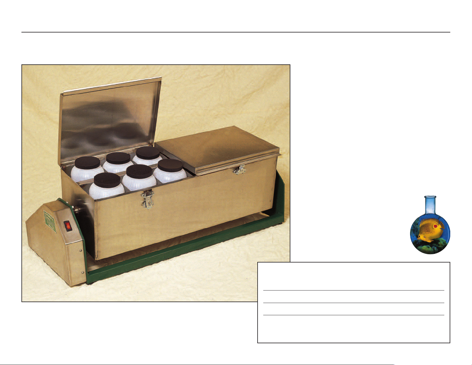
The large 6.25" x 6.25" x 12.75"
stainless steel compartments on the LE
rotator accommodate most zero space
extractors and many styles of glass and
plastic bottles. The box-style design
offers a greater degree of safety than
other rotator designs.
The 12-position sample box is
constructed of 14-gauge stainless steel
welded and reinforced at all joints. The
drive shaft is a full 1" in diameter to
prevent any breakage, even with offcenter loads. Glass bottles containing
extraction fluid are shielded within the
stainless steel box, not rotating exposed
in your laboratory.
Rotators use Brother
120VAC (also available in 240VAC)
high-efficiency gear motors with selflubricating drive chains. Brother gear
motors are designed in accordance with
today’s most stringent industrial
standards to ensure longer service life
and increased reliability. These allhelical gears are among the quietest
available and have the very high surface
hardness required to ensure extended
wear resistance commonly associated
with EPA Method 1311.
®
1/6hp, 60Hz,
A self-lubricating chain prevents
slippage and requires no maintenance.
Precise, constant speed control
(30rpm) is maintained during long
hours of continuous operation.
The advantage that stands out with
the LE Heavy Duty Rotator is the quiet,
consistent and dependable service this
well designed power system delivers.
Accessories available for use with
the Heavy Duty LE Rotator include:
-
Compartment spacers/cushions
-
A variety of bottles and extraction
devices
Heavy Duty LE1002/LE1003
Rotator Product Warranty:
The Environmental Express Heavy Duty LE
Rotators are warranted against defects in
materials and workmanship, when used in
accordance with applicable instructions for the
period of one year from the date of shipment.
This warranty extends to parts and labor, applies
only to damage or failure caused by normal
laboratory use and is limited to product repair.
If Environmental Express is unable to repair the
Rotator, the customer may, at his or her option,
receive a replacement or a full refund.
Environmental Express makes no other warranty,
expressed or implied, for this product with
respect to fitness for a particular use or any
other matter. Environmental Express is not liable
for any consequential or compensatory damages
arising from the use of, or in conjunction with
this product. The maximum liability shall be the
invoice price of the product.
Safety Precautions:
Please read this manual carefully. It contains valuable information that will
prevent damage to the machine and/or serious bodily injury to personnel.
CAUTION
-
Always stay clear of rotating parts!
-
Failure to read and practice these safety
precautions could result in serious damage to
equipment and/or cause serious bodily injury to
operating personnel.
-
Do not attempt to use this equipment if you are
not familiar with the dangerous characteristics it offers.
-
This unit can develop significant torque. IT CAN HURT
YOU. Do not allow clothing or long hair near an
operating unit.
-
Never remove protective guards. Failure to comply
could cause serious damage to equipment and/or
serious bodily injury — including electrocution.
-
All repairs should be performed by a qualified
technician.
1 • Environmental Express
www.environmentalexpress.com
Page 3

Basic Operating Procedures
Heavy Duty LE Rotator Manual
Please read this manual before plugging in your unit.
Placement of Your LE Rotator:
t is important that your rotator is
situated in a safe, cool and dry
I
environment. The rotator weighs in
excess of 172 pounds. With this in
consideration, a solid structure such as
a counter top is an ideal location. If a
sturdy counter top is not available
place the unit directly on the floor.
The unit should be placed far enough
away from the front edge of the
counter to avoid possible contact with
passersby.
Caution: Never allow the power cord
to come into contact with rotating
components.
The use of extension cords should
be avoided if at all possible. The unit
should be placed close enough to a
grounded electrical outlet to enable use
of the factory power cord. If it is
impossible to avoid use of an extension
cord, make sure that you use a threeprong 14 AWG cord (or larger, i.e. 12
AWG) only. Using too small of an
extension cord will cause the cord to
become very hot thus becoming a fire
risk. Failure to comply could also cause
serious damage to the electrical
components of your rotator and would
void your warranty.
Basic Operating Procedures:
nce you have read this manual
thoroughly, ensure that the power
O
switch is in the OFF position and
that all obstacles and personnel are
clear of the unit. Plug the power cord
into a 120VAC (LE1002) or 240VAC
(LE1003) outlet, as described in the
previous section. Turn the unit on to
confirm operation. The switch should
always glow amber during operation.
Refer to the troubleshooting section of
this manual if the unit does not operate.
To load the compartments, turn the
latch counterclockwise to release
tension. Open the lid and load the
compartments to suit your needs.
Caution:
It is important to offset your load
(Refer to figure 1). For example, when
you are loading a 12-place unit, and
you have 6 bottles to load, avoid
putting all six bottles on the front or
back side of the box. Put the first bottle
in the back left compartment, the
second bottle in the second front
compartment, the third bottle in the
third back compartment and so on.
By doing this, you will reduce the
stress on the geared components thus
allowing your rotator to last much
longer.
Figure 1, proper
loading sequence
Rotator Specifications—
Dimensional Information: LE1002/LE1003 (12-place) 24.5"W x 43.6"L
Weight: 172lb.
Shipping Weight: 262lb. Delivery by truck only.
Electrical: Gearmotor LE1002 — Brother 1/6 HP/120VAC/60Hz/1.7AMP (FL)
Gearmotor LE1003 — Brother 1/6 HP/240VAC/50Hz/.8 AMP (FL)
Switch/Circuit Breaker — 15AMP Integral Unit
Capacitor LE 1002 — 120 VAC/24µF (+10 to -5%)
Capacitor LE1003 — 240 VAC/6µF (+10 to -5%)
Bearings: NTN
Drive Components: Synchronous Self Lubricating Chain
Rotating Box and Guard: Custom Fabricated from type 304 Stainless Steel.
Frame: Custom Fabricated from Mild Steel Components.
®
Sealed Ball, Maintenance Free, Heavy Duty Flanged.
Synchronous Timing Sprockets
Paint and Prime Coat, Chemical Resistant Two-Part Industrial Enamel.
2 • Environmental Express
Call 1.843.881.6560
Page 4

Troubleshooting Guide
The unit is plugged into the wall outlet, the
switch is on but nothing happens:
1. Is wall outlet “hot”? Check the breaker box and
try plugging another electrical device into the
outlet to see if it works.
2. Does the switch on the unit light up? If not, the
internal circuit breaker may have tripped. Try
turning the switch off and back on to reset the
circuit breaker. If the switch illuminates, but the
unit still does not operate, unplug the unit
immediately and call 1.843.881.6560 or
1.800.343.5319 for technical support. Only a
competent electrician should attempt to work on
the electronics of this unit. Failure to comply
may void your warranty.
The motor runs but the box does not rotate:
1. There could be several possibilities for this;
stripped gears in the gearbox, a broken chain or
loose set screws on pulleys are a few things to
suspect. If this problem has occurred, please
contact technical support at 1.843.881.6560 or
1.800.343.5319. Please do not attempt to retrofit
any components. (If your unit is still under
warranty, you may be entitled to parts at no
expense to you.)
Rotator Assembly Drawing
Heavy Duty LE Rotator
Detail A
5
Detail B
Rotator
Side View
See Detail A and Detail B, page 4.
The unit makes noise while rotating:
1. After continued use over several years, it may be
necessary to grease the two bearings. This is a
very simple process. Unplug the unit, insert the
grease gun fitting over the zerk nipple located on
the bottom of each flanged bearing. Pump the
grease gun until you notice a slight trace of
grease discharge out of the bearing insert. This
should correct the problem.
3 • Environmental Express www.environmentalexpress.com
Page 5

Rotator Assembly Drawings Heavy Duty LE Rotator Manual
Detail A
Detail B
Parts List:
Item # Description
1 Extractor Box
2 Belt Guard
3 Rotator Frame
4 Motor
5 Drive Chain
6 Circuit Breaker Switch
7 Leveling Feet
8 Power Cord
9 N/A
10 15 Tooth Sprocket
11 3/4" Flange Bearing
12 3/8" - 16 Socket Cap Screw
13 12 - 10 3/4" Taper Lock Bushing
14 5/16" - 18 Socket Cap Screw
15/16 5/16" - Flange Nut
4 • Environmental Express Call 1.843.881.6560
Page 6

Drive Chain Adjustment and Maintenance
Maintaining proper chain tension:
The chain needs to be inspected routinely to
maintain proper chain tension. If the chain
develops 1/4" or more of slack it should be
tightened using the procedure below.
Steps to loosen chain:
1. Loosen the jam nuts using a 7/16" wrench.
2. Loosen the adjusting bolts, which are the bolts
that hold tension against the motor, with a 3/16"
allen wrench.
3. Loosen the four bolts on the motor using a 1/4"
allen wrench so that the motor can be slid over.
Steps to tighten chain:
1. Tighten the adjusting bolts with a 3/16" allen
wrench which actually pushes the motor back
into position. The chain should have no slack.
Rotator Assembly Drawing with Drive Chain
Heavy Duty LE Rotator
Drive Chain
2. Tighten the jam nuts using the 7/16" wrench
so that the motor will not slide out of position.
3. Tighten the bolts on the motor using the 1/4"
allen wrench.
Rotator
Side View
with Drive Chain
5 • Environmental Express www.environmentalexpress.com
Page 7

Wiring Schematic (shown for single phase 120VAC) Heavy Duty LE Rotator Manual
6 • Environmental Express Call 1.843.881.6560
 Loading...