

Page 1
M
T
H o t B l o c k
D i g e s t i o n S y s t e m
O p e r a t i o n & I n s t r u c t i o n M a n u a l
E N V I R O N M E N T A L E X P R E S S
800.343.5319 or 843.881.6560
n
Fax 843.881.3964
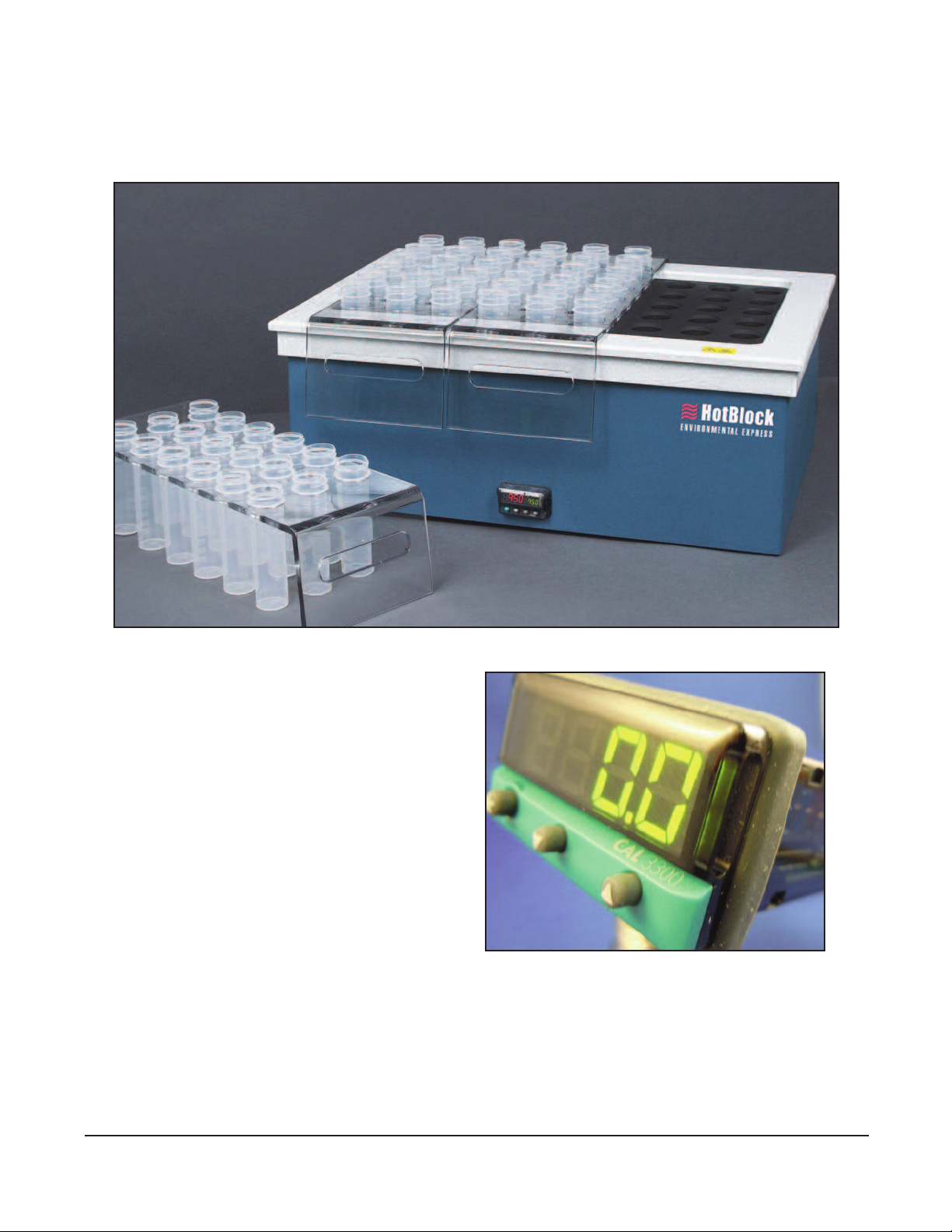
CAL3300 Controller
n
www.environmentalexpress.com
Copyright, Environmental Express, Inc., January 2011
Page 2

Contents HotBlock Operation Guide
Contents 1
Declaration of Conformity / Record Your Product Information 2
Warranty Information 3
About Your HotBlock
- Part Numbers / Model Information / Specifications 4-6
Getting Started
- Installation Requirements / General Information 7
- Controller Settings 8-10
- Adjusting the Temperature of Your HotBlock 11
Safety Information 12
Parts List 13
Circuitry Diagram (With Alarm) 14
Circuitry Diagram (Without Alarm) 15
Troubleshooting Guide 16-18
EPA Approval Letter 19
Environmental Express HotBlock Manual, copyright Environmental Express, Revised September 2010.
Environmental Express •1Call 1.800.343.5319
Page 3

Declaration of Conformity HotBlock Operation Guide
The manufacturer,
Environmental Express
490 Wando Park Blvd., Mt. Pleasant, SC 29464
declares that the following products:
HotBlock CatalogTNumbers- SC196, SC154, SC150, SC151, SC100, and C6002
Standard for Safety Electrical Equipment for Measurement, Control, and Laboratory Use; Part 1 General
Requirements, UL 61010-1, CAN/CSA-C22.2 No. 61010-1, 2nd Edition, Issued 12 July, 2004 with revisions through
and including 28 October, 2008; Equipment for Measurement, Control, and Laboratory Use Part 2-010: Particular
Requirements for Laboratory Equipment for the Heating of Materials, IEY 61010-2-010, 2nd Edition, Issued 1 June,
2003, SafetyRequirements for Electrical Equipment for Measurement, Control, and Laboratory Use - Part 2010:Particular Requirements for Laboratory Equipment for the Heating of Materials, CSA C22.2.61010.2.01
Signed:
Dennis Pope, Chief Executive Officer
PRODUCT INFORMATION:
Catalog # Date of Purchase
HotBlock Serial #
(Please record the serial # of your HotBlock here for easy reference. Your serial # is located on the back of your block.)
Environmental Express • 2www.environmentalexpress.com
Page 4

HotBlock™LIMITED WARRANTY
he Environmental Express HotBlock is warranted against defects in materials and workmanship when used in
accordance with applicable instructions, for a period of one year from the date of shipment. This warranty
T
extends to parts, labor, and any approved transportation charges. This warranty applies only to damage or failure
caused by normal laboratory use. The warranty is limited to product repair. If Environmental Express is unable to
repair the HotBlock, the customer may, at his or her option, receive a replacement unit or a full refund. Operating the
HotBlock at temperatures higher than 150°C will void the warranty.
Environmental Express makes no other warranty, expressed or implied for this product with respect to merchantability,
fitness for a particular use or any other matter. Environmental Express is not liable for any consequential or compensatory
damages arising from use of, or in conjunction with this product. The maximum liability shall be the invoice price of this
product.
REPAIR POLICY— Under Warranty Repair:
If the HotBlock should fail to operate within the warranty period (one year from date of shipment) Environmental
Express will repair it and ship it back to the customer at our expense. The remainder of the warranty period will be
honored from the original ship date. Environmental Express will bear the cost of ground transportation both to and
from the customer’s location, and bear the cost of any parts, labor and cleanup required. However, if it is determined
that the damage to the HotBlock was caused by negligence or improper use, this warranty will not apply. The
warranty is also void if the system is used beyond its intended purpose or in the event of any unauthorized repair. In
such cases, reasonable and customary repair charges will apply. Repair charges will be quoted prior to work being
done.
REPAIR POLICY— Out of Warranty Repair:
If the HotBlock fails after the warranty period has lapsed, the repair procedure is as follows:
First, notify an Environmental Express Technical Service Representative of product’s failure and place an order for
repair. Whenever possible, our customer service technician will walk you through possible troubleshooting scenarios
which may enable you to repair your block on site. (See the troubleshooting section of this manual, pages 12-14).
If on site repair is not possible, the customer may return the non-working unit to Environmental Express using
appropriate shipping containers and insurance. Repair charges will be assessed and estimated prior to work being
done. Repair charges will include all freight costs as well as reasonable and customary charges for parts and labor.
Loaner HotBlocks MAY be available during the repair period. There are only a limited number of these units.
A reasonable charge for “cleanup” will be charged if a loaner is issued. The customer will be responsible for all
shipping charges associated with a loaner unit.
E N V I R O N M E N T A L E X P R E S S
490 Wando Park Blvd., Mt. P leasant, S C 29464
n
800.343.5319 or 843.881 .6560
www.environmentalex press.co m
Environmental Express • 3Call 1.800.343.5319
Page 5
About Your HotBlock
TM
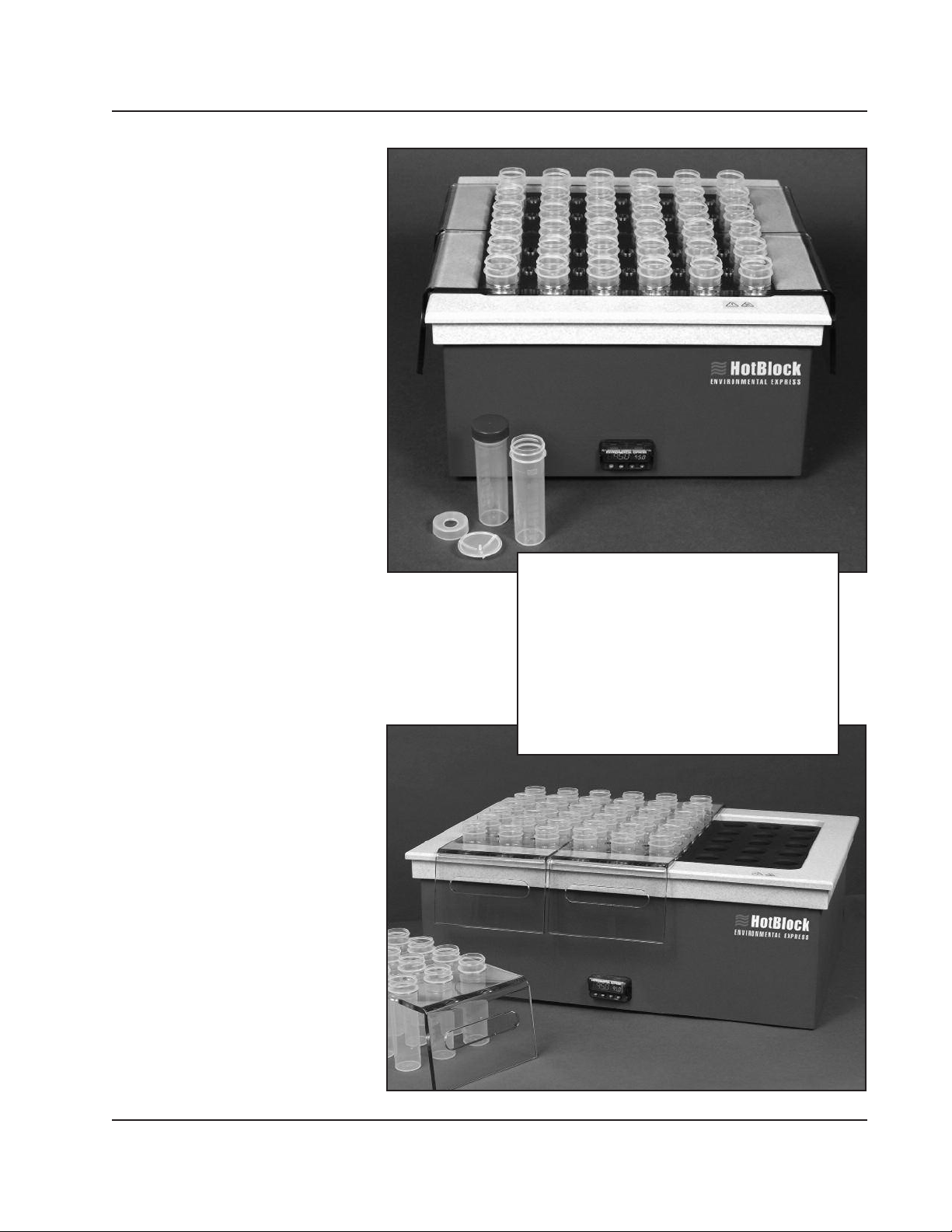
50mL Sample
36-well HotBlock
he SC100 with its 36-sample
capacity was the first model in the
T
HotBlock line and is used daily in
hundreds of laboratories around the
world. All electronics are self contained
and isolated in a separate compartment
below the block — no need for a
separate controller and clumsy cables.
For use with the SC100, we recommend
our disposable SC475 50mL digestion
vessels shown on page 15. This energy
efficient unit draws a maximum of 1080
watts and generates very little waste
heat. The SC100 is supplied with two
18-place polycarbonate racks (catalog #
SC200) to facilitate the loading and
unloading of samples.
Catalog # SC100,
36-Sample Capacity
50mL Sample
54-well HotBlock
HotBlock Operation Guide
Specifications: SC100 SC154
Footprint: 15" x15" 15" x 21.5"
Crated Size: 23" x 23" x 17" 26" x 23" x 17"
Weight: 43 lb. 59 lb.
Shipping Weight: 58 lb. 78 lb.
Electrical: 120VAC*, 9 A 120VAC*, 14 A
Sample Capacity: 36 54
Nominal Sample Size: 50mL 50mL
Temperature Range: to 150°C to 150°C
Thermocouple: Type K Type K
All HotBlocks are also available in 240V.
he large capacity SC154 HotBlock
digests up to 54, 50mL samples in
T
a 15" X 21.5" footprint. This model
comes with three 18-place
polycarbonate racks (catalog # SC200),
allowing the operator to load or unload
18 samples at once. We recommend our
disposable SC475 digestion vessels
shown on page 15. The compact size of
the SC154 allows it to fit comfortably
inside our HEPA-filtered AirLiteTMfume
enclosure. All HotBlock models are
equipped with the Safe-SampleTMfeature
to prevent runaway temperatures in
event of an electronic failure.
Catalog # SC154,
54-Sample Capacity
Environmental Express •4www.environmentalexpress.com
Page 6

T
A
b
o
u
t
Y
o
u
r
H
o
t
B
M
l
o
c
k
HotBlocks for
100mL Samples
or larger sample size, the SC150 and
SC151 HotBlocks are designed for
F
the digestion of 100mL samples.
Both blocks use disposable, graduated
125mL screw-cap polypropylene vessels.
Note that with the larger digestion
vessels faster sample reduction may
occur due to greater surface-to-volume
ratio.
The SC150 digests up to 25 samples
simultaneously and comes with two
polycarbonate racks, a 15-place rack
paired with a 10-place rack, to facilitate
loading and unloading of samples. The
SC151 accommodates up to 35 samples
and comes with a 15-place rack and two
10-place racks. Digestion cups and
accessories for 100mL blocks are shown
on page 17.
Catalog # SC150,
25-Sample Capacity
Catalog # SC151,
35-Sample Capacity
H
o
t
B
l
o
c
k
O
p
e
r
a
t
i
o
n
The SC151 HotBlock
is a 35-well Block for 100mL Samples.
Specifications: SC150 SC151
Footprint: 15" x15" 15" x 21.5"
Crated Size: 23" x 23" x 17" 26" x 23" x 17"
Weight: 42 lb. 59 lb.
Shipping Weight: 54 lb. 65 lb.
Electrical: 120VAC, 9A 120VAC, 13A
Sample Capacity: 25 35
Nominal Sample Size: 100mL 100mL
Temperature Range: to 150°C to 150°C
Thermocouple: Type K Type K
All HotBlocks are also available in 220V.
G
u
i
d
e
Call 1.800.343.5319
SC150 HotBlock is a 25-well Block for
100mL Samples.
Environmental Express •5
Page 7

About Your HotBlock
TM
50mL Sample
12-well HotBlock
he 12-place HotBlock was designed
as a component for our SimpleDist
T
System but doubles as a compact
HotBlock for metals digestions. Digest
small batches of 50mL samples in a
compact footprint. Each block comes
with a 12-place polycarbonate transfer
rack, C6050.
Catalog # C6002,
12-Sample Capacity
15mL Sample
96-well HotBlock
HotBlock Operation Guide
C6002 Specifications—
Footprint: 8.55" x 18.5"
Crated Size: 22" x 19" x 13"
Weight: 30 lb.
Shipping Weight: 35 lb.
Electrical: 120VAC, 13A
Sample Capacity: 12
Nominal Sample Size: 50mL
Temperature Range: to 150°C
Thermocouple: Type K
All HotBlocks are also available in 220V.
he SC196 HotBlock is for the
digestion of 15mL samples and has a
T
96 sample capacity. The
recommended digestion vessel, SC415,
has a total volume of 18mL and is
graduated in 5mL increments. Originally
designed for the mining industry, the
SC196 has proven effective for
applications requiring reduced sample
size, higher throughput and lower waste.
The external parts of this HotBlock are
made of corrosion-resistant materials
including Teflon®, Kydex®and graphite.
The heating source is a solid block of
Teflon-coated graphite. The SC196 has
the same safety and thermal controls as
other HotBlock models and has a
temperature range of ambient to 150°C.
The SC196 comes with three
polycarbonate racks that hold up to 32
samples each to facilitate loading and
unloading samples.
Catalog # SC196
96-Sample Capacity
SC196 Specifications:
Footprint: 15" x 21.5"
Crated Size: 26" x 23" x 17"
Weight: 59 lb.
Shipping Weight: 80 lb.
Electrical: 120VAC*, 14 A
Sample Capacity: 96
Nominal Sample Size: 15mL
Temperature Range: to 150°C
Thermocouple: Type K
All HotBlocks are also available in 240V.
Environmental Express •6Call 1.800.343.5319
Page 8

Installation, General Information HotBlock Operation Guide
Environmental Express HotBlock
Environmental Express HotBlocks provide an efficient method of digesting and storing water, wastewater, soil and sludge
samples for metals analysis. These innovative digestion systems allow samples to be digested in a corrosion-free
environment. In addition, samples are handled in a small area with minimal radiant heat loss. Users should be aware of
potential dangers from heating certain types of compounds. Such hazards may include explosion or the release of toxic or
flammable gases
™
Unpacking Your HotBlock
Remove the HotBlock from the shipping container by lifting from the bottom of the block. The lid should not be used for
lifting. Your HotBlock is shipped with metal screws securing the bottom panel. The metal screws must be removed before
operating your HotBlock. Remove the metal screws and replace them with the PVC screws and rubber feet included with
your shipment. The corrosion-resistant PVC screws and rubber feet are designed to secure the bottom plate.
IMPORTANT: DO NOT OVER TIGHTEN THE PVC SCREWS!
Definitions/Markings
Each HotBlock displays certain markings and symbols. All personnel working with the HotBlocks should have an
understanding of the following symbols and definitions:
Definitions and Symbols:
n
V = voltage
n
~ = alternating current
n
Hz = frequency
n
A=amperes
This symbol means “Caution
Hot Surface”. The surface of
the HotBlock may be too hot
to safely touch with bare
hands.
This symbol means “Read
and become familiar with
instructions before
operation of instrument”.
Installation Requirements
Locate the HotBlock under a fume hood with a minimum face velocity of 100fpm, and allow a minimum of 2" of space on
all sides. The following environmental conditions should be observed:
n
Ambient temperature range: 5-30°C
n
Ambient relative humidity: 0-90%RH
n
Altitude: sea level to 2500 meters
HotBlocks are rated as Pollution Degree 2 and Installation Category 2.
Electrical Requirements
n
Required Voltage: 120 volts, ~60Hz, 15A
(all HotBlocks are also available in 240V with CE mark)
Power should not vary greater than±10%. Use the supplied heat-resistant power cord or equivalent to connect to the
power supply
For safety reasons, a separate power receptacle should be provided for each unit in the system. Do not use extension
cords or outlet adaptors. Make certain that power outlets are earth-grounded at the grounding pin.
See individual specifications for each HotBlock model, pages 4-6.
www.environmentalexpress.com
Environmental Express • 7
Page 9

Controller Settings HotBlock Operation Guide
Environmental Express • 8www.environmentalexpress.com
Page 10

Controller Settings HotBlock Operation Guide
Environmental Express • 9www.environmentalexpress.com
Page 11

Controller Settings HotBlock Operation Guide
Environmental Express • 10www.environmentalexpress.com
Page 12

Adjusting the Temperature of Your HotBlock
TM
HotBlock Operation Guide
HotBlock Temperature Settings:
The pre-set factory “Control Point” temperature is 115°C. Factory tests have shown that this temperature is “sea level safe.”
Liquids in uncovered, polypropylene tubes should not boil at this setting. If watch glasses are used, this setting should be
lowered to avoid boiling. The block temperature should be optimized for the specific digestion conditions. PLEASE NOTE that
the block temperature is different than the temperature of the liquids being digested. The temperature of the liquid contents of
the digestion cup will vary with:
A. The material being digested.
B. The number of samples being digested.
C. The air movement of the digestion area.
D. The addition of a watch glass.
Note: The maximum use temperature of the polypropylene cup is 130
not the temperature of the sample. Sample temperature will almost always be 5-15less than the display temperature.
C. Also please note that the temperature display is
Adjusting the Temperature of Your HotBlock:
1. Turn the HotBlock on and wait until the display shows the current block temperature.
2. Press and hold the ✱ key. The display wills how the set point temperature. The temperature can be cahnged
to the desired valued by pressing the ▲or ▼keys while pressing the ✱ key.
Tuning Your Hotblock:
Each Hot Block should be tuned at the temperature at which it is to be operated. Tuning enables the Hot Block to achieve
its set point tempera- ture without any overshoot. Tuning of the Hot Block is done at the factory at 115°C. If the block is
operated at a temperature significantly different from 115°C, it may be advisable to re-tune the block to prevent
overshooting the set point temperature. To tune the Hot Block with the CAL 3300 controller, follow these steps:
1. Tuning should be started when the block is near room temperature.
2. Turn the Hot Block off and back on.
3. Wait until the block displays the current temperature, then press the and keys together until “tune” appears on
the display.
4. Press the and key together to change the display from “off” to “on”.
5. Press the and keys together until the display flashes once.
6. It is now in autotune mode. The display will alternate between the rising temperature and “tune” until it reaches
your set point.
7. After the unit has reached your set point temperature, repeat steps 3 through 5, this time changing the “tune”
mode from “on” to “off” in step 4.
The block is now tuned. No other action by the operator is required. The block may be turned off and on and the tuning
will be set.
Safe-SampleTMTemperature Protection:
Your HotBlock is protected from runaway temperatures by a fail-safe alarm system. In the unlikely event that the heating
system fails to respond to the controller, the Safe-SampleTMsystem will automatically shut the system off and sound an
audible alarm. This alarm sequence occurs if the actual temperature of the block reaches a temperature that is fifteen
degrees higher than the set point temperature. If this should occur, the HotBlock will stop heating, preventing the loss of
samples. The HotBlock must be turned off, then turned back on to reset the alarm. If the alarm sounds, see the trouble
shooting section of this manual, pages 12-14
Call 1.800.343.5319 Environmental Express • 11
Page 13

Safety Information HotBlock Operation Guide
Potential Hazards:
The HotBlock should only be operated by properly trained personnel using standard laboratory safety practices.
Use extreme caution when operating the HotBlock. Plastic and graphite surfaces of the HotBlock may be too hot to safely
touch with bare hands.
The HotBlock contains electrical circuits and devices and compounds operating at dangerous voltages. Contact with these
circuits, devices and components can cause serious injury or painful electric shock.
Proper grounding is essential to avoid a potentially serious electric shock hazard. Ensure that there is an internal ground
connection between the metal base of the system and the 3-pin, earth-grounded receptacle.
For safety reasons a separate power outlet receptacle should be provided for each unit in the system. Do not use extension
cords or outlet adaptors. Make certain each power outlet is earth-grounded at the grounding pin.
See individual block specifications for power requirements, pages 4-6.
Application of the wrong supply voltage can create a fire hazard and a potentially serious shock hazard, and could
seriously damage the HotBlock system. See specifications for individual HotBlocks.
Users should be aware of potential dangers from heating certain types of compounds. Such dangers may include
explosion or the release of toxic or flammable gases.
Always lift the HotBlock from the bottom of the unit.
Maintenance:
Any service inquiries should be directed to Environmental Express Technical Service Department. After each use, clean exterior
surfaces with a damp sponge to remove acid residue. For acid spills, sponge with a diluted solution of sodium bicarbonate
followed by distilled water. Acid that is spilled directly into the digestion wells should be neutralized and removed. Before using
any cleaning or decontamination methods except those recommended, check with Environmental Express to confirm the
proposed method will not damage your HotBlock.
Avoid excessive spills, as liquid allowed to overflow into the HotBlock casing can severely damage electronic components.
www.environmentalexpress.com
Environmental Express • 12
Page 14

HotBlock Replacement Parts HotBlock Operation Guide
Part Description Part Number
Power module (plug receptacle)w push button switch SC941
Power Cord- heavy duty SC958
Environmental Express Controller SC945
12" X 12", 120V, silicone rubber, etched-foil heater mat for models SC100 & SC150 SC951
12" X 12", 240V, silicone rubber, etched-foil heater mat for models SC100-240 & SC150-240 SC951-240*
110/220V, 25A solid state relay SC952
Type K Thermocouple SC953
Terminal board SC955
Ceramic fiber insulation for models SC100 & SC150 SC959
14" X 14" Powder-coated aluminum bottom for models SC100 & SC150 SC963
12" X 18", 120V, silicone rubber, heater mat for models SC154 and SC196 & SC151 SC966
12" X 18", 240V, silicone rubber, heater mat for models SC154-240 SC196-240 & SC151-240 SC966-240*
12” X 8” 120V silicone rubber heater mat for model C6002 (12-Place Block) C6300
Fail-Safe Relay SC968
Alarm Buzzer SC969
Ceramic fiber insulation for models SC154, SC196 and SC151 SC970
14" X 19", powder-coated aluminum bottom for models SC154, SC196 and 151 SC971
PVC screw for rubber foot SC964
Rubber foot SC976
*for HotBlocks shipped outside the United States and Canada
Call 1.800.343.5319
Environmental Express • 13
Page 15

HotBlock Circuitry Diagram with Alarm HotBlock Operation Guide
Call 1.800.343.5319
Environmental Express • 14
Page 16

HotBlock Circuitry Diagram without Alarm HotBlock Operation Guide
Call 1.800.343.5319
Environmental Express • 15
Page 17

Troubleshooting Guide HotBlock Operation Guide
lease consult the following troubleshooting guide if you experience problems with your HotBlock. See wiring
schematic (page 14-15) for component identification. If you are unable to resolve the problem or if replacement
P
components are necessary, please contact technical service at 1-800-745-8218 as component replacement varies in
degree of difficulty. We recommend that only qualified personnel attempt troubleshooting electrical components.
When the HotBlock is initially powered on, the controller will cycle through a self-test sequence. It will then display the
current temperature and begin heating until it reaches your set point temperature, where it will hold until the unit is
powered off. The set point may be changed at any time. A change in the controller’s factory default settings or a failed
component may cause the HotBlock to perform unsatisfactorily or render it inoperable.
The controller digital display will not illuminate.
There are two possible reasons that your controller will not illuminate.
n
The controller is not getting voltage or;
n
The controller itself has failed internally.
The problem can be effectively diagnosed by determining if the controller is or is not getting voltage using the
following steps:
1. Confirm that the power cord is plugged securely into the HotBlock receptacle and a working outlet.
2. Confirm that the switch is in the “on” position. Press button on the back of HotBlock.
3. Check the fuse located in the power module:
a) Locate the fuse drawing indented into the power module next to the socket.
b) Using a small screwdriver, pry open the fuse compartment cover.
c) Examine the exposed fuse for a break in the filament and if necessary, check for continuity using a volt-meter.
d) If the fuse is determined to be blown, replace it with the spare fuse located in the slide-out compartment
beneath the operating fuse.
Caution: This procedure is a potential electrical hazard and should only be performed by qualified personnel.
4. Inside the HotBlock, check voltage leading from the power module to the controller:
a) Remove the bottom panel of the HotBlock by unscrewing the rubber feet.
b) On the back of the controller, locate the black wire at terminal 6 and white wire at terminal 8.
c) Set your volt-meter on AC voltage.
d) Touch your red lead to the exposed white wire and black lead to the exposed black wire.
e) If your volt-meter reads 110-122V, the controller is receiving power but has failed internally. It must be
replaced (see parts list, page 13).
f) If your volt-meter registers less than 110-122V, using step d above check the black and white wires at
the terminal board and then at the power module to determine if there is a faulty connection.
The audible alarm has sounded immediately after powering on and the HotBlock will not heat.
There are two possible causes for your HotBlock to sound the alarm immediately after the controller cycles through
the self test. These are:
n
Your set point has been set to a value (≥) 15° less than ambient or current set point temperature. Turn the set
point to within 15° of the actual temperature (blue numbers)
n
There the controller is faulty. Call Environmental Express at 1-800-343-5319 for more information
Call 1.800.343.5319
Environmental Express • 16
Page 18

Troubleshooting Guide HotBlock Operation Guide
The temperature has overshot the set point and the audible alarm has sounded.
The function of the fail-safe system is to cease heating of the HotBlock in the event of a set point overshoot of
15°C and to alert the technician of the incident. The HotBlock can be “fooled” into fail-safe mode if the set point
is manually changed to a value ≥15° below your current temperature. However, the primary cause for the runaway
temperature is a faulty relay that has exceeded its useful life. You may troubleshoot the relay by following these
steps:
Caution: This procedure is a potential electrical hazard and should only be performed by qualified personnel.
1. Power off your HotBlock.
2. Remove the bottom panel of the HotBlock by unscrewing the rubber feet.
3. Power the HotBlock on and allow it to overshoot your set point temperature.
4. Locate the solid state relay mounted to the bottom panel.
5. Set your volt-meter to measure AC voltage.
6. Touch your red lead to (white wire) of the solid state relay and touch your black lead to a ground
source (e.g., the green/yellow wire from the power module or an empty terminal on the terminal board).
7. If your volt-meter reads 110V-122V, then the relay is stuck in the “closed” position and it must be replaced
(see parts list, page 10).
The HotBlock will not heat beyond ambient temperature.
A HotBlock that will not heat beyond ambient temperature typically has a failed relay, heater mat or
controller.
n
Relay—To test the relay, the output voltage must be determined with a volt-meter.
Caution: This procedure is a potential electrical hazard and should only be performed by qualified personnel.
To measure the relay voltage, follow these steps:
1. Remove the bottom panel of your HotBlock by unscrewing the rubber feet.
2. Locate the solid state relay mounted to the bottom panel.
3. Set your volt-meter to measure AC voltage.
4. Touch your red lead to (white wire) of the solid state relay and touch your black lead to a ground
source (i.e., the green/yellow wire from the power module or an empty terminal on the terminal board).
5. If your volt-meter does not read 110V-122V, then the relay has stuck in the “open” position and it must be
replaced (see parts list, page 13).
n
Heater Mat—To test the heater mat, the resistance (ohms) must be determined with a volt-meter. It is
recommended that your heater mat be replaced if it measures 25 ohms (W) or greater. It is also
recommended that the thermocouple and insulation be replaced as well, both are inexpensive parts that are
not easily accessible otherwise.
To measure your heater mat resistance, follow these steps:
1. Power off your HotBlock and remove the bottom panel of your HotBlock by unscrewing the rubber feet.
2. Locate and disconnect the white wire connected to the relay and an identical wire on terminal #2
www.environmentalexpress.com
Environmental Express • 17
Page 19

Troubleshooting Guide HotBlock Operation Guide
of the terminal board (note: terminal #2 of the terminal board contains 3 white wires. To ensure you have the
correct wire, trace it back and ensure it originates from the graphite portion of your HotBlock.
3. Set your volt-meter to measure ohms ( W )
4. Touch the red lead to one of these wires and touch the black lead to the remaining wire.
5. If your reading is “OL” (over limit) or a value greater than 25 ohms, then the heater mat has failed and it must
be replaced (see parts list, page 13).
n
Controller—To test the controller, the output voltage must be determined with a volt-meter. To measure
voltage from the controller, follow these steps:
Caution: This procedure is a potential electrical hazard and should only be performed by qualified personnel.
1. Remove the bottom panel of your HotBlock by unscrewing the rubber feet.
2. Locate the solid state relay mounted to the bottom panel.
3. Set your volt-meter to measure DC voltage.
4. Touch the red lead to terminal (RED) and the black lead to terminal (BLUE) of the solid state relay.
5. Your volt-meter should read 3V-16V.
6. If your volt-meter does not read 3V-16V, perform steps 3 and 4 on the red and blue (5 and 6) wires at the
terminal board and controller to determine if there is a faulty or loose connection.
7. If you do not get a reading of 3V-16V at terminals 3 (red) and 4 (blue) of the controller then the controller
has failed internally and it must be replaced (see parts list, page 13).
The temperature controller is performing erratically or displays an error message.
The temperature controller is flashing Er.L Attn- Thermocouple Fault
First reset default settings
1. Hold the up and down arrow buttons for six seconds until Ai Set appears
2. Hold the down arrow until glbl set is in the window
3. Press the green advance key to enter
4. Continue pressing the green advance key until none user appears.
5. Press the down arrow key until Set1 user appears.
6. Pressing the advance key will restore default settings.
To troubleshoot the thermocouple, follow these steps:
1. Power off your HotBlock.
2. Remove the bottom panel of your HotBlock by unscrewing the rubber feet.
3. Locate the thermocouple wires at terminals 1 (yellow) and 2 (red) of the controller and remove using a small
screwdriver.
4. Cut the exposed ends of the two wires.
5. Strip 1/4" of insulation from each wire and reconnect them to the appropriate controller terminal and tighten.
6. Power on your HotBlock.
7. If your display continues to flash Er.1 Attn- the thermocouple is faulty and must be replaced
(see parts list, page 13).
Call 1.800.343.5319
Environmental Express • 18
Page 20

EPA Approval Letter HotBlock Operation Guide
Call 1.800.343.5319
Environmental Express • 19
 Loading...