

Page 1
Operation Manual
AutoBlock Serial Number: ________________________
Electrical Box Serial Number: ______________________
490 Wando Park Blvd., Mt. Pleasant, South Carolina 29464
800-343-5319 or 843-881-6560 / Fax 843-881-3964
ENVEXP.COM
5528COVER rev3 9/10/09
Page 2

TABLE OF CONTENTS
page
Introduction
4 What’s Included
4 Uncrating
4 Unpacking
Installation
5 Preparing the AutoBlock lll
5 Space & Weight Requirements
5 Ventilation
6 Front Door Installation
6 Pump Compartment Door Installation
6 Install Reagent Line
7 Reagent Line Assembly
7 Placement of Reagent Rack
7 AutoBlock Reagent Port
8 Install Drain Line & Carboy
8 Electrical Box Installation
System Overview
9 Reagent Flow Path
10 General Cleaning
Touch Screen Controller
11 Main Screen Functions
11 Sensor Indicators
12 Abort
12 Temperature Readouts
13 On Board Keyboard
Start Up Instructions
14 Power Switch & Load Software
14 Test Injection System
15 Sample Injection Tubing / Pump Calibration
15 Maintenance
15 Sensor Validation
Manual Mode
16 Rack Movement
17 Home
17 Fan
17 Graphite
18 Arm
18 Inject
ENVIRONMENTAL EXPRESS
For technical support call 800-745-8218 or send email to INFO@ENVEXP.COM
5528INDEX rev 3 2 9/10/09
Page 3

TABLE OF CONTENTS
page
Run Mode
19 Rack A / Rack B / Rack C
20 Pause Button
20 Main Screen Abort Button
Program Mode
21 Heat
21 Inject
22 Wait
22 Cool
22 Pause
22 Delete
23 Open
23 Save
23 New
23 Edit
24 Import / Export Method
24 Export Log
25 Syntax Errors
Service Mode
26 Setup Reagents
27 Calibrate Temp
27 Calibrate Pump
30 Maintenance
30 Options
31 Supplies
32 Supplies List
33 Exit
Warranty
34 90-day Warranty
34 9-month Warranty
34 Warranty Disclaimer
34 Charges Not Covered by Warranty
34 How the Warranty Works
Repair
35 Repair Approval
35 In-Lab Troubleshooting & Repairs
35 Repair by Manufacturer
35 Return Packing & Shipping
35 Inspection upon Receipt
35 Additional Information & Help
ENVIRONMENTAL EXPRESS
For technical support call 800-745-8218 or send email to INFO@ENVEXP.COM
5528INDEX rev 3 3 9/10/09
Page 4

INTRODUCTION
The AutoBlock has been designed specifically for your laboratory by providing safe,
clean and efficient digestions. It is capable of digesting water, wastewater, soils, and
other materials typically digested using hotplate chemistry.
What’s included
SINGLE UNIT
1
1 AutoBlock Unit
1 AutoBlock Electrical Unit
1 Power Cord
3 Racks
6’ ½”ID Drain Tube
1 10L Carboy
1 ½” Barb Fitting
5 Flangeless Nut
5+2 extra Flangeless Ferrules
25’ 1/16”ID Reagent Tubing
DUAL UNIT
1
1 AutoBlock Unit
1 AutoBlock Electrical Unit
1 Power Cord
3 Racks
6’ ½”ID Drain Tube
1 10L Carboy
1 ½” Barb Fitting
10 Flangeless Nut
10+2 extra Flangeless Ferrules
50’ 1/16”ID Reagent Tubing
AutoBlock Manual
AutoBlock Manual
Unpacking
Retain all packaging material for a
minimum period of 90-days.
See Warranty for complete details.
Your AutoBlock has been packaged in a custom crate
for shipping purposes. Spend adequate time reading
this instruction manual before unpacking your
AutoBlock. While unpacking keep in mind there are
many fragile components. A quality control sheet from
the factory has been included. Use this list to inventory
components, as they are unpacked.
Note:
Residual water may be found in the internal plumbing of
your AutoBlock. This includes the pump, reagent and
drain lines. This water is non-hazardous, and was used
for system check during quality control inspection.
Uncrating Instructions
• Cut banding from crate, use standard safety precautio ns.
• Lift the entire cover from the crate.
Carefully remove
•
Foam Filler
Inner Box from the side. This box contains the electrical box, power cord & manual
Front Door that is secured to the back of the cabinet
• Remove the 10L carboy, 3-racks, reagent tubing & start up kit. There are several pieces of
packaging material in place for protection. All material must be removed.
• Remove the protective tape from the sample probe cap, reagent entry plate, JC connectors,
pump compartment door & touch screen.
• The unit will need to be cleaned from residue during shipment. Using compressed air, clean the
inside of the AutoBlock.
The AutoBlock unit is now ready to be installed. Please read installation instructions
.
5528INTRO rev 3 4 9/10/09
For technical support call 1-800-745-8218 or send email to INFO@ENVEXP.COM
ENVIRONMENTAL EXPRESS
Page 5
INSTALLATION
on/o
Preparing the AutoBlock
Follow the instructions for uncrating from the quality control sheet supplied with the unit or introduction
section of this manual. Follow the installation procedure step by step to insure proper function of the unit.
Note:
reagent injection lines and drain lines. This water is non-hazardous, and was used for system check
during quality control inspection.
Residual water may be found in the internal plumbing of your AutoBlock. This includes the pump,
Space & Weight Requirements
Lift the AutoBlock from the bottom only. The unit weights approximately 200-lbs. carefully place the unit
on a sturdy counter with the following minimum requirements:
• Counter must be able to support a minimum 300-lb loa d.
• Space requirements: 38”W x 32”L x 26”H these are the minimum requirements. Additional space will
be needed for reagents & a carboy placed under the unit.
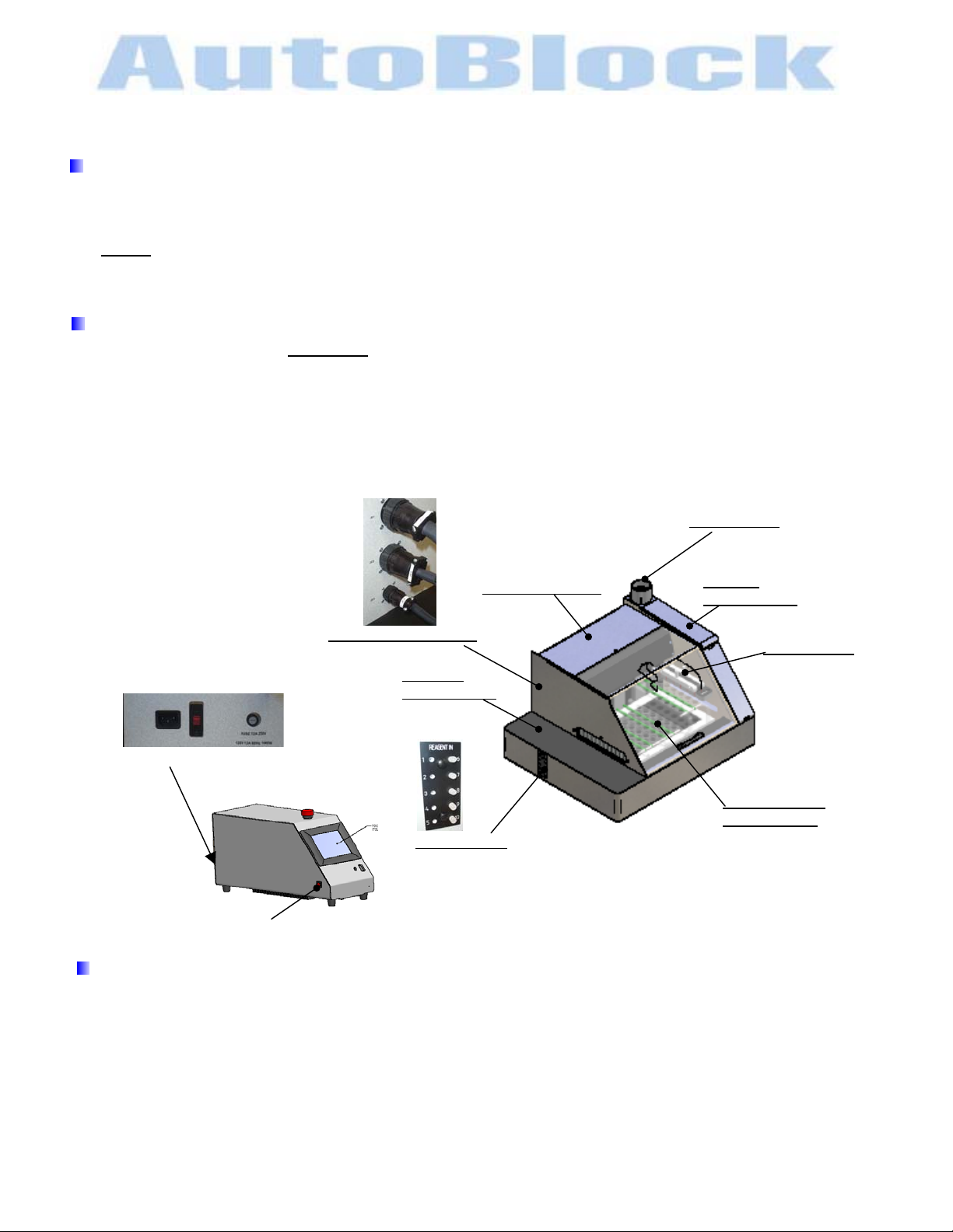
JC1
JC2
JC3
Lift Compartment
Exhaust vent
Exhaust
Compartment
electrical connections
Pumping
Compartment
Injection Arm
Power module/ Voltage / Fuse
Graphite Block
reagent ports
Compartment
ABP164
ff switch
Ventilation
The AutoBlock exhaust is located on the top right portion of the unit. Install a 4” diameter acid-resistant
duct and clamp to the exhaust outlet. Vent using state & federal guidelines. When connecting ductwork,
verify zero to negative pressure to prevent backflow. The length of the duct should not exceed 25’. Vent
the duct to the outside of the laboratory building or plumb into the existing ductwork.
ENVIRONMENTAL EXPRESS
For technical support call 1-800-745-8218 or send email to INFO@ENVEXP.COM
5528INSTALL rev 3 5 9/15/09
Page 6
INSTALLATION
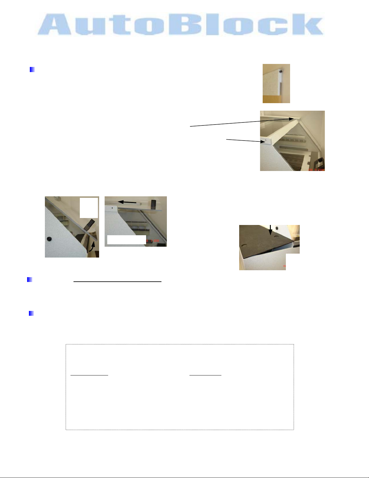
Front Door Installation
Unpack the front door assembly using caution not to scratch the acrylic.
Both hinge pins have been inserted into the door assembly
Remove the hinge pin from the left side using a hex wrench.
Place door in cabinet opening,
sliding the right side hinge pin into the cabinet location.
Align the left side hinge pin location & screw in the second hinge pin.
Hand tighten the hinge pin.
Lift the door & close it. It will be a snug fit. Lift the door up & slide back.
After the installation of the front door, Environmental Express does not warranty
breakage due to operator handling.
as shown.
Closing the
Insert edge first along the outside of the cabinet. Tilt the other edge at 10
the cabinet. Push down to close.
lift
door
up
slide door back
Pump Compartment Door
push down
on this edge
angle
pump compartment
door as shown
0
angle along the filter side of
Install Reagent Line
The following steps will connect 2.5 liter or standard 38mm top, reagent bottles to AutoBlock. These are
standard 2.5L acid bottles. For the DI water ports, 1 & 6, use a clean acid bottle filled with H
SINGLE UNIT DUAL UNIT
5 Flangeless Nuts 10 Flangeless Nuts
5 + 2 extra Flangeless Ferrules 10 + 2 extra Flangeless Ferrules
25’ Reagent Lines 1/16”ID 50’ Reagent Lines 1/16”ID
Vented Reagent Caps (optional)
Reagent Bottom of the Bottle Filter (optional)
Uptake Reagent Components
Components are supplied in a start up kit
2
O.
ENVIRONMENTAL EXPRESS
For technical support call 1-800-745-8218 or send email to INFO@ENVEXP.COM
5528INSTALL rev 3 6 9/15/09
Page 7
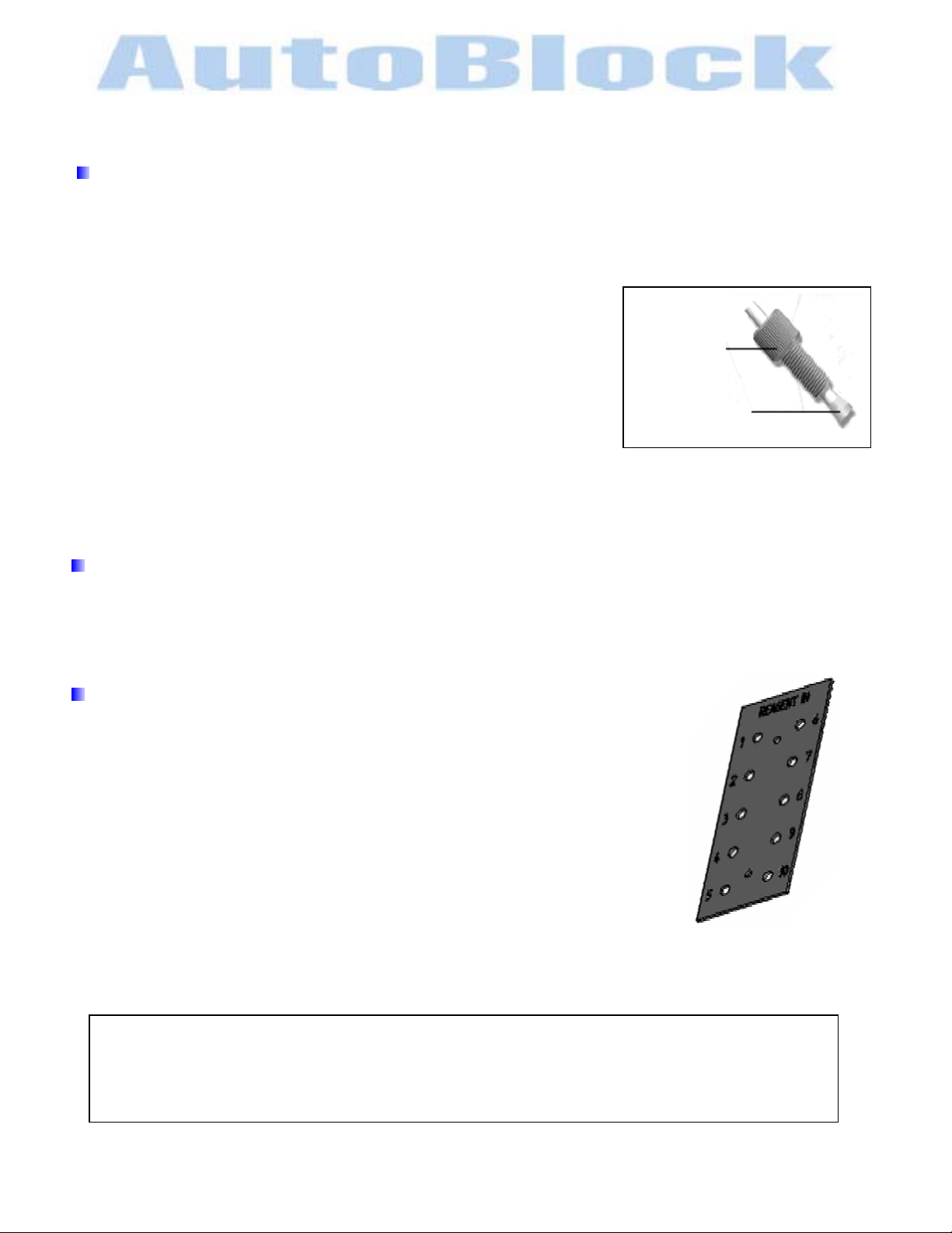
Reagent Line Assembly
1. Cut appropriate lengths of 1/16”ID Teflon tubing, not to exceed 5’ lengths. The ends need to be a
square-cut face.
2. Slide the flangeless nut over the tubing, with the nut threads facing the tubing end.
3. Slide the flangeless ferrule over the tubing, with the tapered portion of
the ferrule facing towards the nut. The large diameter of the ferrule
should be pushed to the end of the tubing.
4. AutoBlock reagent ports are located on the left side of AutoBlock
labeled #’s 1-10.
5. Insert the tubing with the flangeless ferrule into the receiving port
until it bottoms. While holding the tubing, tighten the Flangeless nut
finger tight. The tubing should not be able to move in the port.
Repeat for all ports available.
INSTALLATION
Flangeless nut
Flangeless Ferrule
reference diagram for placement
Placement of Reagent Rack
Position the six-bottle reagent rack (optional) on the left side of AutoBlock.
For dual systems, there may be two six-bottle reagent racks (optional).
AutoBlock Reagent Port
AutoBlock reagent ports are located on the left side of AutoBlock, labeled #’s 1-10.
The reagents have been set up in the following manner:
Single System Dual System**
If these reagents do not suit your application, you may change them. Changing the reagents and ports
numbers are addressed in the SERVICE TAB – SETUP REAGENT section.
*Port #1 H20(1) *Port #6 H20(6)
Port #2 HNO3(2) Port #7 KMnO4(7)
Port #3 HCL(3) Port #8 PERSULF(8)
Port #4 H2O2(4) Port #9 NH2OH(9)
Port #5 H2SO4(5) Port #10 H20(10)
*Ports #1 & #6 must remain H
**In a single system ports #6-10 have been plugged.
0
2
reagent plate
Vented Reagent Caps and Bottom of the Bottle Filter (optional)
Loosen the nut on the top of a vented reagent cap. Insert one end of reagent tubing through the nut until
it reaches the bottom of the 2.5L bottle. Hand tighten the nut.
A bottom of the bottle filter may be used to filer the reagent. Attach this to the end of the tubing before
inserting it into the 2.5L bottle.
ENVIRONMENTAL EXPRESS
For technical support call 1-800-745-8218 or send email to INFO@ENVEXP.COM
5528INSTALL rev 3 7 9/15/09
Page 8
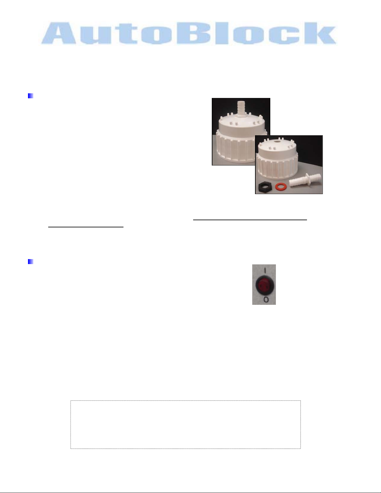
Install Drain Line & Carboy
• Remove the ½” barb fitting from the
bag of parts supplied
• Remove the nut from the fitting
• Remove the cap from the carboy
• Place the fitting into the cap. The treaded portion
of the fitting needs to be on the inside of the cap.
• Place the washer & then nut onto the fitting & tighten.
• Place the cap back onto the carboy.
• The drain line is located on the right side towards the back of the unit. Place the supplied ½” tubing
onto the barb fitting and the other end to the carboy.
direction the entire length.
The system is designed for downward gravity flow throughout the entire length to the carboy.
Place the carboy under the AutoBlock.
Electrical Box Installation
• Position the on/off switch to the off position.
• A 10’ power cord has been supplied.
Power requirements are standard 115VAC 12A US and Canada
Power requirements are standard 220VAC 6A International
Plug the power cord into the power module located in the back of the electrical box and into a
standard AC outlet
• Place the electronic box on the platform of the AutoBlock, left hand side of the unit. The mounting feet
will rest in the recessed holes.
• Connect the three cables from the electrical box to the AutoBlock system on the left side. JC1, JC2
and JC3 have been marked on the cable connector & on the AutoBlock.
INSTALLATION
carboy cap & bulkhead fitting
Insure the tubing goes in a DOWNWARD
ON
OFF
on/off switch
Congratulations
You have finished physically setting up the AutoBlock and are ready to move
onto a systems check and calibration. A systems check and calibration set up
must be done before any methods run.
ENVIRONMENTAL EXPRESS
For technical support call 1-800-745-8218 or send email to INFO@ENVEXP.COM
5528INSTALL rev 3 8 9/15/09
Page 9
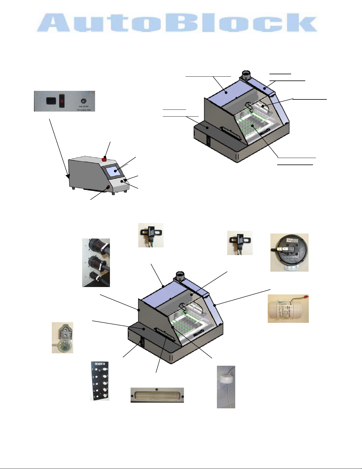
System Overview
g
y
on/o
(3)
9
Component Layout
Power module/ Voltage / Fuse
Emer
ABP164
ff switch
ency Stop Assembl
Touch Screen
USB
Stylus
Pumping
Compartment
Lift Compartment
Exhaust
Compartment
Injection Arm
Graphite Block
Compartment
JC1
JC2
JC3
electrical connections
ABP125
lift sensors
ABP125
Inj arm sensor
ABP152
pressure sensor
ABP127
leak detector sensor
ABP128
exhaust fan assembly
reagent ports
ABP151
HEPA filter
RTD -Sample Assembly
ABP130
ENVIRONMENTAL EXPRESS
For technical support call 1-800-745-8218 or send email to INFO@ENVEXP.COM
5528OVERVIEW rev3 9 9/10/0
Page 10
y
g
p
System Overview
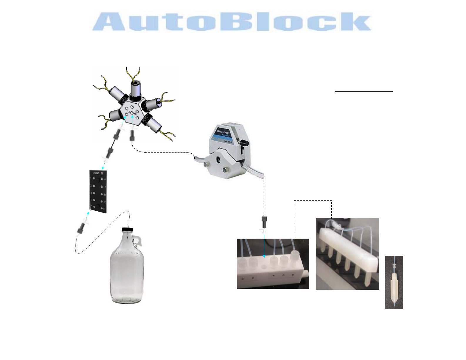
Reagent Flow Path
ABP122
5-Valve Assembl
Reagent-Valve
Tubing Kit -single
Reagent Ports/Cabinet
Teflon Tubin
ABP140
Uptake
1/8” Flangeless Nut
1/8” Flangeless Ferrule
for
General Cleaning
Wipe clean with mild cleaner or isopropyl.
ABP154
Pum
Head
Keep debris from inside of graphite block
wells.
ABP143
ABP144
Pump Tubing Kit
1/16” Flangeless Nut
1/16” Flangeless Ferrule
ABP108
Manifold
ottleReagent B
W/Plug
Sample Injection Kit
Injection arm with splitter
ABP159
Injection Guide
ENVIRONMENTAL EXPRESS
For technical support call 1-800-745-8218 or send email to INFO@ENVEXP.COM
5528OVERVIEW rev 3 10 9/10/09
Page 11
TOUCH SCREEN CONTROLLER
The touch screen controller is specifically designed for use with the AutoBlock. Once the system is
turned on, the AutoBlock software will automatically load. Pressing the screen tabs or input boxes with
the attached stylus activates the touch screen. It is not necessary to push very hard, this may damage
the screen.
Main Screen Functions
There are several operations that appear permanently on the touch screen.
There are FIVE tabs of operation located at the top of the touch screen:
The MANUAL screen will appear at start up.
-A pop up message will appear: “READY TO HOME MOTORS?” Press the Continue button.
-Motors will activate to initialize in their home positioning.
-A pop up message will appear: “MOTORS ARE HOMED” Press the Continue button.
To switch between tabs, press the appropriate tab with the stylus. Each tab will be described in this
manual to allow the analysts to fully operate the AutoBlock.
The main screen will go into sleep mode when left unattended. Touch the top of the screen with the
stylus to awaken.
Sensor Indicators
Alarm sensors are located in the upper left portion of the screen and when triggered change color. These
sensors may take a few moments to change its status, it is not instantaneous.
P
Located in the Exhaust Compartm ent. Detection if a pressure drop has occurred.
Green light will indicate a positive operating state
Red light will indicate the sensor has been activated & needs attention.
L
Located in the Pumping Compartment. It will detect if there is a leak present.
Green light will indicate a positive operating state
Red light will indicate the sensor has been activated, immediate attention should be given to this
MANUAL RUN PROGRAM SERVICE EXIT
Pressure Sensor
Leak Detector Sensor
situation. The AutoBlock will not operate until the leak has been resolved. Reference Start Up
Instructions–Sensor Validation section of this manual for addition information.
Manual Tab
ENVIRONMENTAL EXPRESS
For technical support call 1-800-745-8218 or send email to INFO@ENVEXP.COM
5528TOUCHCREEN Rev 2 11 9/10/09
Page 12

TOUCH SCREEN CONTROLLER
ABORT
If you need an emergency stop depress the
Activate the ABORT
By selecting the abort button, the abort operation will seize all communications to the control board.
The temperature will not read correctly and will not heat. All motion is stopped. The ABORT button will turn
green.
-A pop up message will appear: “DO YOU WANT TO ABORT”
Pressing the Cancel button will bring you back to the main screen and the abort command will not be activate.
Press the Abort button to activate the abort command, a pop up message will appear
“CONTINUE TO TURN ON FAN”
“CANCEL TO TURN OFF FAN”
Press the Continue button to turn the fan on.
If fumes are present or the block is greater than 40
Pressing the Cancel button to leave fan off.
Deactivate the ABORT
After selecting to turn on the fan or leave off
-A pop up message will appear: “READY TO HOME MOTORS?”, Press the Continue button.
-Motors will activate to initialize in their home positioning.
-A pop up message will appear: “MOTORS ARE HOMED”. Press the Continue button.
The ABORT command will then be deactivated and the ABORT button will turn red.
Abort Button
E-STOP immediately.
0
C, it is recommended to keep the fan on
Emergency Stop
Temperature Readouts
Actual temperature readings for samples & block are displayed in the upper right portion of the screen.
SX
G
Sample Temperature
Place the external thermocouple, located inside the front compartment, into a sample for accurate reading.
Temperature that has been set to the graphite block ,
Displayed in the upper left portion of the screen.
Reference the Manual Tab for setting the block temperature.
Manual Tab
Graphite Block Temperature, 0C
Sample Temperature, 0C
0
C
Manual Tab
ENVIRONMENTAL EXPRESS
For technical support call 1-800-745-8218 or send email to INFO@ENVEXP.COM
5528TOUCHCREEN Rev 2 12 9/10/09
Page 13

On Board Keyboard
To activate this feature, select the icon on the task bar with the stylus.
Typing
-keyboard acts as any standard keyboard
-press the SHIFT button to change the top row symbols/numbers
-press the CAPS button to change from low/capital letters
Move keyboard
- Touch the keyboard and drag across the screen to new location.
To deactivate the keyboards,
- select the icon on the task bar
- or the icon on the keyboard located on the bottom row next to the control button
- or the X in the upper right-hand corner
ENVIRONMENTAL EXPRESS
For technical support call 1-800-745-8218 or send email to INFO@ENVEXP.COM
5528TOUCHCREEN Rev 2 13 9/10/09
Page 14

START UP INSTRUCTIONS
These start up instructions are to aid in optimizing the performance of AutoBlock. You system has gone
through a quality control check during manufacturing. These parameters need to be checked at setup to
ensure the system is in operable condition and the parameters meet your laboratory specificat ions. All
parameters can be changed to meet your laboratory specifications.
If you need assistance during this set up instructions, please feel free to call Environmental Express
during normal business hours. Contact information is listed at the bottom of each page.
ON
Power switch & load software
The touch screen controller is specifically designed for use with the AutoBlock.
Once the system is turned on, WindowsXP will start up and the AutoBlock software will start to load.
This will take about 30-seconds
It is not necessary to push very hard, this may damage the screen.
Pressing the screen tabs or input boxes with the attached stylus activates the touch screen.
One the screen has initialized the onboard keyboard with pop up.
Disable the keyboard by depressing the DISABLE button located next to the control button
There are several options to start the AutoBlock software:
-Double Click the ABIII icon on the main Desktop
-Select the START button on the task bar and select the ABIII icon
-Select the START button on the task bar and select All Programs and then select the ABIII icon
The MANUAL screen will appear at start up.
-A pop up message will appear: “READY TO HOME MOTORS?” Press the Continue button.
-Motors will activate to initialize in their home positioning.
-A pop up message will appear: “MOTORS ARE HOMED.” Press the Continue button.
There are FIVE tabs of operation located at the top of the touch screen:
MANUAL RUN PROGRAM SERVICE EXIT
on/off switch
OFF
Testing Injection System
In Manual tab, prime the line with H
For initial injection test, H
1. Remove the pumping compartment cover, placing the electrical box off to the side of the AutoBlock unit.
2. Place 3-racks with vessels onto the lift arm.
The racks should be in the up position. Press the in the ALL button in the yellow section of the screen.
3. Inject each reagent line with 10ml of H2O. Inspect tubing for any air bubbles.
Refer to MANUAL TAB on instructions for injection
If air bubbles are present, inspect all connections & repeat by injecting 10ml of reagent for re-inspection.
Air bubbles may be caused from improper face-to-face connections.
4. Repeat for each port #1-5 (single unit) and #1-10 (dual unit)
O should be used on all ports.
2
O as follows.
2
Manual Tab
ENVIRONMENTAL EXPRESS
For technical support call 1-800-745-8218 or send email to INFO@ENVEXP.COM
5528STARTUP rev 3 14 9/10/09
Page 15

START UP INSTRUCTIONS
Sample Injection Tubing / Pump Calibration
Follow the steps to Calibrate Sample Injection Tubing and Calibrate Pump under the Service Tab in this
manual.
The Sample Injection Tubing and Pump(s) has been tested and calibrated during manufacturing.
It is best to calibrate the system again to ensure accuracy.
Maintenance
Review and set up the Maintenance portion under the Service Tab in this manual.
The maintenance schedule has been set during manufacturing. There will be popup alerts on the touch
screen to remind the operator to inspect & maintain the AutoBlock.
Sensor Validation
Change of status may take a few moments. It is not an instant response.
If these sensors indicators do not change status please review the System Overview section of this
manual for setting them to a positive operating condition.
1. From the Manual Mode, turn the fan on by pressing the FAN button.
The Pressure Sensor indicator
front door must be closed.
2. Close the front door and the pressure sensor indicator
3. Press the FAN button to turn the fan off. The pressure sensor indicator
The Leak Detector Sensor indicator
P
on the touch screen, will turn green when operating correctly. The
P
will turn red
P
will turn red.
L
on the touch screen will be green when no leak is detected.
Manual Tab
You are now ready to successfully run digestion methods in your new AutoBlock.
Reference Program Tab for creating and editing methods.
ENVIRONMENTAL EXPRESS
For technical support call 1-800-745-8218 or send email to INFO@ENVEXP.COM
5528STARTUP rev 3 15 9/10/09
Page 16

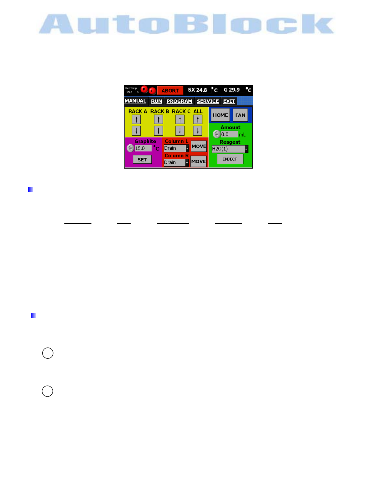
MANUAL TAB
The manual mode is just what it implies. In this mode, digestion functions (raising/lowering racks,
heating, cooling, injection, etc…) are performed individually by the analyst. The manual tab is used in
method development, troubleshooting and on going inspections, and other situations where hands-on
control of operations are required.
Manual tab screen with dual system
Rack Movement
The (3) 18-position rack have been designed to hold 50ml vessels for a 54-well block.
Each rack can be moved up or down individual from one another.
By pressing the will raise the rack will lower the rack
Rack A
Rack B
Rack C
All
After selecting
-A pop up message will appear: “RACK UP?”, Press Continue or Cancel button.
Cancel
A pop up message will appear: “CANCELLED?”, Press Continue button
You have canceled the command & return to the manual tab
Continue
The selected rack will move in the selected direction
A pop up message will appear: “RACK IS UP.”, Press Continue button
located on the left, columns 1-2-3
center location, columns 4-5-6
located on the right, columns 7-8-9
will raise or lower all three racks one at a time
(yellow section)
COLUMN & RACK DESIGNATION
or
ENVIRONMENTAL EXPRESS
For technical support call 1-800-745-8218 or send email to INFO@ENVEXP.COM
5528MANUAL rev3 16 9/10/09
Page 17

HOME
This operation will home the three lift motors and the injection arm motor.
The three lift motors will go to the down position and the injection arm will position itself over the drain.
Press the Home button
-A pop up message will appear: “HOME MOTOR?” Press Continue or Cancel button.
Cancel
You have canceled the command & return to the manual tab
Continue
The lift &injection arm motors will activate
A pop up message will appear: “RACKS ARE DOWN AND ARM IS LOCATED OVER THE
FAN
By pressing this button the fan will turn on or off.
A confirmation message fan is on/off. Press the OK button.
The fan will automatically turn on when the block is over 40
Graphite
Set the temperature to the graphite block with the or
The temperature is set in
After selecting a temperature press the
- A pop up message will appear: “THE BLOCK TEMPERATURE HAS BE SET” Press Continue button
The change will also reflect the readout on the upper right corner of the screen
NOTE:
The temperature of the graphite block will not be the temperature of the external thermocouple (sample
probe).
Test the sample temperature to achieve proper graphite temperature.
Heat the graphite block to 115
The use of the reflux cap (SC506) will raise the sample temperature 10
(blue section)
DRAIN.”, Press Continue button
(blue section)
(pink section) Range: 150C-1500C
0
C, inc/dec by 0.10C
MANUAL TAB
0
C, and cannot be turned off below 400C
buttons, or by using the keyboard.
SET
button.
0
C, the sample probe should read 950C
0
C
ENVIRONMENTAL EXPRESS
For technical support call 1-800-745-8218 or send email to INFO@ENVEXP.COM
5528MANUAL rev3 17 9/10/09
Page 18

p
MANUALTAB
Arm
Select which column you would like a reagent injected to by the pull down menu
-Select DRAIN, 9,8,7,….1
-Press the MOVE button
-A pop up message will appear: “MOVE INJECTION ARM?”,
Press Continue or Cancel button.
Cancel
You have canceled the command & return to the manual tab
Continue
The injection arm will move to the selected column
A pop up message will appear: “INJECTION ARM MOVE COMPLETE.”
Press Continue button
NOTE:
There will be a left & a right splitter.
ARM (1-5) will inject thru the left splitter
ARM (6-10) will inject thru the right splitter
(red section)
**Dual System**
single unit system shown
dual unit has two s
litters
Inject
Select which column to be injected thru the ARM-section and move injection arm before proceeding.
The Inject command does not automatically purge or prep. Bring the injection arm to he drain and inject
6ml H20(1) to purge and 6ml of reagent to prep.
Amount
Select the amount of reagent to be injected with the
The volume is set in ml. inc/dec by 0.1ml
Reagent
Select the Reagent to be injected from the drop-down menu. Reagents have been pre-installed.
Reference the SERVICE TAB-REAGENT SETUP for port configuration and to make changes
EXAMPLE: H20(1) Reagent H20 is connected to port (1) on the AutoBlock unit
-Select REAGENT(PORT)
After selecting a reagent press the
-A pop up message will appear: “INJECT REAGENT?” Press Continue or Cancel button.
Cancel
You have canceled the command & return to the manual tab
Continue
The reagent will inject the specified amount
A pop up message will appear: “REAGENT INJECTED.” Press Continue button
NOTE:
REAGENTS (1-5) will inject thru the left splitter
REAGENTS (6-10) will inject thru the right splitter
(green section) Range: 0.1ml-50.0ml
INJECT
**Dual System**
button
or buttons or by using the keyboard.
ENVIRONMENTAL EXPRESS
For technical support call 1-800-745-8218 or send email to INFO@ENVEXP.COM
5528MANUAL rev3 18 9/10/09
Page 19

RUN TAB
The RUN TAB determines what methods will be selected and to what racks/columns they will be run.
Rack A / Rack B / Rack C
After determining which rack(s) are going to be used, select the method you want to run.
Some methods have been pre-programmed. Reference Program tab in the manual for adding/editing
methods
Load racks onto the lift arms in the down position
NOTE:
For proper airflow, all racks should be filled with empty cups. No need to run reagents in those columns.
Each column must contain 6 cups. Polypropylene cups can only be used to 130
Selecting Methods
A default program will appear in all three racks. Select method to be used from the pull down menu.
When selecting a method start with
Protocol for running different methods at the same time
The same temperature and the same reagents must be used for each method.
This will allow you to run 1, 2 or 3 different methods at once.
Activating Selecting Columns
If running all three racks, select column 9
If running racks A & B, select column 6
If running Rack A only, select column 3
-A pop up message will appear: “COLUMNS X-X ARE ACTIVE.” Press Continue button.
the active column indicator will turn green
Deactivating Selecting Columns
Select the column to deactivate
The de-active column indicator will turn black
Run Methods
Press the RUN METHODS button to begin.
The AutoBlock software will check for syntax errors in methods before starting
-A pop up message will appear: “CONTINUE WITH METHOD?”, Press Continue or Cancel button.
Cancel
A pop up message will appear: “METHODS CANCELED?”, Press Continue button
You have canceled the command & return to the run tab
Rack A. then proceed to Rack B then Rack C.
Run Tab
0
C
ENVIRONMENTAL EXPRESS
For technical support call 1-800-745-8218 or send email to INFO@ENVEXP.COM
5528RUN rev 3 19 9/10/09
Page 20

RUN TAB
Run Methods continued
Continue
The racks and the injection arm will home and the method will begin.
If syntax terror occurs
The AutoBlock software will check for syntax errors in methods before starting
-A pop up message will appear: “SYNTAX ERROR XX –method command line appears”
-Look up syntax error in the PROGRAM TAB section of this manual.
-Press Continue button
-A pop up message will appear: “SYNTAX ERROR. METHOD CANNOT START. PLEASE FIX ERRORS.”
- Press Continue button
-Return to the PROGRAM TAB to edit the method. Saving the edited method before running.
If incompatible methods occurs
The AutoBlock software will check for syntax errors in methods before starting
-A pop up message will appear: “HEAT TEPERATURES MUST BE TH SAME FOR ALL THREE METHODS”
-Press Continue button
-A pop up message will appear: “SYNTAX ERROR. METHOD CANNOT START. PLEASE FIX ERRORS.”
-Press Continue button
-Select compatible methods to run or run at different times
Under the rack/method/column section, the screen will show which current command is being executed
in the method.
Pause Button
You may select this at any point. AutoBlock will finish the current step and then pause.
-A pop up message will appear: “METHODS WILL PAUSE AS SOON AS CURRENT COMMAND IS
COMPLETE” Press Continue button.
Continue
The method will now resume from it’s last executed command.
Main Screen Abort Button
You may select this at any point. By selecting the abort button the abort operation will seize all
communications to the control board. The temperature will not read correctly and will not heat.
All motion is stopped. Reference TOUCH SCREEN CONTOLLER section of this manual
If you need an emergency stop depress the E-STOP.
5528RUN rev 3 20 9/10/09
A pop up message will appear: “METHODS PAUSED. TO RESUME METHODS CLICK
CONTINUE ?”, Press Continue button
ENVIRONMENTAL EXPRESS
For technical support call 1-800-745-8218 or send email to INFO@ENVEXP.COM
Page 21

PROGRAM TAB
g
Methods are stored and can be edited. Custom methods can be programmed into the AutoBlock.
Below depicts the Program Tab. Each command will be described in detail to ensure operator
understandin
.
program mode –heat screen
HEAT
Set the block temperature in 0C. Range: 150C to 1500C
This is not
Polypropylene cups can only be used to 130
Command Sequence:
1. Select HEAT command from the main menu
2. Select the block temperature by up or down buttons or by keyboard. (
3. Added User Notes. With the keyboard activated, press comment area with stylus and type
example note: heat samples for 2 hours
NOTE: Racks will not lower into graphite until within 5 degrees of set point.
sample temperature.
Program Tab
0
C
0
C)
INJECT
This command adds reagents. Range: 0.1 - 50 ml
The injection arm will move over the drain, raise the racks, prep the lines with
6ml of reagent, inject the specified amount of reagent into selected columns,
move the injection arm to the drain & purge lines with 6ml of water. Racks are
left in the up position.
The lines will prep & purge unless specified by the no prep or no purge command. This can be done by
using the ADD command.
If the reagent is not listed in the drop down menu, go to the SERVICE TAB –Setup Reagents,
to add them in.
Command Sequence:
1. Select INJECT command from the main menu
2. Select the reagent from the drop down menu
3. Select amount to inject by arrow buttons or by keyboard (ml)
4. Added User Notes. With the keyboard activated, press comment area with stylus and type.
Proceed to the continue button
program mode –inject screen
ENVIRONMENTAL EXPRESS
For technical support call 1-800-745-8218 or send email to INFO@ENVEXP.COM
5528MANUAL-program Rev 3 21 9/15/09
Page 22

PROGRAM TAB
WAIT
Sets the amount of time the samples will be heated during a step.
Range: 1-999 minutes.
The method will wait for the set graphite temperature to be reached,
0
C degrees, rack are then lowered. The method will then wait for the
±5
specified number of minutes.
Command Sequence:
1. Select WAIT command from the main menu
2. Select the wait time by up or down buttons or by keyboard. (minutes)
3. Added User Notes. With the keyboard activated, press comment area with stylus and type.
Proceed to the continue button
COOL
Set the amount of time the samples will be cooled. Range: 1-999 minutes
The racks will be raised out of the graphite block and cool for the specified
number of minutes. The fan will automatically increase to its maximum for
efficient sample cooling.
Command Sequence:
1. Select COOL command from the main menu
2. Select range by up or down buttons or by keyboard. (minutes)
3. Added User Notes. With the keyboard activated, press comment area with stylus and type.
Proceed to the continue button
program mode –wait screen
program mode –cool screen
PAUSE
An operator will receive a pop up message. The method will not execute
the next command until the analysts responds.
Command Sequence:
1. Select PAUSE command from the main menu
2. Add message with the keyboard activated, press comment area
Example message: Insure volume level is correct
Proceed to the continue button
DELETE
Directly deletes last command from the method screen.
Command Sequence:
Proceed to the continue button
with stylus and type.
1. Select PAUSE command from the main menu
ENVIRONMENTAL EXPRESS
For technical support call 1-800-745-8218 or send email to INFO@ENVEXP.COM
program mode –pause screen
program mode –sample program
5528MANUAL-program Rev 3 22 9/15/09
Page 23

EVERY METHOD
At the end of each method the following two commands need to be added
With the keyboard activated, press command area and type in the command string as follows:
Press the CONTINUE button and SAVE the method
enter: COLUMN DRAIN
enter: DISPENSE H2O(1) 10
PROGRAM TAB
OPEN
Opens directory where previous methods were saved MyComputer\LocalDisk(C)\HardDisk\Methods\
Select the OPEN button
Select a method from the directory
Press the OK button
SAVE
Save a new or edited method.
Select the Save button and activate keyboard
Type method name in FILE NAME area, Press OK button
Methods are stored in this directory MyComputer\LocalDisk(C)\HardDisk\Methods\
NEW
Clears the method command area enables operator to program command s to a new method
Select the NEW button
The methods field clears
EDIT
Allows the operator to modify current methods.
Method command area must have commands programmed on the screen
Select the EDIT button
Highlight the command to edit, activate the keyboard to make changes.
Cancel
You have canceled the command & return to the main PROGRAM TAB
Continue
Saves the change and returns to the main PROGRAM TAB to continue programming
ENVIRONMENTAL EXPRESS
For technical support call 1-800-745-8218 or send email to INFO@ENVEXP.COM
5528MANUAL-program Rev 3 23 9/15/09
Page 24

IMPORT/EXPORT METHOD
Methods are stored in this directory MyComputer\LocalDisk(C)\HardDisk\Methods\
Methods are saved by METHOD NAME.TXT file example: 200.7 WATERS 50ML.TXT
Methods can also be written using notepad or word. Save as a text file (.txt) onto a USB stick
Basic operator knowledge of Microsoft Windows is required
Insert USB stick into USB slot near the touch screen
IMPORT
There are two ways to import methods
1. From the PROGRAM TAB, press OPEN button
Select MY COMPUTER from the side icons
Select TRAVELDRIVE (D:) and press the OPEN button
Select METHODS and press the OPEN button
Select method to import and press the OK button
Save the method using the SAVE procedures on the previous page
2. Press the START tab on the task bar
Select MY COMPUTER from the side icons
Select TRAVELDRIVE (D:) and press the OPEN button
Select method
Using the EDIT, COPY TO FOLDER
Select MyComputer\LocalDisk(C)\HardDisk\Methods, press the COPY button
EXPORT
There are two ways to export methods
1. From the PROGRAM TAB, open the method to be exported
press SAVE button
Select MY COMPUTER from the side icons
Select TRAVELDRIVE (D:) and press the OPEN button
Activate the keyboard, type method name in FILE NAME area
Press OK button
2. Press the START tab on the task bar
Select MY COMPUTER from the side icons
Double click LOCAL DISK(C:)
Double click HARDDISK
Double click METHODS
Select method to export
Using the EDIT, COPY TO FOLDER
Select TRAVELDRIVE (D:), press the COPY button
PROGRAM TAB
EXPORT LOG
Logs are stored in this directory MyComputer\LocalDisk(C)\HardDisk\Data\
Using the same procedure for Exporting Methods extracting method logs from the DATa directory.
Data logs are saved by MethodName.TXT Hour_Minute Month_Day_Year. DAT file
example: 200.7 WATERS 50ML.TXT12_30_FEB_01_09.DAT
ENVIRONMENTAL EXPRESS
For technical support call 1-800-745-8218 or send email to INFO@ENVEXP.COM
5528MANUAL-program Rev 3 24 9/15/09
Page 25

SYNTAX ERRORS
Run Tab
Select the method(s) and columns to run
Press RUN METHODS button
If there is an error in the method programming a popup will appear, note what syntax occurs
syntax error will appear with the following format:
SYNTAX ERROR# -COMMAND
The method will not continue until the syntax error is fixed in the program.
Return to the Program Tab, open the method and edit. SAVE the method before returning to the Run Tab
# definition and description
10 value out of range
20 unrecognized command
30 reagent not recognized
40 loop must execute at least 1 time
50 loop must use a stop loop command
60 elevator command must use up or down to specify location
PROGRAM TAB
ENVIRONMENTAL EXPRESS
For technical support call 1-800-745-8218 or send email to INFO@ENVEXP.COM
5528MANUAL-program Rev 3 25 9/15/09
Page 26

SERVICE TAB
The SERVICE TAB is set up for AutoBlock to be calibrated,
maintained, and custom levels set for optimal performance.
service tab screen
Setup Reagents
Select SETUP REAGENTS button from the SERVICE TAB
Reagents are set to correspond with reagent ports. AutoBlock reagent ports are located on the
left side of AutoBlock, labeled #’s 1-10. The reagents have been set up in the following manner:
Single System Dual System**
**In a single system ports #6-10 have been plugged.
If the reagent arrangement or if other reagents are used, you may change the list.
In the following steps. Listed below are common reagents with viscosity ratings.
Reagent
H2O(1) (ports 1 & 6, cannot be changed) Low
HNO3(2) Nitric Acid Medium
HCL(3) Hydrochloric Acid Low
H2O2(4) Hydrogen Peroxide 30% Medium
H2SO4(5) Sulfuric Acid High
H2O(6) (ports 1 & 6, cannot be changed) Low
KMnO4(7) Potassium Permanganate Low
PERSUL(8) per sulfates Low
NH2OH(9) Hydroxylamine Low
H2O(10) Water Low
Viscosity ratings control the pump speed to maximize efficiency and provide volume delivery accuracy.
Low Viscosity, fast pump speed, (reagent near the viscosity of water)
High Viscosity, slow pump speed
*Port #1 H20(1) *Port #6 H20(6)
Port #2 HNO3(2) Port #7 KMnO4(7)
Port #3 HCL(3) Port #8 PERSUL(8)
Port #4 H2O2(4) Port #9 NH2OH(9)
Port #5 H2SO4(5) Port #10 H20(10)
*Ports #1 & #6 must remain H
O
2
Viscosity
ENVIRONMENTAL EXPRESS
For technical support call 1-800-745-8218 or send email to INFO@ENVEXP.COM
5588SERVICE rev4 26 9/15/09
Page 27

A
t
SERVICE TAB
reagent setup screen reagent new screen
Setup Reagents
•
Selecting a different reagent on a port:
fter selecting SETUP REAGENTS button from the SERVICE TAB use the pull down menu on the p
by pressing the arrow button.
-Select the reagent from the list.
• To add a reagent to the pull down menu, you are able to add your own.
Select the New button from the screen. A new screen will appear, input information needed.
Reagent
With the keyboard activated, press reagent area and type in Reagent Name(port#)
No spaces allowed
Example: HCL(3) Reagent Name:HCL used on Port #3
Viscosity
Select the pull down menu by pressing the arrow button, choose Low, Medium, High.
SAVE the input information.
-A pop up message will appear: “NEW REAGENT ADDED.” Press Continue
-Select RETURN TO SETUP PORTS button to return to the setup screen
• To deleted a reagent on the pull down menu.
Select the DEL button from the screen. A new screen will appear, input information needed.
Reagent
Select Reagent to be Deleted from the pull down menu by pressing the arrow button
Choose Reagent Name, the viscosity associated with the reagent will appear in the Viscosity
of Reagent box
DELETE the reagent information
-A pop up message will appear: “REAGENT DELETED.” Press Continue
-Select RETURN TO SETUP PORTS button to return to the setup screen
• To change a reagent information on the pull down menu. (name change or viscosity rate)
You will need to add a new reagent & delete the old reagent
Select Main Menu button to return to the SERVICE TAB. By selecting the Main Menu button, the new port
selection has been saved.
continued
or
ENVIRONMENTAL EXPRESS
For technical support call 1-800-745-8218 or send email to INFO@ENVEXP.COM
5588SERVICE rev4 27 9/15/09
Page 28

Calibrate Temp
The Graphite Block has been tested and calibrated during manufacturing to ensure
0
a +/-2
The graphite block temperature needs calibration if a large variation is noted.
Consult Environmental Express before calibrating.
After selecting the Calibrate Temp button
-A pop up message will appear:
“DO YOU WANT TO CALIBRATE THE GRAPHITE BLOCK? YOUR OLD CALIBRATION TEMPERATUE
WILL BE LOST.” Press Continue or Cancel button.
Cancel
You have canceled the command & return to the Calibration screen
Your current calibration temperature will show in the actual temperature box
Continue
• After the graphite Block temperature reaches 90
• Record the actual graphite block temperature with an infrared thermometer.
• Enter the
using the keyboard. (
• SAVE the input information.
Select
C variation in temperature range.
-A pop up message will appear: “THE BLOCK IS BEING SET TO 90
TEMPERATURE HAS STABILIZED, RECORD ACTUAL TEMPERATURE READING”
or by
Main Menu button to continue back to the SERVICE TAB screen.
G
readout in the Graphite Block Actual Temp. This may be done with the UP or DOWN buttons
O
C)
SERVICE TAB
0
C, let the temperature stabilize for 15 minutes.
0
C. WAIT 15MIN AFTER
calibrate temp screen
calibrate pump screen
Calibrate Pump
To
maintain an accurate injection volume and viscosity rating,
th
e pump requires calibration.
Co
ntact Environmental Express for an Excel worksheet to calibrate injection tubing.
Se t the initial length of tubing to 108”.
N ote:
Check all lines for air bubbles & clogs before calibrating
Ca
librate Injection Tubing
1.
Label each vessel 1-6. Weigh six dry, clean test tubes, record weight in chart.
2.
Place test tubes in order #1-6, from front to back into a rack.
In the MANUAL TAB, place in rack C position and raise the rack.
3. Prime the line with 6ml of H O.
INJECT field(green section)
Amount
Set the volume to 6ml, by changing the amount of reagent with the UP or DOWN
Reagent
Select the H2O(1) to be injected.
With injection arm over the drain, press the INJECT button
4. After the lines have been primed, Move the ARM(red section)
Set the position of the arm location over the test tubes, by selecting the correct column from the Column L
drop down menu
Press the MOVE button
5. Change the Amount of volume to 30ml (green section)
Press the INJECT button
2
buttons
manual tab screen
ENVIRONMENTAL EXPRESS
For technical support call 1-800-745-8218 or send email to INFO@ENVEXP.COM
5588SERVICE rev4 28 9/15/09
Page 29

SERVICE TAB
Calibrate Pump
6. After the reagent has injected 30ml.
After the lines have injected, Move the ARM(red section) over the drain, by selection from the Column
L drop down menu
Press the MOVE button
7. Re-weigh each test tube and record the total weight (tube +H
8. Average range is 2%
• When the average range reaches 0-2%, you are ready to calibrate the pump(s).
Reference SERVICE TAB section on pump calibration
• If the target range exceeds ±2%, refer to the Amount Trimmed column.
This is the amount of tubing that needs to be cut off to the corresponding row.
a. Pull the tubing from the nozzle.
b. Measure the amount to be cut, refer to the Amount Trimmed column
Cut each tubing with a tube cutter
8. Dry test tubes and repeat steps 3-5 until the target range reaches ±2%
9. Return to the Service Mode tab and select Calibration Pump button.
10. Under the heading, Pump1 actual ml injected, enter value by using the UP or DOWN buttons
or by using the keyboard. (ml).
This value is obtained from the Calibrate Injection Tubing worksheet. Reference the min-max-middle
values. Use the MIDDLE value for the pump1 actual ml injected.
11. SAVE the input information.
Select Main Menu button to continue back to the SERVICE MODE screen. By selecting the Main Menu
button, the new calibration has been saved.
In a dual system, the second injection arm tubing is calibrated in the same manner, except using H
and Arm(6-10).
continued
2
O)
single unit system shown
dual unit has two splitters
O(6)
2
ENVIRONMENTAL EXPRESS
For technical support call 1-800-745-8218 or send email to INFO@ENVEXP.COM
5588SERVICE rev4 29 9/15/09
Page 30

SERVICE TAB
A
Maintenance
This section is designed to remind the operator when it is time for
replacement of parts or calibration of processes.
Failure to adhere to AutoBlock maintenance instructions and/or
requirements can void all warranties and result in damage to the
utoBlock, loss of samples and/or losses not covered by the
warranty. Please review the warranty section of this manual.
After selecting the MAINTENENCE button, there are several items to
be addressed on (3) pages. Next to each maintenance item shows:
date last serviced - service indicator - next service date
Maintenance items that need addressing are:
Graphite Calibration Teflon Tubing Pump 1 Teflon Tubing Pump 2
System Clean Pump Tubing 1 Pump Tubing 2
VICI Emitters Pump Calibration 1 Pump Calibration 2
HEPA Filter Check Waste Drum
After service has been completed double click the SERVICE button to update
the screen. This will change the button from red to green and change the service dates.
Select MAIN MENU button to continue back to the SERVICE TAB screen.
By selecting the Main Menu button, the new information has been saved
before continuing onto the next/previous page.
Options
AutoBlock comes with 2-pages of recommended
preset features. Recommended service days may be
changed by the operator to increase or decrease based
on usage and standard laboratory protocol.
Time entered is in days.
Options included:
By selecting the UP or DOWN button
each item will change its current value
Recommended service days have already been provided.
Automatic Reminders
System Clean 30
HEPA Filter 180
VICI Emitters 365
Graphite Calibration 365
Fan Speed 100%
Pump Tubing 365
Teflon Tubing 365
Pump Calibration 30
Waste Drum 30
Select MAIN MENU button to save data & continue back to the SERVICE TAB screen.
service (days)
365
365
100
manual screens
this third screen is only shown in a
options screen
dual system
ENVIRONMENTAL EXPRESS
For technical support call 1-800-745-8218 or send email to INFO@ENVEXP.COM
5588SERVICE rev4 30 9/15/09
Page 31

Supplies
Call Environmental Express for all your AutoBlock supplies. Have your AutoBlock serial number with you, this is
located in the back of the unit and inside the exhaust compartment.
After selecting the SUPPLIES button, Environmental Express contact information will appear.
ENVIRONMENTAL EXPRESS
490 Wando Park Blvd. Tel 800-343-5319
Mt. Pleasant, South Carolina 29464 Tel 843-881-6560
Fax 843-881-3964
Email INFO@EnvExp.Com
The current software version that is running on this AutoBlock unit will appear at the bottom of screen.
Press SPARE LIST button
A scroll down list of supplies will appear. There is also a supplies list in your manual.
SERVICE TAB
ENVIRONMENTAL EXPRESS
For technical support call 1-800-745-8218 or send email to INFO@ENVEXP.COM
5588SERVICE rev4 31 9/15/09
Page 32

Supplies
Call Environmental Express for all your AutoBlock supplies.
Have your
exhaust compartment.
ENVIRONMENTAL EXPRESS
490 Wando Park Blvd. Tel 800-343-5319 or
Mt. Pleasant, South Carolina 29464 Tel 843-881-6560
Fax 843-881-3964
Email INFO@ENVEXP.COM Email INFO@ENVEXP.COM
AutoBlock serial number with you; this is located in the back of the unit and inside the
P/N P/N DESCRIPTION DESCRIPTION QTY QTY
per package per package
ABP103
ABP104
ABP105
ABP106
ABP107
ABP108
ABP120 Pump Motor Assembly 1
ABP121 Heater Mat Assembly 1
ABP122 5-Valve Assembly 1
ABP123 Lift Motor Assembly 1
ABP124 Injection Arm Motor Assembly 1
ABP125 Photo Sensor Assembly 1
ABP127 Leak Detector Assembly 1
ABP128 Exhaust Fan Assembly 1
ABP129 RTD-Block Assembly 1
ABP130 RTD-Sample Assembly 1
ABP140 Reagent-Valve Tubing Kit (single) 1
ABP141 Reagent-Valve Tubing Kit (dual) 1
ABP143 Sample Injection Kit 1
ABP144 Pump Tubing Kit 1
ABP145 Insulation Kit, 9pc set 1
ABP149 10L Carboy w/Cap & Fitting 1
ABP150 Thumbs Screw 3
ABP151 HEPA Filter 1
ABP152 Pressure Sensor 1
ABP153 Drain Tubing Kit 1
ABP154 Pump Head 1
ABP159 Injection Guide 6
ABP163 54-well Rack, 18-position 3
ABP164 On/Off Switch 1
ABP171 Power Cord 1
VICI Emitter Disk 4
Pump to Motor Coupling set 2pc
Tygon Tubing for Waste Line 10’
Teflon Line for Uptake 25’
Replacement Solenoid 1
Manifold w/Plug 1
ENVIRONMENTAL EXPRESS
For technical support call 1-800-745-8218 or send email to INFO@ENVEXP.COM
5528SUPPLY rev3 32 9/10/09
Page 33

EXIT
Closes the program, shutting down the system and saving data
Select the blue EXIT button in the center of the screen
-A popup message will appear: “SAVING DATA BEFORE EXIT. THIS WILL TAKE A FEW MINUTES.”
-Select the Continue button.
When the AutoBlock software has finished exiting the top row of the screen will change
EXIT TAB
ENVIRONMENTAL EXPRESS
For technical support call 1-800-745-8218 or send email to INFO@ENVEXP.COM
5528EXIT rev 3 33 9/10/09
Page 34

Warranty
The Environmental Express AutoBlock is warranted to heat, hold temperature, automatically add
reagents, Warranty lift racks, cool samples with air flow and perform the stated functions of th e touch
screen controller for a period of ONE YEAR. This 1-year warranty is divided into two sections as follows:
90-Day Warranty
The 90-day warranty covers parts, shipping and labor for a period of ninety (90) days from the original
ship date, thereafter it expires. This warranty applies only in the case of damage or failure caused by
reasonable and normal laboratory use.
9-Month Warranty
The 9-month warranty begins immediately following the 90-day warranty. It covers parts and ground
shipping costs for the replacement parts only. This warranty applies only in the case of damage or failure
caused by reasonable and normal laboratory use. The 9-month warranty expires 365-days after the
original ship date.
Warranty Disclaimer
Environmental Express makes no other warranty, expressed or implied. Environmental Express shall not
be liable for consequential, incidental, specific or any other indirect damages resulting from economic
loss or property damages sustained by any customer from use of this product.
Environmental Express does not warrant the AutoBlock against damage resulting from chemical
reactions that may occur between reagents or between samples and reagents or between various liquids
and components of the AutoBlock. It is the responsibility of the laboratory to verify the compatibility of the
reagents, heat and time indexes, the compatibility of each sample matrix and other varying digestion
method conditions prior to operation.
Charges Not Covered by Warranty
• Failure to retain the original shipping crate and all other packaging materials for at least 90-days could
result in additional charges should repairs prove necessary.
• Failure to adhere to AutoBlock maintenance instructions and requirements can void all warranties and
result in damage to the AutoBlock, loss of samples, and create repair issues not covered by the
warranty. See maintenance section instructions.
How the Warranty Works
Upon receipt of the unit it is the laboratory’s responsibility to inventory all parts and immediately notify
Environmental Express of any suspected defects or missing parts. If during the first 90-days following the
original ship date the unit malfunctions, a telephone call to troubleshoot the issue must be initiated by the
laboratory. If it is deemed by the technical staff of Environmental Express that the problem cannot be
fixed by the lab, and that the failure occurred during normal and accepted laboratory operations, then a
written Return Authorization Form and Number will be issued by Environmental Express. The AutoBlock
will be returned to Environmental Express in its original shipping container.
For technical support call 1-800-745-8218 or send email to INFO@ENVEXP.COM
5528WARRANTY rev 3 34 9/10/09
ENVIRONMENTAL EXPRESS
Page 35

Repair
If your system requires attention beyond basic maintenance, please follow the guidelines below. Failu re
to so could result in loss of warranty protection and increased charges.
Repair Approval
Any attempt by laboratory personnel to repair the AutoBlock without first obtaining Environmental
Express’ written consent may void all or part of the Warranty, expressed or implied. Call 800-343-5319 or
(1-843-881-6560 outside the US) to obtain approval before beginning any repair work.
In-Lab Troubleshooting & Repairs
The AutoBlock has been engineered so that mechanically minded laboratory personnel can perform most
troubleshooting, repairs and tests. Technical assistance in such circumstances is always provided over
the phone (or via email, fax, etc…) by Environmental Express, whether the AutoBlock is in or out of the
warranty periods. There is no charge for this assistance. The AutoBlock is component based, making
most repairs quick.
Repair by Manufacturer
In the unlikely event that the unit must be returned to the manufacturer, it is the lab’s responsibility to:
Obtain a
1 Coordinate shipment and insurance with Environmental Express
2 Properly pack* the AutoBlock in approved materials only*
3 Place a Purchase Order with Environmental Express for repair
These elements are critical to a successful repair experience.
Return Authorization Form and Number
Return Packing & Shipping
It is the responsibility of the laboratory to retain in good condition the original crate and other packing
material for a period no less than 90-days following the receipt of the AutoBlock. If the original shipping
container is not available, a new shipping container must be purchase from Environmental Express prior
to shipment. Shipping charges and insurance from your lab to Environmental Express, and return
shipment charges via standard trucking line will be the responsibility of the lab except for approved 90day warranty claims.
Inspection upon Receipt
Upon receipt, Environmental Express will inspect, repair and return the unit in a timely manner, and bear
associated costs covered by warranty, if any applies. However, if it is determined by Environmental
Express that the damage to the AutoBlock was caused by negligence or improper use or improper
packaging/shipment, no warranty shall apply. In such case, reasonable and customary repair charges will
apply including freight and insurance cost to and from the laboratory.
Additional Information & Help
If you have any questions or concerns do not hesitate to pick up the phone and call 800-343-5319 or
(1-843-881-6560 outside the US). Standard hours of operation are 8:30am-5:30pm EST-Monday through
Friday excluding holidays. You can email questions to INFO@ENVEXP.COM at any point. Please include
you name, company name & telephone number. A technical service representative will respond as
quickly as possible. This manual addresses issues normally seen in the field.
ENVIRONMENTAL EXPRESS
For technical support call 1-800-745-8218 or send email to INFO@ENVEXP.COM
5528WARRANTY rev 3 35 9/10/09
 Loading...