

Page 1
Magnetic Field
Logger ML-1
user instructions
English
Postal address: EnviroMentorAB, Box 5124, SE-402 23 Göteborg, Sweden.
Address (visitors): Gamla Almedalsvägen 6, Göteborg. Tel: +46-31-703 44 30. Fax: +46-31-703 44 33.
E-mail: jorgen@enviromentor.se Home page: http://www.enviromentor.se
EnviroMentor has both the measuring
instruments and the expertise
EnviroMentor AB is a young, skills-based company, yet is also one of the
oldest in its field. All of our measuring instruments have been developed
in extremely close cooperation with researchers at Chalmers Institute of
Technology in Göteborg. EnviroMentor AB is wholly owned by Radians
Innova AB, a company which in turn is owned by two of Sweden’s most
powerful financial institutions. This combination of excellent skills and
good financial resources provides us with the potential to carry on continual
product development, keeping pace with the latest discoveries made by
researchers. You can find out all about our current range of measuring
instruments for the electrical environment from EnviroMentor’s various
product sheets. Please do not hesitate to contact us if you would like further
information. You can also visit our home page:
http://www.enviromentor.se
Karlssons Språkservice AB, Gothenburg, Sweden +46 31-704 52 50
Page 2
ML-1ML-1
2 © Enviromentor AB 1999 reg. 98-013-1/Eng
© Copyright Enviromentor AB 1998
The contents of this manual may not be copied or duplicated
without the permission of Enviromentor AB.
Contents
1 Introduction ................................ 3
2 Technical data............................. 5
CE assurance..............................................6
Traceability.................................................6
3 Use............................................. 7
3.1 Menu ..........................................................7
3.2 Setting the clock..........................................8
3.3 Direct measurement....................................8
3.4 Registering readings (Logging)...................9
3.5 Manual registration of the measurement
readings (15-point measurement) ............11
3.6 Transmitting measurement series
(Dumping)................................................12
3.7 Deleting the memory .................................13
3.8 Changing the batteries...............................13
4 Measurement examples ............14
4.1 Direct measurement of magnetic fields......14
4.2 Logging magnetic fields.............................15
4.3 Example of report form for measuring
magnetic fields..........................................16
5 How magnetic fields arise ......... 17
6 References to authorities and
organisations............................ 18
7 Report forms............................. 19
Report form A for measuring/registering
magnetic fields in a room..........................20
Report form for measuring magnetic fields
around an object .......................................22
Report form for measuring magnetic fields around an object
Magnetic field, 30 Hz–2 kHz Measuring equipmen: Magnetic Field Logger
Object: Model: ML-1
Address: Room:
Measured by: Date:
Meas. distance 30 cm 50 cm Comments
0°µT µT
90°µT µT
180°µT µT
270°µT µT
Background field µT µT
Notes
Report 98:7, Magnetic Field Logger © EnviroMentor AB, Gothenburg, Sweden
Page 3
ML-1ML-1
© Enviromentor AB 1999 reg. 98-013-1/Eng 3
1 Introduction
Thank you for buying a Magnetic Field Logger
ML-1, from EnviroMentor AB.
The equipment comprises:
• ML-1, measuring instrument for triaxial
measurement of magnetic alternating fields
and registration of measurement series
• User instructions
• Leather case
• Calibration document
• Interface cable
• CE certificate
• Diskette containing software
ML-1 measures and registers the RMS value of the
magnetic alternating field in the X, Y and Z directions, irrespective of the direction in which
the instrument is pointing in relation to the magnetic
fields. The instrument stores series of measurements
at intervals of between 1 and 150 seconds, and can
store up to 8,192 readings. This means that you
could take series of readings lasting more than
two weeks without stopping. The measurement
process can be started and stopped at any time the instrument stores a measurement series for
every start and stop until the memory is full.
The series of measurements are transmitted to a
computer using the accompanying cable, which
is connected to the RS232 port. The analysis
program enables you to analyse and document
the series of measurements in a way that has
not previously been possible.
The instrument can also be used for direct measurement. The reading is displayed on the LCD and updated every second. During direct measurement, ML-1
sends out the readings every second via the RS232
port, for transmission to a computer that has communication software loaded.
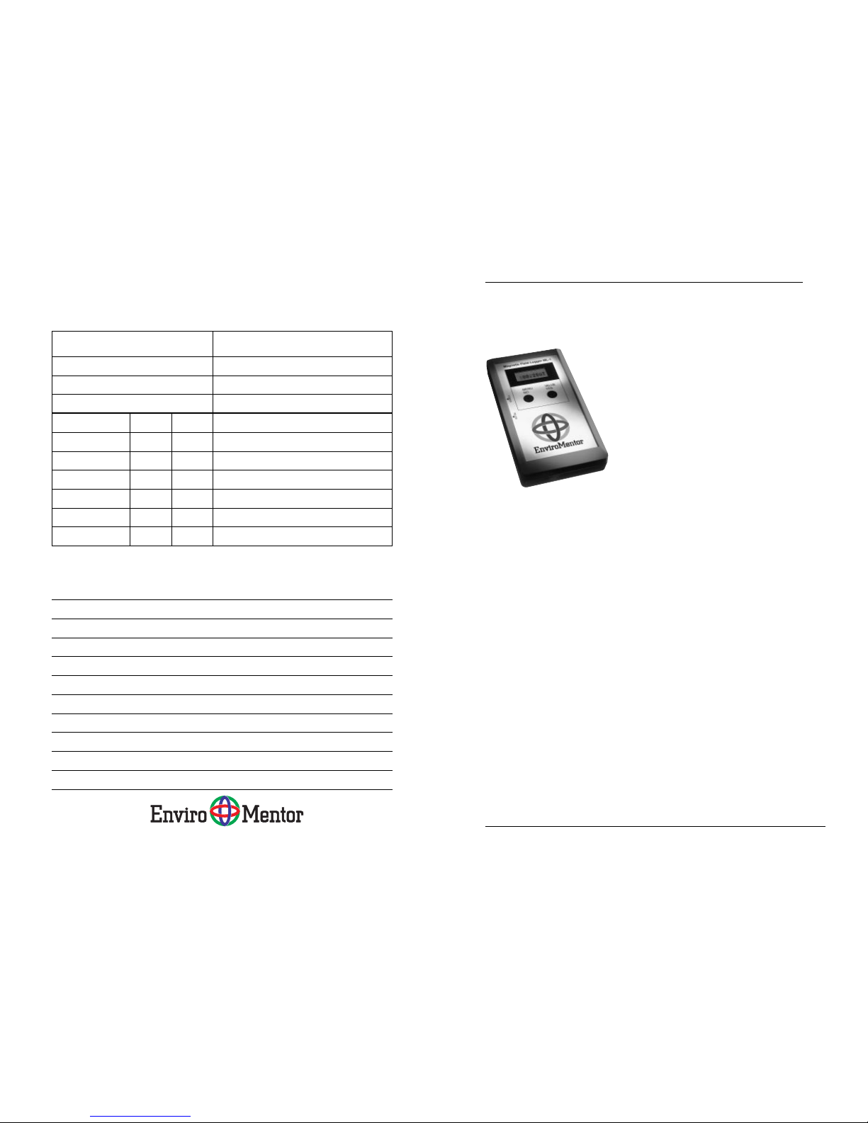
Magnetic Field Logger ML-1
measuring instrument.
Report form for measuring magnetic fields around an object
Magnetic field, 30 Hz–2 kHz Measuring equipment: Magnetic Field Logger
Object: Model: ML-1
Address: Room:
Measured by: Date:
30 cm 50 cm Comments
0°µT µT
90°µT µT
180°µT µT
270°µT µT
Background field µT µT
Notes
Report 98:7, Magnetic Field Logger © EnviroMentor AB, Gothenburg, Sweden
Page 4
ML-1ML-1
4 © Enviromentor AB 1999 reg. 98-013-1/Eng
You can use ML-1 whenever you want to measure or document magnetic fields, such as from
electrical installations, power cables, VDUs,
computers and other electrical equipment in the
office, industrial and home environments. Note
however that some of these objects create magnetic alternating fields that are outside the instrument’s frequency area.
ML-1 retains all measurement readings, even if
the battery runs out or is removed.
The ML-1 contains a band-pass filter for the
measurement of magnetic fields with a frequency of 50 Hz. The filter can be connected and
disconnected at any time, both for direct measurement and logging.
Report form B for measuring/registering magnetic fields in a room
Magnetic field, 30 Hz–2 kHz Measuring equipment: Magnetic Field Logger
Object: Model: ML-1
Address: Room:
Measured by: Date:
Direct measurement µT Registration µT
0 m 0.8 m 2 m Start Stop Int. (s) average Max
1
2
3
4
5
6
7
8
9
10
11
12
Notes
Report 98:6B, Magnetic Field Logger © EnviroMentor AB, Gothenburg, Sweden
Measurement point
Height above
floor
Page 5

ML-1ML-1
© Enviromentor AB 1999 reg. 98-013-1/Eng 5
2 Technical data
Measurement range 0,05 µT–100 µT
Accuracy ±10 % ±0,05 µT
Frequency range 30 Hz–2 kHz (-3dB)
Band-pass filter 4th sequence, Q-value
3.2, Connection time
3 seconds
Measurement method Triaxial,
RMS effective value
Memory locations 8,192
Measurement interval Manual, 1–150 sec-
onds
Dimensions, L x W x H 152 x 83 x 34 mm
Weight 260 g (incl. batteries)
Batteries 2 x 1.5 V LR6
Lithium batteries
CR 2032 or F2AWS
for the clock
Communication Serial RS232, 9600
baud, 8 bits, no par-
ity, no handshake
Power consumption 38 mA in clock
mode, 25 mA dur-
ing measurement
and 45 mA during
transmission
Temperature range -10 to +50 °C
Other Microprocessor,
10 bit A/D-converter,
three-dimensional
sensor, EEPROM
memory, clock, cal-
endar
Report 98:6A, Magnetic Field Logger © EnviroMentor AB, Gothenburg Sweden
Sketch of the room with measurement points marked.
Report form A for measuring/registering magnetic fields in a room
Page 6

ML-1ML-1
6 © Enviromentor AB 1999 reg. 98-013-1/Eng
CE assurance
Our product satisfies the demands of the Low
Voltage and EMC directive as well as the following EMC standards:
EN 50 081-1:1992 Emissions standard
class B
EN 50 082-1 Immunity standard
Manufacturer EnviroMentor AB
Box 5124
SE-402 23 Gothenburg
Sweden
Traceability
Traceability means that it should be possible to
relate a measurement result to national or international standards via an unbroken chain of
comparisons.
EnviroMentor AB’s ca-
libration system
The Swedish National
Testing and Research
Institute
The Swedish Board
for Accreditation and
Conformity Assess-
ment, SWEDAC
FFV Measurement techn.
Laboratories accredited by SWEDAC in accordance with
Swedish legislation.
The accredited Swedish laboratories satisfy the demands
of SS-45001 (1989) and ISO/IEC standard 25 (1990:E).
Traceability chart.
7 Report forms
On the following pages you will find report form
templates for measuring magnetic fields. Copy
the templates, fill them out and then file them
in a folder. You can then go back and make
comparisons with previous measurements.
Section 4 gives examples of how to carry out
measurements, while subsection 4.3 details how
to fill out the report forms.
Report form for measuring
magnetic fields around an object.
Report form for measuring/registering magnetic fields in a room.
Report form for measuring magnetic fields around an object
Magnetic field, 30 Hz–2 kHz Measuring equipment: Magnetic Field Logger
Object: Model: ML-1
Address: Room:
Measured by: Date:
30 cm 50 cm Comments
0°µT µT
90°µT µT
180°µT µT
270°µT µT
Background field µT µT
Notes
Report 98:7, Magnetic Field Logger © EnviroMentor AB, Gothenburg, Sweden
Report 98:6A, Magnetic Field Logger © EnviroMentor AB, Gothenburg Sweden
Sketch of the room with measurement points marked.
Report form A for measuring/registering magnetic fields in a room
Report form B for measuring/registering magnetic fields in a room
Magnetic field, 30 Hz–2 kHz Measuring equipment: Magnetic Field Logger
Object: Model: ML-1
Address: Room:
Measured by: Date:
Direct measurement µT Registration µT
0 m 0.8 m 2 m Start Stop Int. (s)average Max
1
2
3
4
5
6
7
8
9
10
11
12
Notes
Report 98:6B, Magnetic Field Logger © EnviroMentor AB, Gothenburg, Sweden
Measurement point
Height above
floor
© Enviromentor AB 1999 reg. 98-013-1/Eng 19
Page 7

ML-1ML-1
© Enviromentor AB 1999 reg. 98-013-1/Eng 7
3 Use
3.1 Menu
ML-1 has a menu that you can move around in
using the two function keys. The main menu contains four submenus - clock mode, measurement
mode, registration mode and transmission mode.
The full menu tree is shown below. You can use
this for reference purposes once you are familiar
with the instrument. Sections 4 and 5 describe
step by step how to use the various functions.
13:17 Set? __/08/06
Set year
94/__/06
LOGG Loc0001
ClearM?
Int001s
StartL? 00.47**
DUMP StartD?
A
Power on
A
D
DDA
B
B
C
C
A
Sure?
Set
interval
Set day
Set month
etc
Clear memory
Display is blank
while data is being
transferred
Clock mode
Measure mode
Log mode
Dump mode
Left button (MENU/NO)
Right button (VALUE/YES)
00.47uT
00.23uT
50
B
Menu structure in ML-1.
6 References to authorities and organisations
Publication Publisher/Author May be ordered from
Magnetic fields and health
risks based on what we
know
The National Electrical
Safety Board
Elsäkerhetsverket
Box 1371
SE-111 93 STOCKHOLM
SWEDEN
Tel. +46 8-519 112 00
Fax. +46 8-519 112 01
Cancer and magnetic fields
in workplace
The Swedish Trade
Union Confederation
LO-distribution
Strömsätragränd 10
SE- 127 35 SKÄRHOLMEN
SWEDEN
Tel. +46 8-796 25 00
Questions and answers about
electric and magnetic fields
associated with the use of
electric power
National Institute of Environmental Health Sciences and
U.S. Dep. of Energy
Superintendent of Documents
U.S. Goverment
Printing Office
WASHINGTON, D.C. 20 402
USA
Tel. +1 202-512-1800
A report of non-ionizing
radiation
Microwave News
Microwave News
Louise Slesin
P.O. Box 1799
Grand Central Station
NEW YORK, N.Y. 10 163
USA
+1 212-517-28000
+1 212-734-0316
mwn@pobox.com
18 © Enviromentor AB 1999 reg. 98-013-1/Eng
Page 8

ML-1ML-1
8 © Enviromentor AB 1999 reg. 98-013-1/Eng
3.2 Setting the clock
When the instrument has been connected, it
will be in clock mode. To set the clock:
• Press YES. Set? appears in the display.
• Press YES.
YY/MM/DD appears in the display
• Press YES until the correct year is displayed,
then press NO
• Press YES until the correct month is displayed,
then press NO
• Press YES until the correct day is displayed,
then press NO
HH:MM appears in the display
• Press YES until the correct hour is displayed,
then press NO
• Press YES until the correct minute is displayed, then press NO
The clock is now set (the seconds are always set
to zero) and the instrument reverts to clock mode
in the main menu.
3.3 Direct measurement
• Start up the instrument with the switch
• Press the NO button once.
• Press YES once if you want to disconnect
the 50 Hz filter.
• Press YES again to connect the 50 Hz f ilter.
ML-1 now measures the magnetic fields and displays the effective value in µT. This value is updated at 1 second intervals. ML-1 can be pointed
in any direction in relation to the magnetic field
source as it has a three-dimensional sensor. “50”
appears in front of the measurement reading in
the display if the filter is connected.
The Q-value of the band-pass filter
is 3.2, which means that the signal is
attenuated approximately 30 times
at 150 Hz.
© Enviromentor AB 1999 reg. 98-013-1/Eng 17
A modern office has many sources
of magnetic fields.
5 How magnetic fields arise
Magnetic fields are caused by electrical currents and always occur in continuous closed
paths around the currents that cause them. A
live conductor gives rise to a magnetic field,
the strength of which is always proportional to
the current in the conductor. Magnetic fields
are usually depicted with the aid of field lines.
The strength of the magnetic field is constant
along the conductor in closed paths around the
live conductor. In the event of other sources,
magnetic fields tend to have a complicated appearance which usually cannot be calculated
but have to be measured instead. The unit used
to measure the magnetic flux density is called
the tesla [T]. Magnetic fields can be caused by
electrical devices and installation cables. In certain cases, stray currents can give rise to magnetic fields. In Sweden, for example, the electricity systems generally entail four conductors
leading to each building, which can result in
major problems with currents of this type. The
decay current can pass through the neutral conductor as intended, but it can also pass through
the earth conductor and into the plumbing pipework to the transformer’s earth point. This increases the magnetic field both along the path
of the stray current and along the supply cable.
It is also commonplace for stray currents to exist in computer networks. As well as causing
magnetic fields, they can also lead to communication problems. In industrial environments,
common sources include welding equipment,
electric motors and cable clusters.
Straight conductor, I =1A
At 1 m from the conductor, the
magnetic flux density is 0.2 µT.
Page 9

ML-1ML-1
© Enviromentor AB 1999 reg. 98-013-1/Eng 9
3.3.1 Transmission during direct measurement
During direct measurement, the readings are
transmitted via the RS232 port at one second
intervals. The readings can be received by a
computer with communication software or
some similar terminal program. In the computer, the readings are stored as a text file on the
hard disk. From there, they can be imported
into a calculation program and used to produce
diagrams or statistical calculations for the
measurement. Connect the accompanying cable
between RS232 on the instrument and one of
the ports (COM 1, COM 2 or COM 3) on the
computer. The settings for the communication
software are listed in subsection 3.3.2 below.
3.3.2 Transmission protocol during direct
measurement
During direct measurement, the readings are transmitted as in the following example: 01.75 01.74
012.0, i.e. ML-1 separates each reading with a space.
Most communication programs can receive measurement data, e.g. Terminal in Windows.
3.4 Registering readings (Logging)
• Start up the instrument
• Press NO twice. LOGG appears.
• Press YES. LocXXXX shows how many
memory locations have been used. Loc8192
means that the memory is full.
• Press NO. ClearM appears.
• Press NO if you want to store additional val-
ues or YES if you want to delete the memory. IntXXX now appears, which is the current
measurement interval.
• Press YES until the desired interval is dis-
played. You can select from Manual, 1, 2, 3,
4, 5, 10, 20, 40, 80, 100 and 150 seconds.
Software settings:
Transfer speed 9600 baud
Data bits 8
Parity none
Flow regulation/
handshake none
You also have to select the correct
serial communications port in the
software (COM1, COM2…).
Maximum measuring time at
different measurement intervals [s].
[s] max. measuring time
1 2 hour 17 mins
2 4 hours 23 mins
3 6 hours 50 mins
4 9 hours 6 mins
5 11 hours 23 mins
10 22 hours 46 mins
20 1 day 21 hours 46 mins
40 3 days 19 hours 12 mins
80 7 days 14 hours 24 mins
100 9 days 11 hours 34 mins
150 14 days 5 hours 20 mins
16 © Enviromentor AB 1999 reg. 98-013-1/Eng
Photocopier
1 North Street Porter’s office
J. Smith 10 March 1995
20 10 During copying
30 10
40 20
30 10
33
The background fields are OK, but perhaps should
screen off the copier or rearrange the furniture.
Example of a completed report form for measuring
magnetic fields around an object.
5. Conclude registration after e.g. a day and
continue in the same manner with the other
measurement points.
4.3 Example of report form for
measuring magnetic fields
When you measure magnetic fields, you should produce a report form which can act as a basis for any
remedial action. Below is an example of a completed report form. Report form templates which you
can copy can be found at the back of these user instructions. Once you have filled out the forms, they
should be filed in a folder. You can then go back and
make comparisons with previous measurements.
Report form for measuring magnetic fields around an object
Magnetic field, 30 Hz–2 kHz Measuring equipment: Magnetic Field Logger
Object: Model: ML-1
Address: Room:
Measured by: Date:
30 cm 50 cm Comments
0°µT µT
90°µT µT
180°µT µT
270°µT µT
Background field µT µT
Notes
Report 98:7, Magnetic Field Logger © EnviroMentor AB, Gothenburg, Sweden
Page 10

ML-1ML-1
10 © Enviromentor AB 1999 reg. 98-013-1/Eng
• Press NO when you have selected the interval. StartL? now appears.
• Press YES to start registration.
• Press YES once if you want to connect the
50 Hz filter.
• Press YES again to disconnect the 50 Hz f ilter.
ML-1 now measures the magnetic field and updates the reading in the display at the selected
interval. After the reading, ** appears, which
indicates that registration is in progress. When
the 50 Hz filter is connected, “50” appears in
front of the measurement reading in the display.
When connecting and disconnecting the filter,
it takes approximately 3 seconds for the reading to stabilise.
• Press NO if you want to interrupt registration. The instrument reverts to the measurement mode in the main menu.
Y ou can no w commence a ne w measurement series,
provided you have sufficient memory space. Press
NO until LOGG appears, then repeat the above
procedure. If you want, you can select a different
interval. The maximum measuring time depends
on the measurement interval you have selected.
The table to the left shows the maximum measuring
times for measurement series with different intervals.
Note!
The instrument retains the
stored readings, even if the
batteries run out or are removed.
ML-1 connected to a computer.
Example of completed report form for measuring/registering magnetic fields in a room.
wardrobe
desk
1
2
3
4
0.01 0.02 0.01 19:30 07:30 150 0.02 0.05
0.02 0.03 0.01 18:30 06:30 150 0.01 0.03
0.2 0.02 0.01 18:00 06:00 150 0.05 0.21
0.3 0.02 0.01 18:15 06:15 150 0.03 0.3
0.02 0.01 0 19:10 07:10 150 0.015 0.02
5
3 High Street 123
P. Jones 13 May 1998
some distance away, and magnetic fields can
penetrate almost all building materials.
4.2 Logging magnetic fields
Below is a suggestion as to how to measure the
variations in the magnetic field in a room within the frequency range 30 Hz to 2,000 Hz.
1. Draw a sketch of the room and mark the points
where you want to register the variations in
the field strength.
2. Check that the clock is set and that the battery
is charged.
3. Position the instrument at measurement point
1, mark this on the sketch and note the start
time on the report form.
4. Set the measurement interval and start the
registration process (see subsection 3.4).
Report 98:6A, Magnetic Field Logger © EnviroMentor AB, Gothenburg Sweden
Sketch of the room with measurement points marked.
Report form A for measuring/registering magnetic fields in a room
Report form B for measuring/registering magnetic fields in a room
Magnetic field, 30 Hz–2 kHz Measuring equipment: Magnetic Field Logger
Object: Model: ML-1
Address: Room:
Measured by: Date:
Direct measurement µT Registration µT
0 m 0.8 m 2 m Start Stop Int. (s)average Max
1
2
3
4
5
6
7
8
9
10
11
12
Notes
Report 98:6B, Magnetic Field Logger © EnviroMentor AB, Gothenburg, Sweden
Measurement point
Height above
floor
© Enviromentor AB 1999 reg. 98-013-1/Eng 15
Page 11

ML-1ML-1
© Enviromentor AB 1999 reg. 98-013-1/Eng 11
Example of the presentation of a 15-point measurement in the “Field Analyzer” program.
3.5 Manual registration of the
measurement readings
(15-point measurement)
Set the interval manually and start registration as
described in subsection 3.4. ML-1 will now measure the magnetic field and update the measurement reading in the display at 1 second intervals.
In the display, *> appears after the measurement reading, which indicates that ML-1 is in standby mode.
• Press YES to register the f irst point. The display
now shows 01 after the measurement reading
for a short while before reverting to *>.
• Press YES ag ain to re gister the second point, and
the display will show 02. When the 15th and last
point has been registered, the instrument will revert automatically to the LOGG menu.
4 Measurement examples
4.1 Direct measurement of magnetic fields
Below is a suggestion as to how to measure the
magnetic field in a room within the frequency
range 30 Hz to 2,000 Hz.
1. Start by carrying out a preliminary measurement with all the pieces of electrical equipment switched on and make a rough estimate
of what field sources are present in the room.
Draw a sketch of the room. Then measure a
number of points at 1-3 metre intervals and
write down the values measured on the sketch.
Measure the magnetic field at floor level as
well as at 0.8 and 2 meters above the floor.
2. Then carry out a measurement with all the
electrical apparatus in the room switched off
to get an idea of the extent of the background
fields in the room. Remember that it is probably not sufficient simply to switch off the pieces of apparatus - you will usually need to unplug them in order to completely eliminate the
fields. In some cases, the background magnetic fields can be more powerful than the magnetic fields from the apparatus in the room.
3. Connect the pieces of apparatus one at a time
and measure the magnetic fields in the directions 0°, 90°, 180° and 270° at distances of
30 cm and 50 cm from the outer edge of the
piece of apparatus in question or in the direction the operator is facing (see figure) . Summarise the measurement readings in a report
form. An example of how to fill out a report
form can be found on page 16. You must not
subtract the background values of the magnetic fields from the measured values. They
should always be noted as a comparison.
4. Analyse the measurement readings and assess the need for remedial action, such as rearranging the furniture in the room and/or moving pieces of electrical apparatus. The sources of the magnetic fields may be located
50 cm
50 cm
Overhead view.
Side view.
14 © Enviromentor AB 1999 reg. 98-013-1/Eng
Page 12

ML-1ML-1
12 © Enviromentor AB 1999 reg. 98-013-1/Eng
3.6 Transmitting measurement
series (Dumping)
To transmit measurement series to a computer:
• Connect ML-1 to the computer using the accompanying cable and the adapter if required. Use the COM 1,
COM 2 or COM 3… port on the computer.
• Start up the instrument.
• Press NO three times. DUMP appears.
• Press YES. StartD appears.
• Start up the “Field analyzer” program on the
computer
• Select instrument ML-1.
• Select the “Communication” menu.
• Select the correct serial communication port
(COM 1, COM 2 or COM 3…) in the software
• Select “Communication” again
• Select “Start ML-1 dump”.
• Name the file. The pr o gram is now ready to
receive series of measurements.
• Press YES on ML-1. Transmission starts immediately. The display remains blank while transmission is in progress. Transmission takes place
at a rate of around 50 readings a second. Once
transmission is completed, the instrument reverts
to transmission mode in the main menu.
3.6.1 Transmission protocol during dumping
Data transmission during dumping comprises
ASCII characters, i.e. normal text in accordance
with the following:
Every measurement series begins with a plus sign.
At a 100 second interval, “00” appears in the display,
at 150 seconds “50” appears and during manual
logging “15” appears.
This is followed by the start time, date and interval
for the measurement series as well as a space. These
are followed by the readings in µT, separated by spaces.
A complete series is concluded with a space, with
the next series beginning with a plus sign. The final
series is concluded with an asterisk.
Note!
The analysis program can
process a maximum of 99
measurement series.
© Enviromentor AB 1999 reg. 98-013-1/Eng 13
Example:
+301514079701 00.08 00.07 00.06 ……
……00.10 +020915079740 00.05 00.45 …00.33 *
indicates that the first measurement series began
at 15.30 on 14/07/1997 with a measurement interval of 1 second and produced the readings 0.08 µT;
0.07 µT; 0.06 µT… 0.1 µT, while the final measure-
ment series began at 09.02 the following day with
a measurement interval of 40 seconds and produced the series 0.05 µT; 0.45 µT … 0.33 µT.
3.7 Deleting the memory
Once you have transmitted the readings to the computer, it may be a good idea to delete the memory .
• Follow the instructions under point 3.4 (registering readings) until Clear? appears.
• Press YES. Sure? appears.
• Press YES. The memory has now been deleted.
• Press NO twice to revert to the measurement
mode in the main menu.
3.8 Changing the batteries
When the battery symbol is displayed to the left
of the measurement reading, the batteries should
be replaced (2 x 1.5 V LR6). If the batteries run
out while logging is in progress, the logging process will be interrupted but the readings will be
saved. If the batteries start to run low while ML-1
is connected to a computer via the interface cable,
it may be impossible to exit the direct measurement mode. This is because power consumption
is considerably higher during transmission. In this
case, the instrument goes back up in the menu in
order to prevent transmission errors. Disconnect
the RS232 cable and check that it is possible to
move forward to the DUMP mode in the menu. If
the problem recurs when you reconnect the cable,
the batteries should be replaced. The instrument
has an integral back-up battery that enables you to
replace the batteries without losing any data.
Battery symbol.
Note!
Remember that power consumption is considerably
greater when the RS232 port
is in use.
 Loading...