

Page 1
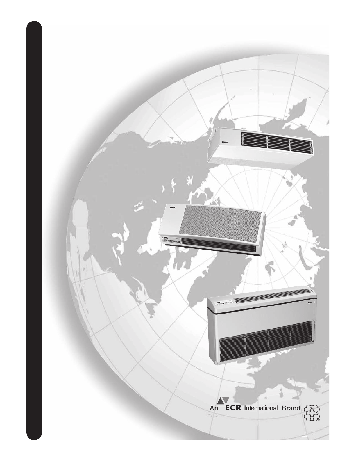
FCP/FHP,
WCP/WHP,
andCCP/CHP
EMIDUCTLESSSPLITSYSTEM
AIRHANDLERS
CEILINGMOUNTEDAIRHANDLER
(CHP)
Enviromaster International LLC
INSTALLATION,OPERATIONANDMAINTENANCEMANUAL
5780 Success Dr.
Rome, NY 13440
www.enviromaster.com
WALLMOUNTEDAIRHANDLER
(WCP/WHP)
FLOORMODELAIRHANDLER
(FCP/FHP)
An ISO 9001-2000 Certified Company
P/N# 240004373, Rev. 1.6 [9/06]
P/N# 240004373, Rev. 1.5 [9/05]
Page 2
EMI DUCTLESS SPLIT SYSTEM AIR HANDLERS
INSTALLATION, OPERATION, AND MAINTENANCE MANUAL
P/N# 240004373, Rev. 1.6 [9/06]
TABLE OF CONTENTS
Common To All Air Handlers..1-7 Continued 21-32
Safety Instructions .................................................. 2
The EMI Air Handler Family ....................................3
Installer Supplied Items ...........................................3
Items for Consideration ............................................4
Controls and Components ......................................4
Optional Controls/Components ...............................4
High Volt Electrical Wiring .......................................4
Low Volt Electrical Wiring ....................................5-7
Dip Switch Settings ..................................................5
Shipping Damage MUST be Reported to the Carrier IMMEDIATELY!!!
Examine the exterior. Remove cover and examine compressor and piping for signs of damage.
This manual is intended as an aid to qualified service
personnel for proper installation, operation, and maintenance of the EMI ductless split system floor, wall, corner,
or ceiling mounted air handler. Read these instructions
thoroughly and carefully before attempting installation or
operation. Failure to follow these instructions may result
in improper installation, operation, service or maintenance,
possibly resulting in fire, electrical shock, property damage,
personal injury, or death.
Floor Model Air Handler (FCP/FHP) ..................
Ceiling Mounted Air Handler (CCP/CHP) ........13-14
Wall Mounted Air Handler (WCP/WHP) ...........15-17
Preperation for Start-up ........................................18
Unit Mount Control Start-Up ............................18-20
Wall Thermostat Start-Up ................................21-22
Test Unit Performance Data ..................................23
Maintenance and Troubleshooting ................. 24--27
Warranty ...............................................................28
Specific Unit Installation
SAFETY INSTRUCTIONS
WARNING
!
Read all instructions before using the EMI Air Handler. Install or locate this unit only in accordance with
these instructions. Use this unit only for its intended
purpose as described in this manual.
!
8-12
TO THE INSTALLER
(1) Retain this manual and warranty for future refer-
ence.
(2) Before leaving the premises, review this manual to
be sure the unit has been installed correctly and run
the unit for one complete cycle to make sure it func
tions properly.
To obtain technical service or warranty assistance during or after the installation of any EMI
unit, check our website @ www.enviromaster.com
or call your installing contractor or distributor. Our
technical service department may be contacted at
1-800-228-9364.
When calling for assistance, please have
the following information ready:
• Model number _____________________
• Serial number _____________________
• Date of installation _________________
Made in Rome, New York, USA
-
Check the rating plate on the EMI Air Han-
dler before installation to make certain the
voltage shown is the same as the electrical
supply to the unit. Installing a unit with the
wrong Voltage may void the warranty!
The EMI Air Handler must be connected to a
properly grounded electrical supply. Do not fail
to properly ground this unit.
Turn off the electrical supply before servicing
the EMI Air Handler.
Do not use the EMI Air Handler if it has dam-
aged wiring, is not working properly, or has been
damaged or dropped.
[Save these instructions]
Recognize this symbol as an indication
!
2
of Important Safety Information.
E-mail: [email protected]
!
Page 3
COMMON TO ALL AIR HANDLERS
SAFETY INSTRUCTIONS Continued
The manufacturer of this unit will not be liable for any
damages caused by failure to comply with the installation
and operating instructions outlined in this manual.
A rating plate identifying this EMI Air Handler can be
found on the unit. When referring to your unit, always have
the information listed on the rating plate readily available.
DANGER
!
Completely read all instructions prior to assembling, installing, operating, or repairing this product.
Inspect all parts for damage prior to installation and
start-up. The EMI Air Handler must be installed only
by qualified installation personnel.
Check Unit Rating Plate for Proper Power Supply!
THE EMI AIR HANDLER FAMILY
Materials of Construction:
1. Cabinet fabricated of 20-gauge galvanneal steel
with an off-white powder coat matte finish
• Plastic tops, fronts constructed of a high impact
polystyrene (Hips) material
2. Discharge grill construction of high temperature
Noryl plastic (WHP/WCP ONLY)
• Annodized Aluminum discharge grill FHP/FCP &
CHP/CCP
3. Condensate drain pan constructed of anticorrosive
G90U galvanized steel
The EMI Air Handler is available as a (Dx) direct expansion straight cool, heat pump – floor, wall, or ceiling units
– and two-pipe chilled water fan coil model. The air handler
offers ease of installation, operation, and service, and can
be matched with EMI’s SCC/SHC single-zone condensing
unit or either of the company’s multi-zone outdoor units,
the MC2/MH2 or MC4/MH4. Presently, EMI does not offer
a chiller unit that provides chilled water for the FCP, WCP
and CCP models.
All EMI A
development so designs and specifications may change
without notice. For more information on a specific air
handler, please refer to the corresponding section in this
installation manual or, for information on EMI
Units, please visit our website @ www.enviromaster.com
or contact the factory for the appropriate literature.
ir Handlers are subject to on going product
!
Condensing
THE EMI DUCTLESS SPLIT SYSTEM
AIR HANDLER FAMILY CONSISTS OF
FCP: Two-pipe chilled water fan coil floor unit avail-
able in 9,000, 12,000, 18,000, 24,000, 30,000,
36,000, 42,000, and 48,000 nominal Btuh capacities
(can be equipped with optional hot water coil).
FHP: Dx straight cool/heat pump floor unit, available
in 9,000, 12,000, 15,000, 18,000, 24,000, 30,000,
36,000, 42,000, and 48,000 nominal Btuh capacities
(with optional hot water coil).
WCP: Two-pipe chilled water fan coil wall unit avail-
able in 9,000, 12,000, 15,000, 18,000, 24,000, and
30,000 nominal Btuh capacities (hot water coil not
available).
WHP: Dx straight cool/heat pump wall unit available
in 9,000, 12,000, 15,000, 18,000, 24,000, 30,000,
and 36,000 nominal Btuh capacities (hot water coil
not available).
CCP: Two-pipe chilled water fan coil ceiling unit
available in 9,000, 12,000, 18,000, 24,000, 30,000,
36,000, 42,000, and 48,000 nominal Btuh capacities
(with optional hot water coil).
CHP: Dx Straight cool only Design Revision B
ceiling unit available in 9,000, 12,000, 18,000,
24,000, nominal Btuh capacities (with optional
hot water coil). (Design Revision is found in the
15th position of the model number.)
All EMI Air Handlers are backed by Enviromaster Inter-
national LLC and are tested and rated in accordance
with ARI standards 210/240 and UL 1995.
NOTE: CHP 12 and WHP 12/18/30 the units
built after 4/05 may need a Piston/Orifice
change at time of installation (factory supplied)
see page 12 (CHP), page 16 (WHP).
INSTALLER SUPPLIED ITEMS
• Low voltage wiring (18 awg required)
• High voltage power supply wiring
• Mounting fasteners (screws, wall anchors, etc.)
• Chilled water, condensate, and refrigerant piping
• Refrigerant (for interconnect charge)
• Hot water piping
• Flare nuts for refrigerant piping (FHP&CHP models only)
The Ductless Split System of Choice
3
www.enviromaster.com
Page 4
COMMON TO ALL AIR HANDLERS Continued
ITEMS FOR CONSIDERATION
Determine the best location for mounting the unit
for room air circulation. Locate outdoor and indoor
units as close together as possible.
Determine how power wire (high and low voltage)
condensate drainage, and refrigerant or water supply piping (for chilled water units) may be run to and
from unit. Knockouts on the air handler may be used
for this purpose.
FHP, WHP, and CHP ONLY - Ensure that intercon-
nect tubing is within the maximum allowable length
of 100’ including a maximum 35’ lift.
Serviceability should be considered when locating
the unit. The cabinet service panels must be able
to be removed without obstruction.
FCP/FHP/CCP/CHP - units can be equipped with
hot water coil.
CONTROLS AND COMPONENTS
Factory Installed or Supplied
Unit mount control panel (standard on FHP/FCP
and WHP/WCP optional on CCP/CHP) includes:
• ¾” backlit LCD display
• Adjustable operational range from 55° F to 95° F (in
one-degree increments)
• Anti-short cycle compressor protection
• Minimum compressor run time
• 60 second fan purge
• Freeze protection
• Audio feedback on control setting changes
• Universal control board for straight cool or heat pump
condenser operation
• Two-stage heating w/optional electric heat and heat
pump condenser
Fan operation: Auto (cycling), High and Low (constant)
• Dry Mode (operates cooling and electric heat simultaneously to remove humidity when optional electric
heat is selected)
• Test Operation for ease of testing after installation (all
timers eliminated)
• Non-volatile Backup Memory (control settings maintained indefinitely during power outages)
• 24V Low Voltage Transformer
IMPORTANT: Unit mounted controls are fully functional without the hand-held remote. See page 5
OPTIONAL CONTROLS & COMPONENTS
• Infrared hand held remote control
• Condensate pump (field or factory installed)
• Chilled water control valve (field installed)
• Wiring for normally closed/power open valve (24V
AC, 20VA max. or 8VA max. on units with condensate pumps)
• Open wire electric heaters in 3 sizes (factory
installed ONLY) with automatic reset high temperature cutout and redundant high temperature
fuse link
• Hydronic heat coil with sweat connections (consult
factory) FCP/FHP and CCP/CHP only
• 24V wall thermostat compatibility
• 24V thermostat
HIGH VOLT ELECTRICAL WIRING
(SEE THE APPROPRIATE AIR HANDLER SECTION FOR
SPECIFIC WIRING INFORMATION.)
All wiring should be in accordance with the National Electric
Code (NEC) and the local building codes.
1. Inspect the existing wiring for any deficiencies
such as cut or frayed wires. Replace such wiring
if found.
2. Check the unit rating plate for circuit ampacity and
breaker or fuse size. Use only HACR type break
-
ers. Select the proper wire for the ampacity rating.
3. Each unit must have a separate branch circuit protected by a fuse or breaker. Refer to the unit rating
plate for the proper wire and breaker or fuse size.
4. Connect the power wire to Black (L1) and the other
wire to Red/White (L2) at the power connector loca
tion. Connect the ground wire to the ground lug or
lead at the same location in the control box.
NOTE: On units rated 208/230V, the primary side of
the transformer is factory wired for 230V. For a 208V
power supply, the transformer tap must be changed
from orange to red. Refer to the wiring diagram located
on the unit.
IMPORTANT: When wiring the WHP 18–36 only: If
the job site voltage is 208V, the WHP high-low fan
speed switch must be rewired. Replace the black
and red fan motor wire connections with the blue
and orange fan motor wires respectively.
Made in Rome, New York, USA
See unit wire diagram for specific details.
4
E-mail: [email protected]
Page 5
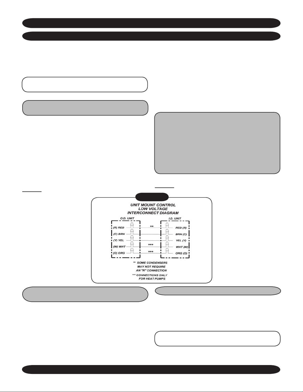
COMMON TO ALL AIR HANDLERS Continued
LOW VOLT INTERCONNECT WIRING FOR UNIT MOUNTED CONTROLS
As of 12/01/04, the 24V control transformer is located in
the air handler unit. This provides low volt control power
to both the air handler and condenser. Depending on the
models selected, the low Volt interconnect control wiring
may be effected.
Note: All low volt interconnect wiring must be at
least 18 awg.
COOLING ONLY UNITS
With or Without Heat
Cooling only units utilize two low Volt interconnecting wires
between the indoor and outdoor units. Wires (WCP/WHP)
or terminals (CCP/CHP/FCP/FHP) designated “Y” (yellow)
and “C” (brown) of the air handler should be connected to
the corresponding “Y” (yellow) and “C” (brown) wires or
terminals of the condenser. Other wires or terminals such
as “R” (red) or “O” (orange) may not be needed and should
be protected by a wire nut from making contact with the
junction box or other metal surfaces.
Refer to low
Figure 1 for unit mounted controls.
Volt interconnect diagram interconnect diagram
Figure 1
In addition to the “Y” and “C” connections required for
cooling, heat pumps require a reversing valve control wire
“O” (orange) that is energized in the cooling mode. If the
indoor unit has an electric heater then a ”W” (white) wire
connection may also be needed to energize the indoor
electric heat. Heat pumps models SHC require an “R”
connection between the indoor and outdoor unit to provide
power to the defrost control board in the condenser.
Heat pump models MH2 and MH4 do not require an “R”
connection after 12/01/04 since the transformer is located
in the air handler.
Note: Two-stage heating requires the combination of a
heat pump condenser and an indoor unit that is equipped
with an electric strip heater. The indoor electric heater
will energize as the second stage heat source, when the
room temperature falls by two degrees or more below the
set point, and also during the defrost mode for models
SHC. For limited range heat pumps models MH2 and
MH4, heat pump operation will cease when the outdoor
temperature falls below 35°F. In this case the electric
strip heater will remain sole heat source.
Refer to low Volt interconnect diagram interconnect diagram
Figure 1 for unit mounted controls.
HEAT PUMP CONNECTION - UNIT MOUNT
CONTROLS Two-Stage Heating
When connecting to a defrosting heat pump, such as
EMI model SHC, indoor units with electric heat utilize five
interconnecting low
outdoor units. When connecting to limited range heat pumps
such as EMI models MH2 and MH4 built after 12/01/04,
indoor units with electric heat utilize four interconnecting
low Volt wires. In this case the “R” (red) may not be needed
and should be protected by a wire nut from making contact
with the junction box or other metal surfaces.
The Ductless Split System of Choice
Volt wires between the indoor and
REMOTE THERMOSTAT CONTROLS
As of 12/01/04, the 24V control transformer is located in
the air handler unit. This provides low volt control power
to both the air handler and condenser. Depending on the
models selected, the interconnect control wiring may be
effected.
Note: All low Volt interconnect wiring must be at
least 18 awg.
Choosing a Remote Wall Mounted Thermostat: See
“Wall Thermostat Control” section Pg. 21-22
5
www.enviromaster.com
Page 6
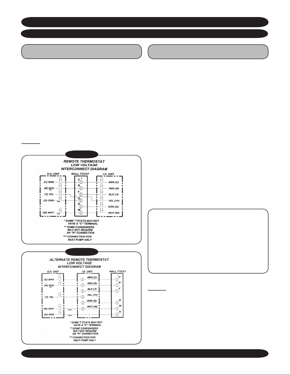
COMMON TO ALL AIR HANDLERS Continued
LOW VOLT INTERCONNECT WIRING Continued
COOLING ONLY UNITS
With or Without Heat
Depending on the thermostat required or selected,
cooling only air handles may utilize four to six low Volt
interconnecting wires between the indoor unit, thermostat
and outdoor unit. Some thermostats do not require the use
of the “C” (brown) connection. In this case, ensure that
any unused wires are insulated with a wire nut to prevent
them from making contact with the junction box or other
metal surfaces.
If the indoor unit has electric heat or hydronic heat then
a “W” connection is required between the thermostat and
indoor unit.
Refer to low Volt interconnect diagram interconnect diagram
Figure 2 for remote wall thermostat controls
Figure 2
HEAT PUMP CONNECTION - REMOTE THERMOSTAT
Two-stage Heating
Since heat pump mode is a function of the thermostat and
outdoor unit, connections between the indoor unit and
thermostat are the same as for cooling only applications.
Depending on the thermostat required or selected, the air
handler may utilize four to six low
wires between the indoor unit, thermostat and outdoor
unit. Some thermostats do not require the use of the “C”
(brown) connection.
Heat pump operation requires the connection of the “O”
(orange) terminal from the outdoor unit to the thermostat.
The reversing valve is energized in the cooling mode for
EMI models SHC heat pump condensers. If the indoor unit
has an electric heater then a “W” connection is also required
between the condenser and the indoor unit. For two-stage
heating, a “W” (sometimes called “W2”) connection is also
requires at the thermostat. Refer to the instructions provided
with the thermostat for the proper thermostat connections
for a two stage heat, single stage cooling system.
Ensure that any unused wires are insulated with a wire
nut to prevent contact with the junction box or other metal
surfaces.
Volt interconnecting
Figure 2 A
NOTE: Two-stage heating requires the combination
of a heat pump condenser and an indoor unit that
is equipped with an electric strip heater. The indoor
electric heater will energize as the second stage
heat source (the temperature is dependent on the
thermostat selected) and also during the defrost mode
for models SHC. For limited range heat pumps models
MH2 and MH4, heat pump operation will cease when
the outdoor temperature falls below 35°F. In this case
the electric strip heater will remain sole heat source.
Refer to low Volt interconnect diagram interconnect diagram
Figure 2 for remote wall thermostat control.
Made in Rome, New York, USA
6
E-mail: [email protected]
Page 7
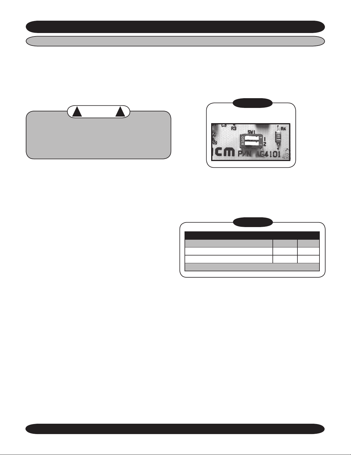
COMMON TO ALL AIR HANDLERS Continued (See Page 21 for Sequence of Operation)
DIP SWITCH SETTINGS (Unit Mount Control Only)
There are two dip switches on the relay board that of
fer different modes of operation. This allows the unit to be
matched with either a cooling only, cooling with electric
heat or heat pump condenser. Dipswitches are factory set
for a cooling only condenser. If the indoor unit is matched
with an EMI single zone or multi-zone heat pump condenser, the dipswitches will need to be changed.
WARNING
!
Before accessing the control compartment, disconnect power to both the indoor and outdoor units.
Failure to do so could result in serious injury or
electrical shock. DO NOT change dipswitch settings
with power applied to the unit.
• WHP/WCP- to gain access to the relay board, first
remove the return air grill from the front of the unit. Then
remove any panels or covers to the control section.
The relay board is located in the control box of the unit.
Set the dipswitches (Figure 3) according to the table
below(Figure 4).
• CHP/CCP- to gain access to the relay board, first
remove the return air grill from the bottom of the unit.
The relay board is located in the control section. Set
the dipswitches (Figure 3) according to the table
below(Figure 4).
• FHP/FCP- to gain access to the relay board, first
remove the return air grill from the bottom front of the
unit. The relay board is located in the control section.
Set the dipswitches (Figure 3) according to the table
below(Figure 4).
!
-
Figure 3
DIPSWITCH ON RELAY BOARD
Figure 4
DIP SWITCH SETTINGS
Switch 1 2
Cooling only Open Open
Cooling Electric or Hydronic Heat On On
Off = Open On = 1 or 2
Once the dipswitches are set and all covers and
panels are replaced, power can be applied to the equip
ment. When 24V power is applied, the microprocessor
will read the dipswitch setting.
The Ductless Split System of Choice
-
7
www.enviromaster.com
Page 8
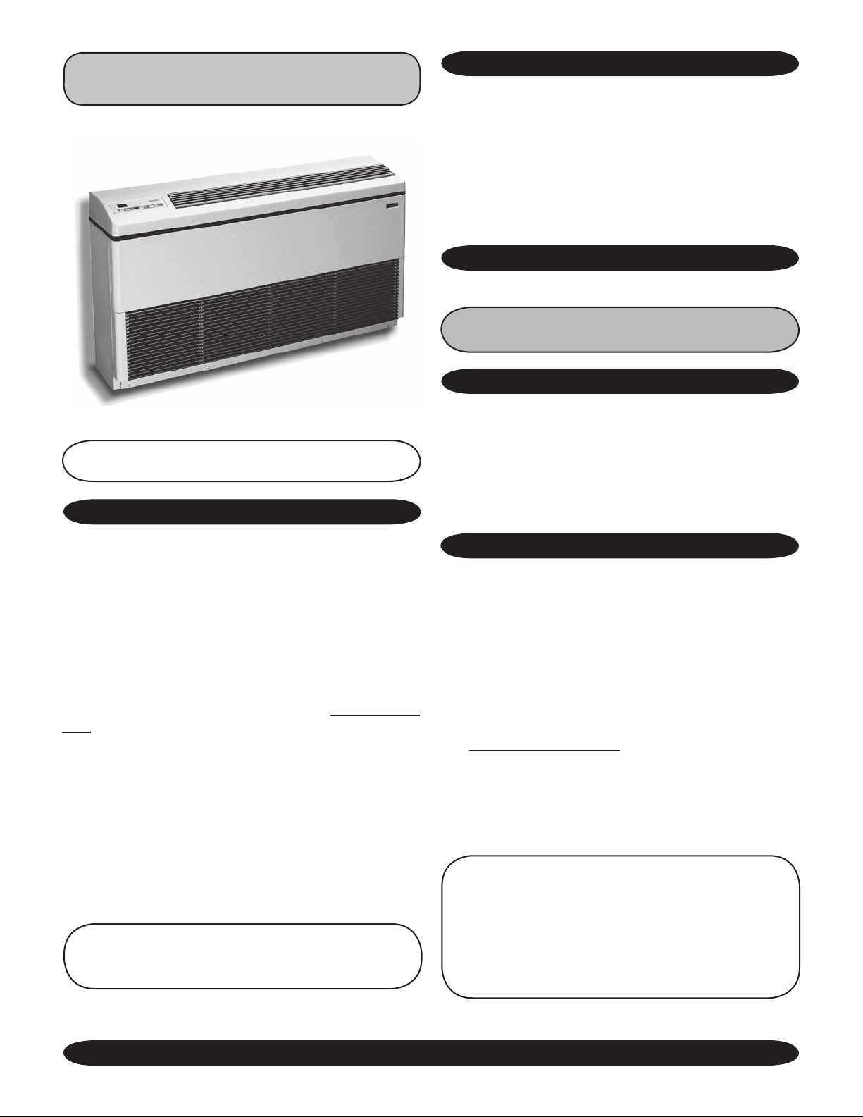
FLOOR MODEL AIR HANDLER
(FCP/FHP)
ITEMS FOR CONSIDERATION
• EMI’s FHP evaporator requires 24V power for control
operation. (As of 12/01/04 a transformer is supplied
in the indoor unit).
• Ensure that the FHP interconnect tubing is within
a maximum allowable length of 100’ including, a
maximum 35’ lift.
• Liquid line filter dryer.
OPTIONAL CONTROLS & COMPONENTS
• Fan-Induced fresh air (FHP only)
See page 4 in Common Section for
complet list of Optional Controls/Components
MOUNTING PREPERATION
1. Check equipment for damage before mounting.
NOTE: The FHP utilizes a molded plastic top. DO
NOT sit or stand on it as you may damage the unit.
DESCRIPTION
The FHP 09-30 and 36-48 is available in two cabinet
sizes with nine capacities in Cooling Only or Heat Pump
(depending on condenser match).
FHP units are equipped with a unit mounted control
that allows the unit to operate in either straight cool or heat
pump mode. The unit is configured by changing dip switch
settings prior to installation. FHP units are compatable with
any AmericaSeries outdoor unit.
FHP units are shipped from the factory set in cooling
only mode and will need to be reset for heat pump applications.
The FCP is a Chilled Water model with electric or hot
water heating options and is compatible with any chilled
water source of matching capacity.
A unit mounted, electronic, digital control is standard
and an optional infrared handheld remote control is avail
able. Fresh air knockouts and anti-short cycle protection
are standard features on all FCP/FHP units
NOTE: If equipped with hydronic heat, the FHP will
only operate as a single-stage heating unit and not
as a two-stage heating unit.
2. Determine the best location for mounting the unit for
optimum air circulation.
3. Locate the indoor and outdoor units as close together
as possible. (See outdoor unit requirements.)
UNIT MOUNTING
The FHP/FCP is designed to sit directly on a finished floor,
flush against a wall. Moldings or baseboard must be cut to
allow the unit to be mounted flush against the wall.
Units that are installed without a wall box should be test
fit for wiring and tubing positions. Place the unit against
the wall with the front panels removed. Mark the connec
tion locations on the wall. Shim the unit, if necessary, for
square floor to wall positioning.
4. Determine the following:
• Power supply wire routing
• Interconnect refrigerant piping routing
• Chilled water and condensate piping routing (FCP)
• Low voltage control interconnect wiring
• Fresh air ducting (if required)
-
NOTE: FHP 42 contains Kit# 550-121 that includes
a .073” I.D. orifice. The existing factory installed
.078” orifice must be replaced with the one suppiled in the kit when matching an Air Handler with
a 36,000 Btuh Condensing Unit. (See the instructions attached to Kit# 550-121 for proper conversion procedure.)
-
Made in Rome, New York, USA
8
E-mail: [email protected]
Page 9
FLOOR MODEL AIR HANDLER (FCP/FHP) Continued
MOUNTING & INSTALLATION Continued
5. Tubing may be run through the knockouts located on
the bottom left rear (room side) of the unit, as well
through knockouts in the back of the unit.
6. Consider future servicing of the unit when determin
ing mounting location. All FHP service is performed
by removing the front (room side) panels.
OPTIONAL FRESH AIR
Units with a wall box (field supplied only for fresh air)
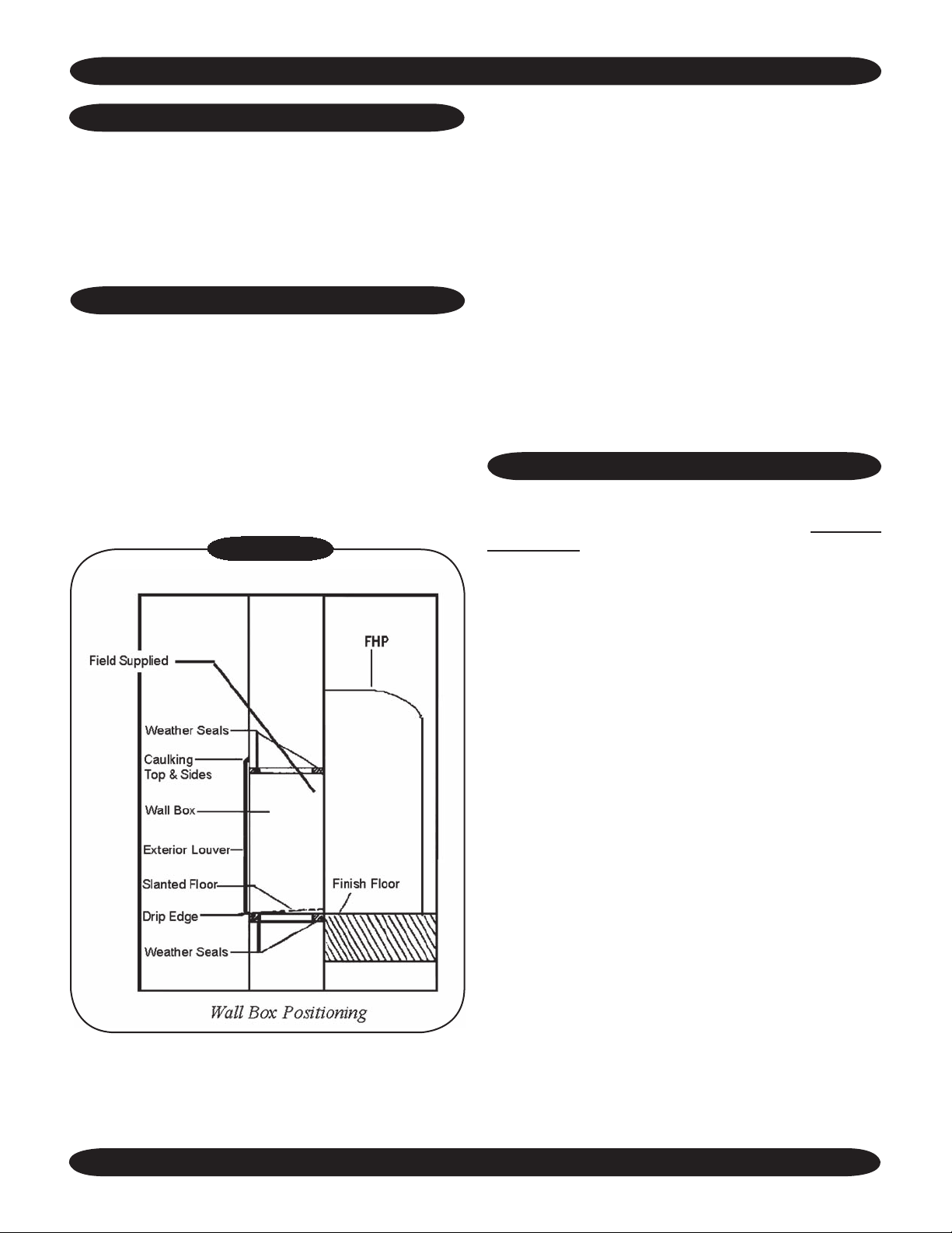
must be checked to ensure the unit is level and the floor of
the wall box is pitched down and away from the unit. The
drip edge of the wall box must clear the edge of the finished
outside wall (See Figure 7 – Wall Box Positioning). EMI
recommends that all electrical, refrigerant, and condensate
lines are routed through the wall or floor to the correct locations to use the knockouts before the unit is mounted in
place.
Figure 7
-
If a fresh air connection is necessary for this FHP/FCP
installation, please note the following:
• All ducts, collars, and dampers are field supplied. The
back side has a 4” knockout for a fresh air duct.
• Block the opening during installation to prevent foreign
objects from getting into the unit.
• The duct should be installed with a slight downward
pitch away from the unit to prevent moisture from en
tering the unit.
Secure the unit to the wall using lag screws or other
appropriate anchor devices. Then connect all wiring and
tubing connections.
REFRIGERANT PIPING
The FHP is equipped with a Flo-Rater/Piston Expansion Device. Connections are male flare type (flare nuts
not included).
-
The suction line (large) must be insulated the entire
length with closed cell, foam tube insulation. Do not insulate
the liquid line (small). Connect the outdoor unit according
to the instructions supplied with unit.
All horizontal piping runs must be level and without
dips to trap the oil.
The Ductless Split System of Choice
9
www.enviromaster.com
Page 10
FLOOR MODEL AIR HANDLER (FCP/FHP) Continued
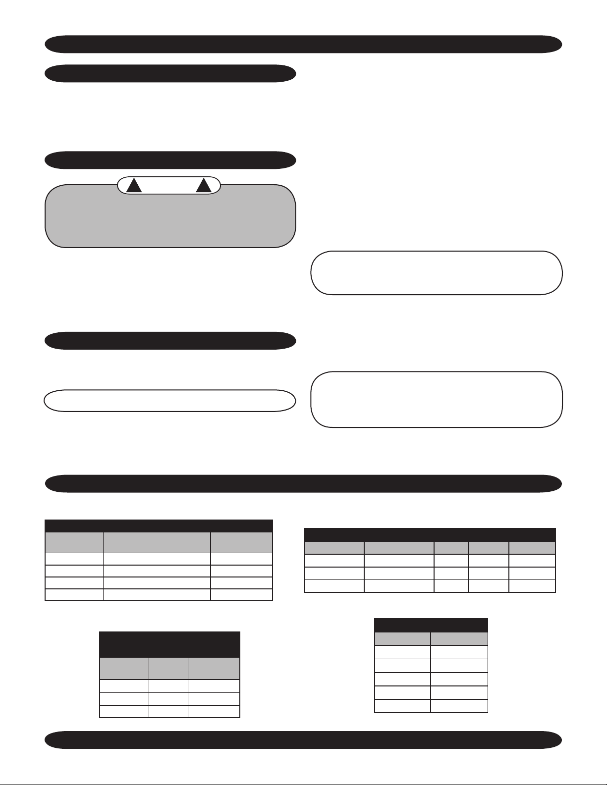
PIPING DO’S AND DON’TS
• Avoid piping on a rainy day.
• Use refrigerant grade copper tubing.
• Use a tubing bender and avoid unnecessary bending.
• Cap ends of lines until ready for final connections.
REFRIGERANT PROCESSING
WARNING
!
!
It is illegal to discharge refrigerant into the
atmosphere. Use proper reclaiming methods
and equipment when installing or servicing
this unit.
Finish all pipe connecting before proceeding to charg
ing the system. Follow the instructions in the outdoor unit
for line evacuation, opening service valves, and final charge
adjustments. Operation charts and charge tables can be
found in the EMI Condenser IOMs.
CHILLED WATER PIPING
• Follow manufacturer’s instructions for any field installed control valves.
• Unit control is provided for a 24V normally closed/
power open valve (20VA max.)
• Consult factory if other types of valves are used.
• Insulate supply and return piping with closed cell
foam tube insulation.
• Avoid unnecessary bends or kinks (use a tubing
bender)
• Make sure glycol solution is compatible with all
valves, unions and compression fittings. Ethylene
or propylene is recommended.
• Bleed air from system prior to start-up, units are
equipped with a standard air bleeder on the highest
point on the unit piping.
-
CAUTION:
Disconnect power when bleeding
system. Make certain liquid does not contact any
electrical components.
Finish all piping before balancing the system. Bleed
system, adjust temperature and/or water flow rate until
desired results are achieved.
Standard connections provided are sweat type. See
specifications for line size and actual unit connections.
NOTE: Water pipe sizes are given in I.D.
• Use pipe unions or compression fittings to aid
future service. Use isolation valves to aid in unit
removal.
• Connections can be brazed or soft solder type.
FCP/FHP DIMENSIONS AND SPECIFICATIONS
NOTE: Due to ongoing development programs, design and specifications may change without notice.
FCP PIPING SPECIFICATIONS
Model#
9/12,15 1/2” I.D. 1/2” I.D.
18/24 5/8” I.D. 5/8” I.D.
30 3/4” I.D. 5/8” I.D.
36/42,48 3/4” I.D. 5/8” I.D.
Made in Rome, New York, USA
Chilled Water Line Size
(Supply & Return)
FCP/FHP
POWER ASSISTED OUTSIDE AIR
Model#
9/12, 15 440 180
18/24, 30 725 200
36/ 42, 48 1200 400
Total
CFM
Outside Air
CFM
Drain Hose
NOTE: Please refer to the Common sec-
tions of this manual for detailed instructions on:
Controls/Components, Electrical Wiring (pgs. 4-7),
Start-Up, and more (pgs. 18-28).
FCP/FHP DISCHARGE AIR SPEED AND THROW
Model# CFM Low/High Coil FPM Throw/ft.
9/12,15 350/375 dry 800 12.4
18/24,30 480/700 dry 1500 18.6
36/42,48 1000/1200 dry 1500 19.0
FCP/FHP SOUND LEVELS
Model# Dba
9/12 48.6
15 56.0
18 57.2
24/30 60.6
36/42, 48 63.2
10
E-mail: [email protected]
Page 11
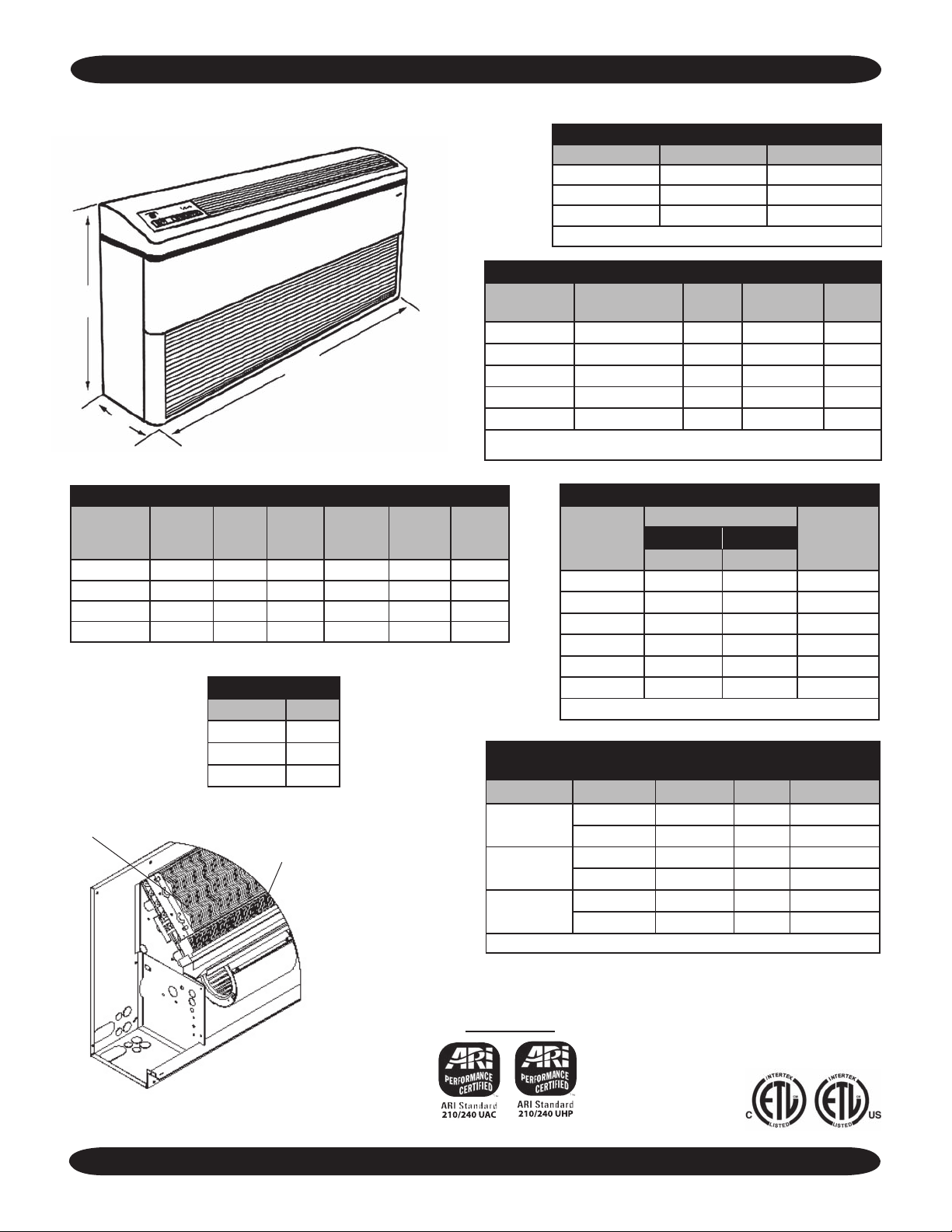
(FCP/FHP) DIMENSIONS AND SPECIFICATIONS Continued
NOTE: Due to EMI’s ongoing development programs, designs and specifications may change without notice.
FCP/FHP FRESH AIR SPECIFICATIONS*
Model # Total CFM Outside Air CFM
9/12, 15 440 50
18/24, 30 725 75
36/42, 48 1200 160
* Open or Motorized Damper
FCP/FHP ELECTRICAL SPECIFICATIONS
26”
101/2”
47” (09-30), 611/2” (36-48)
Model # Voltage/Hz/Ph
Fan
FLA
9/12A 115/60/1 1.5 1.9 15
9/12, 15 208-230/60/1 0.6 0.8 15
18/24 208-230/60/1 0.8 1 15
30 208-230/60/1 1.1 1.4 15
**36/42, 48 208-230/60/1 1.1/1.1 2.5 15
* If electric heat is installed, use data from FHP Electric Heat Specifications table.
** 36 requires piston kit #550-121 (see pg 5)
Min.
Ampacity*
Max.
Fuse*
FCP/FHP ELECTRICAL HEAT SPECIFICATIONS
Model# Voltage KW
9/12, 15 230 3 13.1 13.7 17.1 20
18/24 230 5 21.7 22.7 28.2 30
30 230 5 21.7 22.8 28.6 30
36/42, 48 230 7 30.4 32.6 40.6 45
Heater
Amps
Total
Amps
Min.
Circuit
Amps
FHP SHIPPING WT.
Model# LBS.
9/12, 15 110
18/24, 30 120
36/42, 48 165
Hydronic Coil
Evaporator Coil
FHP PIPING SPECIFICATIONS
Max.
Fuse
Amps
Model#
Refrigerant Line Size
Flare* Flare*
9/12 1/4” 1/2” 1/2” I.D.
15 1/4” 5/8” 1/2” I.D.
18 3/8” 5/8” 5/8” I.D.
24 3/8” 3/4” 5/8” I.D.
30 3/8” 3/4” 5/8” I.D.
36/42, 48 3/8” 3/4” 5/8” I.D.
* Flare fittings NOTE: Flare nuts not included.
FCP/FHP HYDRONIC HEAT SPECIFICATIONS
(Single-stage Heating only)
Model# EWT °F Btuh GPM PD Ft. H2O
9/12, 15
18/24, 30
36/42, 48
NOTE: Not available with Heat Pump applications.
180 24,300 2.0 3.4
140 18,400 2.0 3.4
180 41,500 3.5 5.6
140 26,200 3.5 5.6
180 39,500 6.0 8.8
140 62,400 6.0 8.8
Drain HoseLiquid Suction
Hydronic Coil
Location
The Ductless Split System of Choice
FHP’s ONLY
11
www.enviromaster.com
Page 12
(FCP/FHP) DIMENSIONS AND SPECIFICATIONS Continued
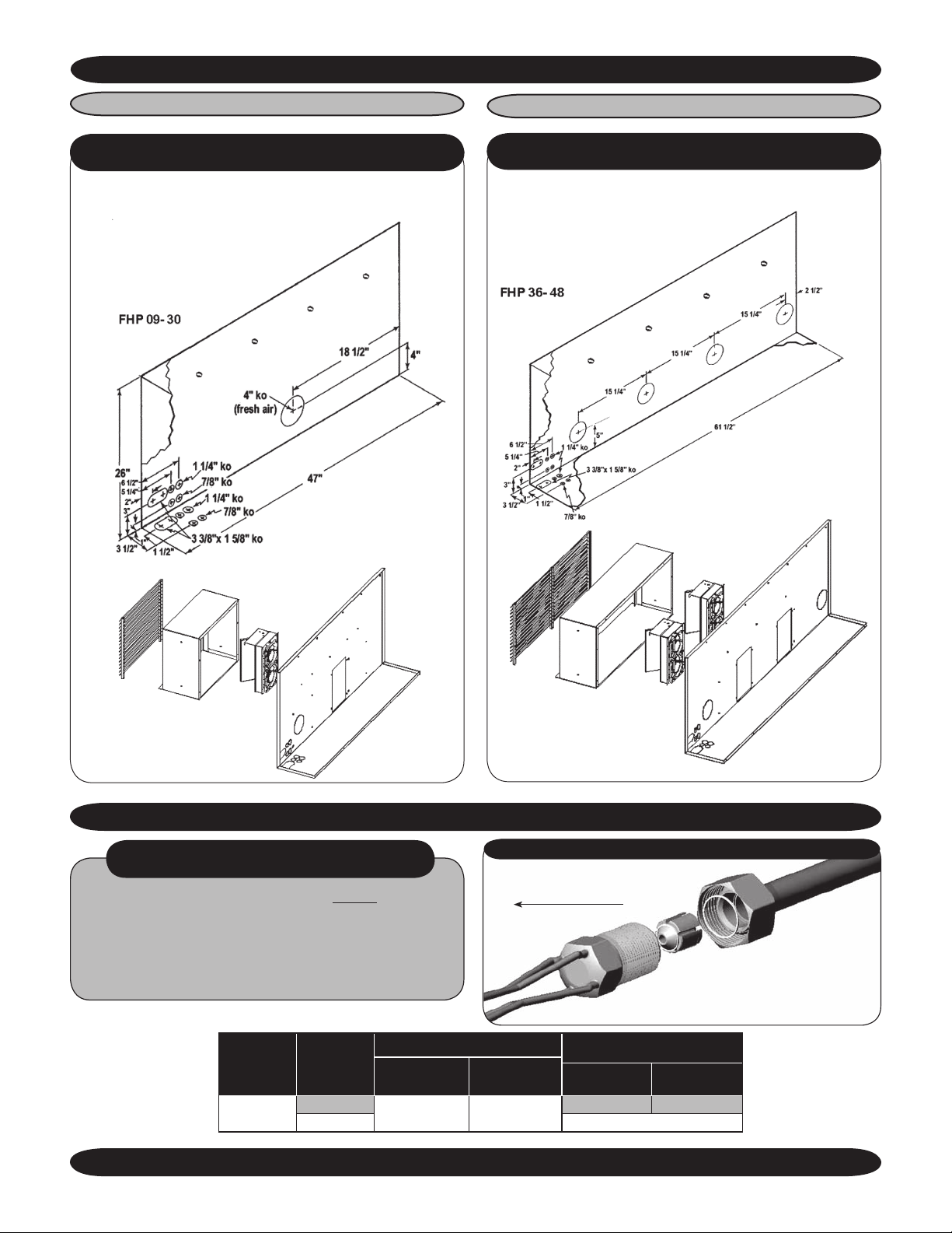
Connection K.O.s for Open Fresh Air
FHP 09- 30 Motorized Damper and
Power Assisted Fresh Air (2 Fan Type)
Wall Box Dimensions: 14”
(from finished floor level) x 17” wide x 8” deep
Lagging holes positioned 8” on center for optional mounting
FHP 36- 48 Motorized Damper and
Power Assisted Fresh Air (4 Fan Type)
Wall Box Dimensions: 14”
(from finished floor level) x 32” wide x 8” deep
FIELD INSTALLATION INSTRUCTION CHP12 PISTON/ORIFICE
APPLIES TO CHP 9,000 BTUH - 12,000 BTUH
NOTE: Replace the existing piston (before installing
the unit) with the piston supplied in Kit Bag when
matching a:
• CHP12 with 9,000 Btuh Condenser
Made in Rome, New York, USA
Built After 4/05
(See chart below)
Model #
Air Handler
CHP12
Condenser
Btuh
9,000
12,000
Factory Installed
Part #
Piston/Orifice
240004064 .044”
PROPER INSTALLATION OF PISTON/ORIFICE REPLACEMENT
Evaporator
Field Changeover
Piston/Orifice
Size
12
Part #
Piston/Orifice
240000727 .041”
Piston/Orifice
NO CHANGE
E-mail: [email protected]
Size
Page 13
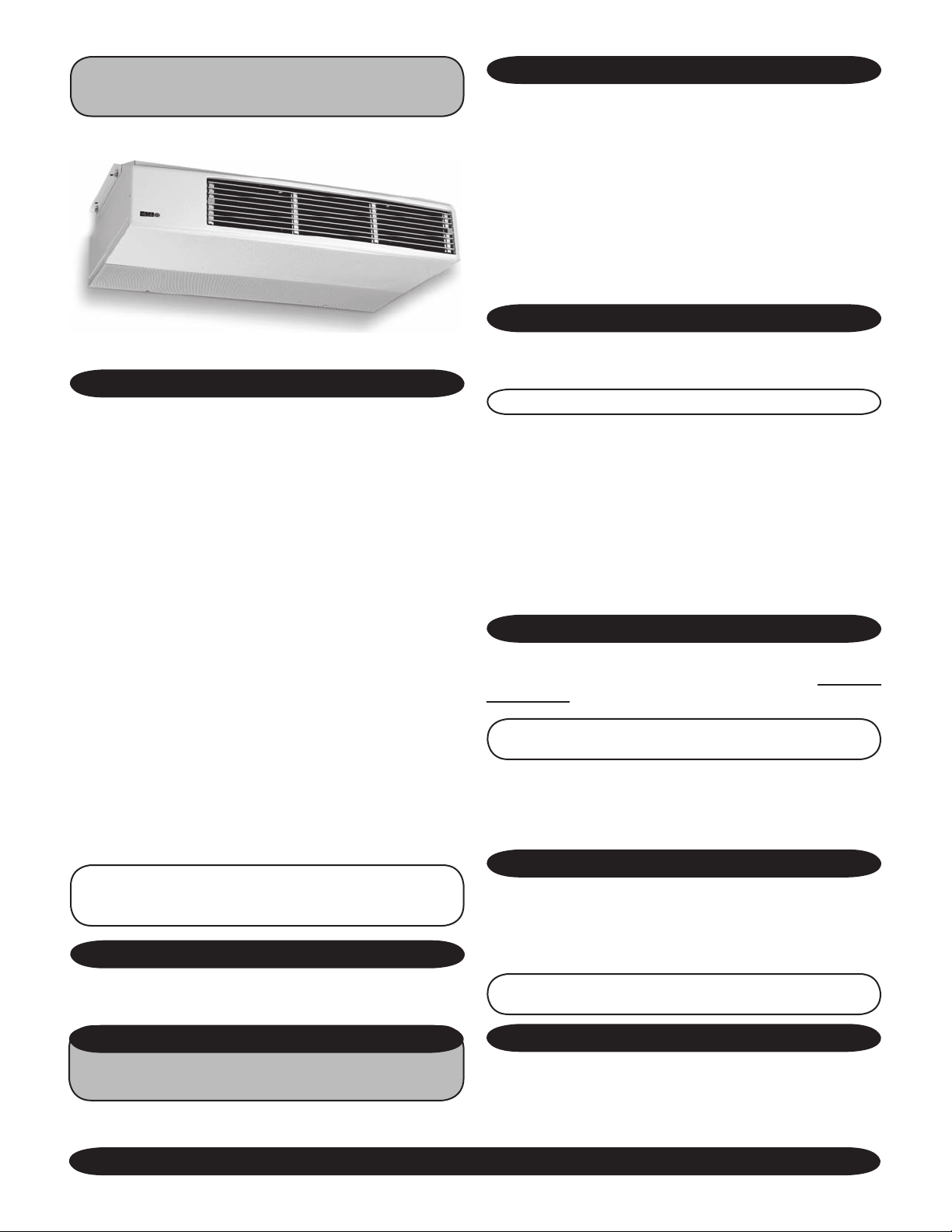
CEILING MOUNTED AIR HANDLER
CHP
DESCRIPTION
The EMI CHP is a highly effective ceiling mounted evaporator
for applications where fully exposed or partially recessed cabinetry
can be used. For partially recessed mounting, these units easily
adapt to standard T-bar, drop-ceiling openings. The CCP/CHP is
designed for residential and commercial applications where the
unit may be concealed in soffits or other structural spaces with
only the intake and discharge grilles exposed. When concealing
the unit make provisions to the soffit for future access to the unit
for maintenance purposes. When offering the Infraoption, due to the fact that the infra-red receiver is located on
the unit, the CHP model cannot be mounted in a soffit or another
structural space.
The aluminum supply air louvers are dual adjustable for air
flow direction, to provide air flow throws to suit any installation.
The louvers are mounted in a high impact polystyrene front sec
tion. The CHP incorporates dual blowers that produce efficient,
quiet operation, suitable for both residential and commercial
applications. A wide range of options are available for the CHP
units, including supplemental electric or hydronic heat options,
a factory or field installed condensate pump, and optional digital
and hand held IR remote controls.
The CHP models are fast and easy to install with 24V control
circuits to the outside unit, standard. Hanger brackets and fresh
air openings are standard on all models. Optional trim kits are
available for surface mounting applications.
NOTE: If equipped with hydronic heat, the CHP will
only operate as a single-stage heating unit and not as
a two-stage heating unit.
ITEM FOR CONSIDERATION
Red Control
MOUNTING PREPARATION
Choose the best location for the unit. Use the cardboard template
(provided with unit packing) to “test fit” the unit before installation
1. The CHP Series is designed to be mounted to a horizontal
surface which should be plumb and level.
2. Using the template, mark a spot where the piping should
penetrate the wall.
3. Determine appropriate hole size and cut through the
mounting surface.
Piping for new construction can be roughed in before wallboard or
panels are put in place. PVC pipe may be used as a pipe chase.
MOUNTING
1. Remove access panel, attach the front panel and louvers
to the chassis section with supplied nuts.
NOTE:
Front panel shipped separately in cartoning.
2. Secure the unit to the ceiling using appropriate hardware
(screws for wood, anchors for masonry).
3. The CHP unit can be ceiling suspended using threaded rods
and double nuts to ensure fasteners won’t loosen.
4. Pitch the unit slightly towards the drain for proper conden
sate removal.
5. Run power wiring and refrigerant lines into the unit.
REFRIGERANT PIPING
CHP units are equipped with a piston flow regulator expansion
device. Piping connections are standard flare type
not included).
NOTE: See specifications for line sizing and actual unit
connections.
1. Be certain there are no burrs on either side of the tubing.
2. The large line (suction) should be insulated with closed cell
foam tube insulation. Do not insulate the small liquid line.
(flare nuts
PIPING DO’S AND DON’TS
• Avoid piping on a rainy day.
• Use refrigerant grade copper tubing.
• Use a tubing bender and avoid unnecessary bending.
• Cap ends of lines until ready for final connections.
• Install a P-trap for every 10’ of vertical rise.
-
Ensure that the CHP interconnect tubing is within a maximum
allowable length of 100’ including, a maximum 35’ lift.
OPTIONAL CONTROLS & COMPONENTS
See page 4 in Common Section for
complet list of Optional Controls/Components
The Ductless Split System of Choice
NOTE: Connections to outdoor sections should be made
according to the outdoor section installation instructions.
FRESH AIR
This is a 4” round knockout and will accept a 4” round duct.
Dampers, wall collars, and outdoor grilles are field supplied. Do
not allow moisture or other foreign matter to enter through the fresh
air intake. When ducting, pitch slightly to the outside to prevent
moisture from entering the chassis.
13
www.enviromaster.com
Page 14
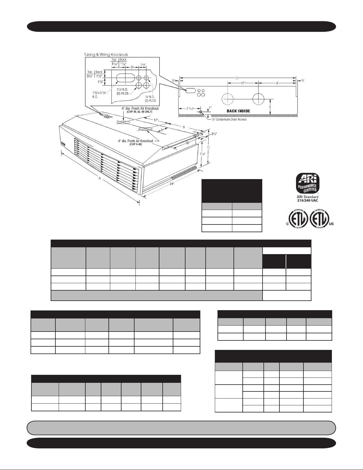
CHP DIMENSIONS AND SPECIFICATIONS Continued
NOTE: Due to ongoing development programs, design and specifications may change without notice.
CHP OBSERVED
SOUND LEVELS
(230V Low Speed Fan)
Model# dBA
12 46.3
18 50.8
24 56.0
CHP PHYSICAL DIMENSIONS AND PIPING SPECIFICATIONS
Model#
12 42” 16½” 10¾” 41” 5½” 1/2” I.D. 115 1/4” 1/2”
18 49” 19” 10¾” 48” 5½” 5/8” I.D. 135 3/8” 5/8”
24 49” 19” 10¾” 48” 5½” 5/8” I.D 135 3/8” 3/4”
Width
“A”
Width
“B”
Width
“C”
Width
“D”
Width
“E”
Drain
Hose
Shipping
Wt.
Ref. Line Sizes
Liquid
(Flare)
Flare nuts not
included
Suction
(Flare)
CHP ELECTRICAL SPECIFICATIONS
Model# Voltage Hertz Fan FLA
Min.
Ampacity *(1)
12 115 60 1.4 1.8 15
12 208/230 60 0.6 0.8 15
18/24 208/230 60 1.1 1.4 15
*(1) If electric heaters are installed, use Min Amp and Max Fuse from
Heater Options Chart.
CHP WITH ELECTRIC HEAT OPTIONS
Total
Model# Voltage KW
Htr
Amps
Amps
Min. Cir.
Amps
Max.
Fuse
12 208/230 3 13.1 13.7 17.1 20
18/24 208/230 5 21.7 22.8 28.6 30
NOTE: Please refer to the Common section in the front of this manual for detailed instructions on:
Controls/Components, Electrical Wiring, Start-Up, and more.
Made in Rome, New York, USA
Max.
Fuse *(1)
14
CHP DISCHARGE AIR SPEED AND THROW
Model# CFM Coil FPM Throw/Ft.
12 350 Dry 290 12.4
18/24 800 Dry 533 18.6
CHP HYDRONIC HEAT SPECIFICATIONS
(Single-stage Heating Only)
Model# EWT °F GPM Btuh PD Ft. H2O
12
18
24
140 2 14,500 3.4
180 2 22,900 3.4
140 4 27,200 5.2
180 4 43,200 5.2
140 4 29,800 5.2
180 4 47,300 5.2
E-mail: [email protected]
Page 15
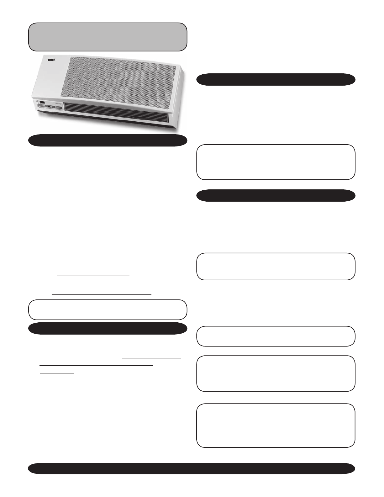
WALL MOUNTED AIR HANDLER
(WCP/WHP)
PRODUCT DESCRIPTION
The WHP is a ductless type evaporator, while the WCP
is a chilled water air handler, both have a contemporary
design with an attractive appearance to fit any décor. They
offer high efficiency conditioning of small to mid-size commercial or residential spaces. The WHP/WCP is equipped
with unit mounted infrared compatible controls; an optional
hand held remote is available.
WHP/Heat Pump models provide up to a nominal
33,000 Btuh of cooling and 36,000 Btuh of heating. Electric
heat options are available for up to 5KW of supplemental
heat. The WCP/Chilled Water models provide up to a
nominal 30,000 Btuh of cooling. Electric Heat options are
available for up to 5KW of supplemental heat. It can be
paired with a matching capacity chilled water source unit.
Check page 3 in common section of this manual for
a list of Controls and Components .
Check page 6 in common section of this manual for a
list of Optional Controls and Components .
NOTE: Unit mounted controls are fully functional
without the remote.
ITEMS FOR CONSIDERATION
• Check equipment for damage prior to installation. A
foam block has been placed under the blower wheel
to prevent shipping damage. Be sure to remove
the foam block before starting the unit.
• WHP’s Only (Not WCP’s) Depending on condenser
capacity rating in Btuh, the factory installed piston
orifice expansion device may need to be changed
out with the one in the kit bag supplied with the WHP
unit (instructions are included).
• Determine the best location for mounting the unit
and room air circulation. Locate outdoor and indoor
units as close together as possible.
• Determine how refrigerant and power line may be
run to and from unit.
• Determine if the cabinet front can be removed without obstruction.
• Ensure that the WHP interconnect tubing is within
a maximum allowable length of 100’ including, a
maximum 35’ lift.
• EMI’s WHP evaporator requires 24V power for
control operation. (As of 12/01/04 a transformer is
supplied in the indoor unit).
MOUNTING PREPARATION
The WHP/WCP must be mounted plumb and level to
a vertically square surface to prevent unit vibration and/or
unwanted noise. It is recommended that the WHP be
mounted directly to a smooth surface or sheetrock wallboard or similar material. If mounting to a block wall, there
should be a smooth square backing between the unit and
the block surface to absorb any potential vibration.
NOTE: If excessive noise or vibration is experienced from a unit mounted directly to a block wall,
the squareness of the wall should be checked
immediately.
UNIT MOUNTING
1. After determining the best location for the unit, use the
cardboard template provided in the packaging.
2. Mark the spot where the piping should penetrate the
wall.
3. Determine the appropriate hole size and cut through
the wall.
NOTE: Piping may be roughed in before wallboard
or panels are placed in new construction. PVC pipe
(3” or 4” I.D.) may be used as a pipe chase.
4. Use the supplied wall bracket. Secure the bracket to
the wall with the appropriate screws (for wood) or anchors
(for masonry).
5. Mount the unit to the bracket and make certain it fits
properly.
NOTE: The wall hanging bracket slot is NOT located
in the center of the unit.
NOTE: Panels should remain on the unit at all
times. Service should be performed by a QUALI
FIED service agency. An annual system check by
a qualified service technician is recommended.
NOTE: Please refer to the Common section in the
front of this manual for more detailes on: Controls/Components , Electrical Wiring (pgs 4-7),
Start-Up, Operation and Cleaning & Maintenance
(pgs 18-27).
-
The Ductless Split System of Choice
15
www.enviromaster.com
Page 16
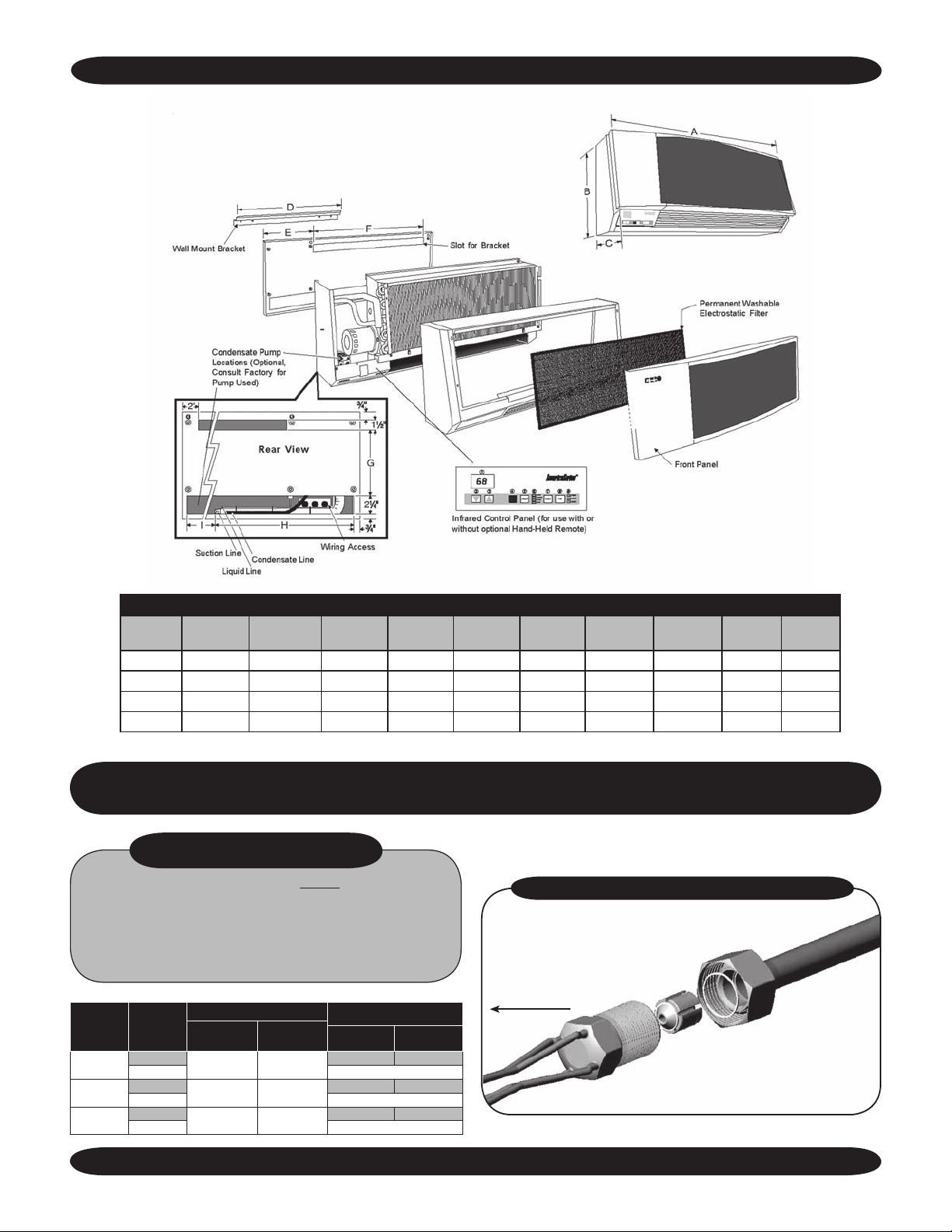
(WCP/WHP) DIMENSIONS AND SPECIFICATIONS
NOTE: Due to ongoing development programs, design and specifications may change without notice.
WCP/WHP PHYSICAL DIMENSIONS
Model Width “A” Height “B” Depth “C” Width “D” Width “E” Width “F” Width “G” Width “H” Width “I”
09/12 36½” 14½” 10¾” 22” 9” 24½” 8” 18” 16” 85
15/18 47½” 14½” 10¾” 32” 10” 34½” 8” 18” 27” 115
24/30 57½” 14½” 10¾” 42” 10” 44½” 8” 27” 28” 115
36 57½” 17” 11¼” 42” 10” 44½” 10½” 25” 28½” 115
FIELD INSTALLATION INSTRUCTION
WHP12/18/30 PISTON/ORIFICE
APPLIES TO WHP 9,000 Btuh -
30,000 Btuh BUILT AFTER 4/05
NOTE: Replace the existing piston (before installing the unit)
with the piston supplied in Kit Bag when matching a:
• WHP12 with 9,000 Btuh Condenser
• WHP18 with 15,000 Btuh Condenser
Model #
Air Handler
WHP12
WHP18
WHP30
• WHP30 with 24,000 Btuh Condenser
(See chart below)
Condenser
Btuh
9,000
12,000
15,000
18,000
24,000
30,000
Factory Installed
Part #
Piston/Orifice
240-4064 .044”
240-4111
240-2089 .063”
Piston/Orifice
Size
.053”
Field Replacement
Part #
Piston/Orifice
240-727 .041”
NO CHANGE
240-1010 .049”
NO CHANGE
240-3961 .059”
NO CHANGE
Piston/Orifice
Size
Shipping
Wt.
PROPER INSTALLATION OF PISTON/ORIFICE REPLACE
Evaporator
MENT
Made in Rome, New York, USA
16
E-mail: [email protected]
Page 17
(WCP/WHP) DIMENSIONS AND SPECIFICATIONS
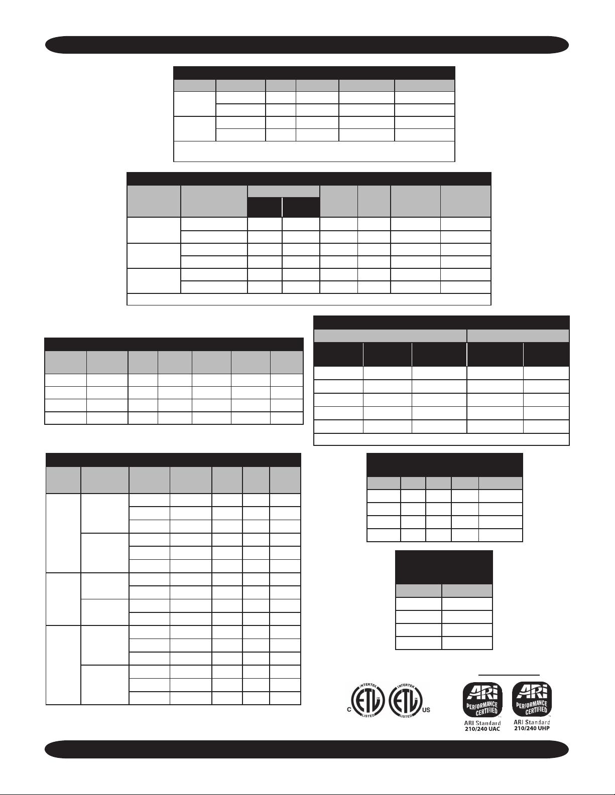
WHP ELECTRICAL SPECIFICATIONS
Model Voltage Hertz Fan FLA Min Amp (1) Max Fuse (1)
9/12
15-36
(1) If electric heaters are installed, use Min Amp and Max Fuse from Heater
Options Chart.
Model # Volts/HZ/Phase
09/12
15/18
24/30
(1) If electric heaters are installed, use Min Amp and Max Fuse from Heater Options Chart.
WCP/WHP ELECTRIC HEAT OPTIONS
Model Voltage KW
9/12 230 3 13.1 13.5 16.8 20
15/18 230 3 13.1 13.6 17 20
24/30 230 5 21.7 22.3 27.9 30
36 230 5 21.7 22.3 27.9 30
Heater
Amps
115/60/1
208/230/60/1 0.34 0.02 0.34 197 0.43 15
115/60/1
208/230/60/1 0.56 0.07 0.56 197 0.7 15
115/60/1
208/230/60/1 0.56 0.07 0.56 197 0.7 15
Total
Amps
115
208/230 60 0.34 0.43 15
115
208/230 60 0.56 0.7 15
WCP ELECTRICAL SPECIFICATIONS
Min. Cir.
Amps
60 0.7 0.8 15
60 1.2 1.5 15
Fan
FLA HP
0.64 0.03 0.64 104 0.8 15
1.2 0.083 1.2 104 1.5 15
1.2 0.083 1.2 104 1.5 15
Max
Fuse
Total
Amps
Min.
Volt
Min.
Ampacity
(1)
Max
Fuse (1)
CONNECTIONS
WHP/Refrigerent Line Size WCP
Model Liquid Suction
Chilled Line
Size
Drain
Size
9/12 1/4” 1/2” O.D. 1/2” I.D. 1/2” I.D.
15 1/4” 5/8” O.D. 5/8” I.D. 1/2” I.D.
18 3/8” 5/8” O.D. 5/8” I.D. 1/2” I.D.
24/30 3/8” 3/4” O.D. 3/4” I.D. 1/2” I.D.
36 3/8” 7/8” O.D.* - 1/2” I.D.
* WHP Suction Connection is 3/4” O.D. and must be bushed down at the WHP Unit.
WCP CAPACITIES
Model
Nominal
Capacaties
Total
Capacity
Sensible
Capacity
7,375 6,732 45 1 0.8
9,000
09/12
12,000
10,801 8,272 45 2 3.8
13,270 9,279 45 3 8.0
8,387 7,189 40 1 0.8
12,481 8,950 40 2 3.9
15,643 10,304 40 3 8.1
15,000
15 /18
18,000
15,624 13,477 45 2 4.4
19,761 15,367 45 3 9.1
17,724 14,379 40 2 4.5
23,073 16,763 40 3 9.3
20,563 17,564 45 3 2.3
24,000
24/30
30,000
29,031 21,178 45 6 8.3
32,320 22,539 45 9 17.7
23,600 18,887 40 3 2.4
34,400 23,423 40 6 8.4
38,790 25,351 40 9 17.9
The Ductless Split System of Choice
Fluid
Temp.
Fluid
Flow
PD
Ft. H20
17
DISCHARGE AIR SPEED AND FLOW
(230V High Speed Fan)
Model CFM Coil FPM Throw/Ft.
9/12 310 Dry 960 16
15/18 600 Dry 1412 26
24/30 750 Dry 1400 25
36 750 Dry 1400 25
WCP/WHP OBSERVED
SOUND VALUES
(230V High Speed Fan)
Model DbA
9/12 48
15/18 51
24/30 54
36 54
WHP’s ONLY
www.enviromaster.com
Page 18
COMMON TO ALL AIR HANDLERS Continued from page 7
PREPARATION FOR START UP
See the “Common” section of this manual (on pages
18-22) for control details.
• Confirm that the dip switch settings are correct for
your unit (Figure 4)
• Remove any tools or other obstructions
• Be sure the filter is in place
• Verify that the unit is level
• Separate any lines that contact each other
• Replace the cabinet front onto the chassis
Test each power and circuit connection before powering
up the system. Use the unit mounted electronic thermostat
controls to start the system. (See pages 18-23 for
ing Instructions on Control Operation Section, Thermostat,
Unit Mount or Remote.)
NOTE: Check the outdoor unit’s start-up instructions for specific requirements and procedures.
Operation of the unit depends on the room temperature.
It may be necessary to warm the room before testing the
unit’s cooling abilities.
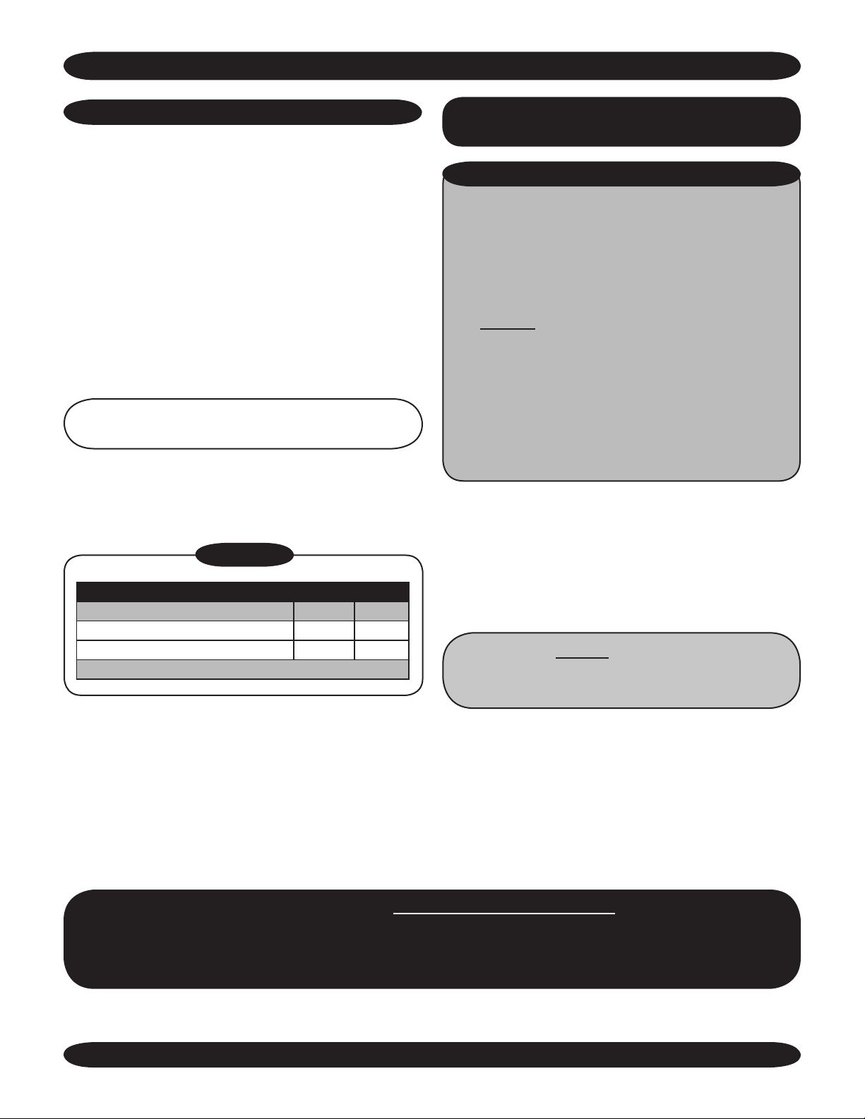
Figure 4
DIP SWITCH SETTINGS
Switch 1 2
Cooling only Open Open
Cooling Electric or Hydronic Heat On On
Off = Open On = 1 or 2
Operat-
INITIAL START-UP
Unit Mount Controls Only
UNIT MOUNT INFRARED CONTROL OPERATION
EMI Air Handlers are equipped with a unit mount,
infrared compatible control package (optional on the
CCP/CHP). This user friendly, microprocessor control is
designed to optimize system performance and protect
the refrigeration system from unwanted short cycling
and evaporator freeze-ups. Operation of the unit can be
made by either the keypad on the unit or by using
the optional hand held infrared controller.
There are two dipswitches on the relay board that of
fer different modes of operation. This allows the unit
to be matched with either a cooling only or heat pump
condenser. Dipswitches are factory set for a cooling
only condenser. If the indoor unit is matched with an
EMI single zone or multi-zone heat pump condenser,
the dipswitches will need to be changed.
The unit will start in time delay. These are the default
settings of the unit mount I/R control microprocessor. Once
temperature and mode selections have been made, they
will be stored in the microprocessor memory when the unit
is switched off. The next time the unit is switched back on
via the On/Off switch, the stored settings will be used and
the unit will resume operation.
Refer to the specific model of Air Handler for
more detailed installation instructions. (Pages
8-12)
-
After starting the unit, complete the Test Unit Performance Data sheet on page 23.
Save this information for future servicing. In the event there is a problem with the unit.
Perform the test again (if possible) and have both sets of data ready when
calling for assistance.
Made in Rome, New York, USA
18
E-mail: [email protected]
Page 19
COMMON TO ALL AIR HANDLERS - SEQUENCE OF OPERATION Continued
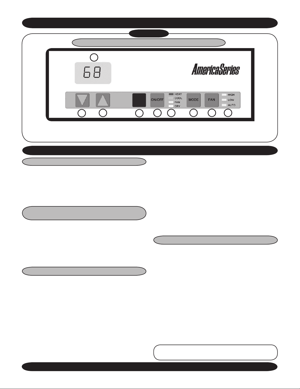
Figure 5
UNIT MOUNTED INFRARED COMPATIBLE CONTROL
1
2
1. LCD Display
2. Temp. Set Point Down Button
3. Temp. Set Point Up Button
3
4. Infrared Sensor
5. Power ON/OFF Button
6. Mode Indicator LEDs (HEAT, COOL, FAN, DRY)
4
START-UP FOR UNIT MOUNTED INFRARED COMPATIBLE CONTROL (Only)
ON/OFF SWITCH
The On/Off switch is used to turn the equipment on or
off. In the off mode the display will be blank and all LED
indicator lights will be dark. To turn on the unit press the
On/off button once. Room temperature will be displayed
and amber LED indicators will show fan speed and mode
selections (Figure 5).
MODE SWITCH
(System Switch)
The Mode button will allow the selection of the desired
mode of operation. Colored LED indicators will light next
to the selected mode. With each successive press of the
Mode button, selection will rotate between Heat, Cool,
Fan or Dry mode. If the dipswitches are set for cooling
only (off
– off) then Heat and Dry will not be accessible
(Figure 5).
FAN OPERATION
The indoor unit utilizes a two-speed motor with three
operational fan modes. The Fan button will allow the selec-
tion of the desired fan setting. An amber LED indicator will
light next to the fan speed selection. If Auto fan mode is
selected then an LED indicator will also light next to Auto.
High and Low are constant fan settings. The fan will
operate continuous regardless of set point or room temperatures. Auto mode is a cycling fan setting.
Auto fan mode can only be selected if the unit is in
Heat or Cool mode. In Auto mode the fan will cycle with
the call for Heat or Cool. Fan speed will be determined by
the microprocessor and speed adjustment will be made
according to room and setpoint temperatures. The fan will
switch to High speed when room temperature deviates by
5
6
7
7. Mode Selection Button
8. Fan Operation Button
9. Fan Indicator LEDs (HIGH, LOW, AUTO)
8
9
more than two degrees from setpoint. The fan will switch
to low speed if the deviation is one degree. When the room
temperature reaches setpoint temperature the heat/cool call
will then be dropped. The fan will stay on for an additional
60 sec. to purge unit of any residual energy. After the fan
has been off for ten minutes, the fan will cycle on for 60
seconds. This is done so the microprocessor can sample
the room air and also helps eliminate room temperature
stratification.
When the unit is in
constant at low speed. While the unit is in Fan mode,
Dry mode the fan speed will remain
Auto
is bypassed and only High or Low are available (Figure 5).
COOLING ONLY OPERATION
For cooling operation first turn the unit on via the On/off
button. Select Cool mode via the Mode button. The room
temperature will be displayed. Then, by depressing either
the Up or Down arrow once, the setpoint temperature will
appear. The setpoint temperature can then be changed with
each successive press of the Up or Down arrow buttons
or by holding the button in. Place the setpoint temperature
below the room temperature. The compressor will start and
cooling will continue for a minimum of two minutes and as
long as the setpoint remains below room temperature. (On
initial startup or if power is lost, there is a three-minute delay
between compressor re-starts.)
Once the room temperature is satisfied and the twominute minimum run time has elapsed the compressor will
cycle off. The fan will operate as described in “Fan Operation” (Figure 5).
NOTE: Once the compressor is switched off there
is a three-minute delay before it will re-start.
The Ductless Split System of Choice
19
www.enviromaster.com
Page 20

COMMON TO ALL AIR HANDLERS - SEQUENCE OF OPERATION Continued
OPTIONAL ELECTRIC HEAT OPERATION
(Non Heat Pump Condenser Units Only)
Important: The dip switch 1& 2 must be set to ON
For electric heat operation first turn the unit on via the
On/Off button. Select Heat mode via the Mode button. The
room temperature will be displayed. Then by depressing
either the Up or Down arrow once, the setpoint temperature
will appear. The setpoint temperature can then be changed
with each successive press of the Up or Down arrow or
by holding the button in. Place the setpoint temperature
above room temperature. The electric heat will energize
and heating will continue as long as the setpoint remains
above room temperature. Once the room temperature is
satisfied the electric heat will cycle off. The fan will operate
as described in “Fan Operation” (Figure 5).
OPTIONAL HEATPUMP WITH
ELECTRIC HEAT
Important: The dip switch 1=OFF/Open
The dip switch 2=ON/2
For heat pump operation with backup electric heat, first
turn the unit on via the On/off button. Select Heat mode via
the Mode button. The room temperature will be displayed.
Then, by depressing either the Up or Down arrow once, the
setpoint temperature will appear. The setpoint temperature
can then be changed with each successive press of the Up
or Down arrow or by holding the button in.
Place the setpoint temperature one-degree above the
room temperature. The compressor will start and heating
will continue for a minimum of two minutes and as long as
the setpoint remains above room temperature. Once the
room temperature is satisfied and the two-minute minimum
run time has elapsed, the compressor will cycle off.
(*) On initial startup (or if power is lost) there is a three-
minute delay between compressor re-starts.
(**) Some EMI Heat pump condensers are equipped
with a low temperature cutout that will shut down the con
denser and energize the indoor heat. This is designed to
protect the compressor under certain outdoor conditions.
(***) Some EMI Heat pump condensers energize the
indoor unit electric heat during defrost.
Next, place the setpoint temperature at least two
degrees above room temperature. The electric heat will
energize along with the compressor (heatpump) thus twostage heating. The electric heat will continue to run until the
deviation between room temperature and setpoint tempera
ture is less than two degrees. At that time the electric heat
will switch off and the heatpump will take over the heating
demand. Once the room temperature is satisfied and the
two-minute minimum run time has elapsed, the compressor
Made in Rome, New York, USA
(2-Stage Heating)
will cycle off. There is then a three-minute delay before the
compressor can restart. The fan will operate as described
in “Fan Operation” (Figure 5).
DRY MODE OPERATION
Dry mode will remove humidity from the air while
maintaining a specific setpoint temperature. This is done
by energizing the compressor in cooling along with the electric or hydronic heater. Dry mode will not maintain a specific
humidity level. The unit must be equipped with an optional
electric heat element or hydronic coil.
For Dry Mode operation first turn the unit on via the On/
off button. Select Dry mode via the Mode button. The room
temperature will be displayed. Then by depressing either the
Up or Down arrow once, the setpoint temperature will appear.
The setpoint temperature can then be changed with each
successive press of the Up or Down arrow or by holding the
button in.
Place the setpoint temperature at a desired room temperature. Depending on the difference between room temperature
and set point temperature the compressor and/or heat source
will energize. If the room temperature and setpoint temperature
are the same the compressor will operate in cooling and the
electric heat source will also energize.
Should the room temperature fall below the setpoint
temperature by two degrees, the compressor will stop and
heating will continue to boost the room temperature back up
to stepoint temperature. If the room temperature rises above
the setpoint temperature by two degrees, heating will stop and
cooling will continue to bring the room temperature back down
to stepoint temperature. The fan will operate continuously at
low speed while in Dry Mode.
In order to prevent short cycling the minimum on time for
both cooling and heating is two minutes. The minimum off
time is 3 minutes (Figure 5).
UNITS WITH CONDENSATE PUMPS
EMI Air Handlers are available with an optional con-
densate pump. Condensate pumps are recommended
-
when it is not possible to gravity drain the condensation
from the indoor unit. Depending on the pump manufacture
the maximum lift for the pump will vary. Consult the pump
instructions for the maximum lift for the particular pump
being used or refer to specific pump kit information and
instructions as supplied by EMI.
Condensation generated by the evaporator will col-
lect in the pumps’ reservoir. When the water level is high
enough, a float switch will close and energize the pump
motor clearing the water from the reservoir. Should for
any reason the water exceed the maximum preset level,
a safety switch will open, there by interrupting the (Y) signal to the condenser. This will prevent the evaporator from
generating more condensation and spilling out of the unit.
20
E-mail: [email protected]
Page 21
COMMON TO ALL AIR HANDLERS - SEQUENCE OF OPERATION Continued
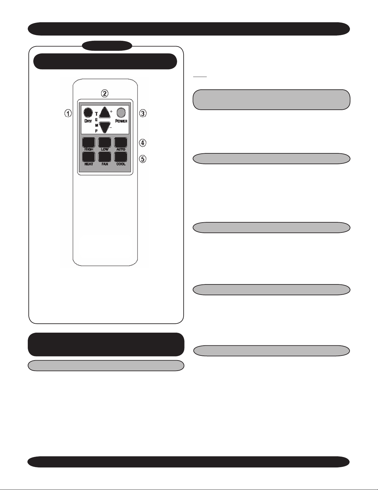
Figure 6
INFRARED REMOTE CONTROL OPTION
OPERATIONAL RANGE 55- 90° F (IN 1° INCREMENTS.)
When selecting a thermostat other than those offered
by EMI, it is important to choose a 24V thermostat that
matches your application. EMI equipment is compatible with
most mercury bulb, digital or power stealing thermostats.
COOLING ONLY WITH ELECTRIC HEAT OR
HYDRONIC HEAT
Select a thermostat that is compatible with a cooling
- electric heat system. The thermostat should have “R”, “Y”,
“W” and “G” terminals. The thermostat may also have a “C”
terminal.
HEAT PUMP WITH ELECTRIC HEAT
Select a thermostat that is compatible with a singlestage cooling, two-stage heat, heat pump system. The
thermostat should have “R”, “Y”, “O”, “W (or W2)” and “G”
terminals. The thermostat may also have a “C” terminal. If
the indoor unit is not equipped with electric or hydronic heat
then a single stage heat pump thermostat is adequate.
1. Dry Mode Button
2. Temp. Set Point UP/DOWN Button
3.Power ON/OFF Button
4. Fan Speed Button (HIGH, LOW, AUTO)
5. Operational Mode Buttons (HEAT, FAN COOL)
NOTE: Batteries Included.
START - UP FOR
WALL THERMOSTAT CONTROL
CHOOSING A THERMOSTAT
EMI offers several remote thermostats that are compatible with the Ductless split system air handlers. See the
latest price list for a list of available thermostats. It is important to choose a thermostat that will match the equipment
that you have selected. For single stage cooling or heating
choose a single stage Heat/Cool thermostat. If you have
selected an outdoor heat pump unit and an indoor unit with
electric heat then chose a two-stage heating, single-stage
cooling thermostat.
FAN OPERATION
Some thermostats are equipped with an auto/on fan
switch. When this switch is placed in the on position the
indoor fan will run continuous. When the switch is in the
auto position the indoor fan will cycle with the call for heating or cooling.
FAN PURGE
The indoor unit is equipped an electronic circuit board
with a purge feature. After the room thermostat has been
satisfied, the purge feature allows the indoor fan to remain
on for an additional 60 seconds. This increases efficiency
by pulling the remaining energy from the unit.
COOLING OPERATION
The electronic circuit board of the indoor unit also has
an anti-short cycle timer (ASCT) feature designed to protect
the compressor from short cycling. The ASCT is activated
immediately following the off cycle of the outdoor unit. Once
the room temperature is satisfied and the outdoor unit
switches off, the ASCT will not allow the outdoor to restart
unit a three-minute time period has elapsed.
The Ductless Split System of Choice
21
www.enviromaster.com
Page 22

COMMON TO ALL AIR HANDLERS - SEQUENCE OF OPERATION Continued
After connecting the thermostat to the unit place the
system switch in cool mode. Adjust the set-point temperature below the room temperature. The compressor
and fan motors will start and cooling will begin. For chilled
water systems, the coldwater valve will open allowing the
flow of water. Place the set-point temperature above the
room temperature. The outdoor condenser will stop (or CW
valve will close) while the indoor fan will remain on for an
additional sixty seconds.
ELECTRIC HEAT OPERATION
Place the thermostat system switch in heat mode
Adjust the set-point temperature above the room temperature. The electric heat will energize along with the indoor
fan motor. Heating will continue so long as the set-point
remains above room temperature. Next place the set-point
temperature below room temperature. The electric heater
will switch off and the indoor fan will remain on for an additional sixty seconds.
HYDRONIC HEAT OPERATION
(Optional On CHP And FHP Units)
An optional hydronic heat package may be selected
in lieu of electric heat. Heating operation is essentially the
same as that of units with electric heat. With the thermostat
system switch set to heat and the set-point temperature
above room temperature, the hydronic valve will open allowing water to flow through the coil. The indoor fan will
also switch on and warm air will flow from the unit. Heating
will continue so long as the set-point remains above room
temperature. Place the set-point temperature below room
temperature. The hydronic valve will close and indoor
fan will switch off after the sixty-second purge time has
elapsed.
Units with an optional hydronic heat coil or chilled water
coil are also equipped with a freeze protection thermostat.
The freeze protection thermostat is designed to protect
the hydronic coil or chilled water coil from freeze up due
to abnormally cold fresh air from the fresh air system or
from abnormally cold air from the evaporator coil. Should
the freeze sensor activate, the indoor fan will switch off to
eliminate the source of cold fresh air, and also the outdoor
condensing unit will be switched off eliminating cold air
from the refrigeration system. For units with a hydronic hot
water valve installed, the valve will be energized allowing
warm water to flow and assist in the defrost process. The
system will remain in this state until the freeze condition is
satisfied where-by the freeze thermostat will reset.
HEAT PUMP
(Cooling Mode)
Cooling operation in a heat pump unit is described
in “Cooling operation” above. Heatpump condensers are
.
equipped with a reversing valve that is energized for cooling
and de-energized for heatpump mode.
OPTIONAL HEAT PUMP WITH
ELECTRIC HEAT
(2-Stage Heating)
The electronic circuit board of the indoor unit also has
an anti-short cycle timer (ASCT) feature designed to protect
the compressor from short cycling. The ASCT is activated
immediately following the off cycle of the outdoor unit. Once
the room temperature is satisfied and the outdoor unit
switches off, the ASCT will not allow the outdoor to restart
unit a three-minute time period has elapsed.
After connecting the thermostat to the unit place the
system switch in
ture above the room temperature. The compressor and
fan motors will start and heating will begin. Depending on
the thermostat selected, electric heat will also energize
when the deviation between room temperature and set
point temperature is greater than two degrees. (See the
thermostat owner’s manual for this feature) Place the setpoint temperature below the room temperature. The outdoor
condenser and electric heat will stop while the indoor fan
will remain on for an additional sixty seconds.
heat mode. Adjust the set-point tempera-
After starting the unit, complete the Test Unit Performance Data sheet on page 23.
Save this information for future servicing. In the event there is a problem with the unit.
Perform the test again (if possible) and have both sets of data ready when
calling for assistance.
Made in Rome, New York, USA
22
E-mail: [email protected]
Page 23
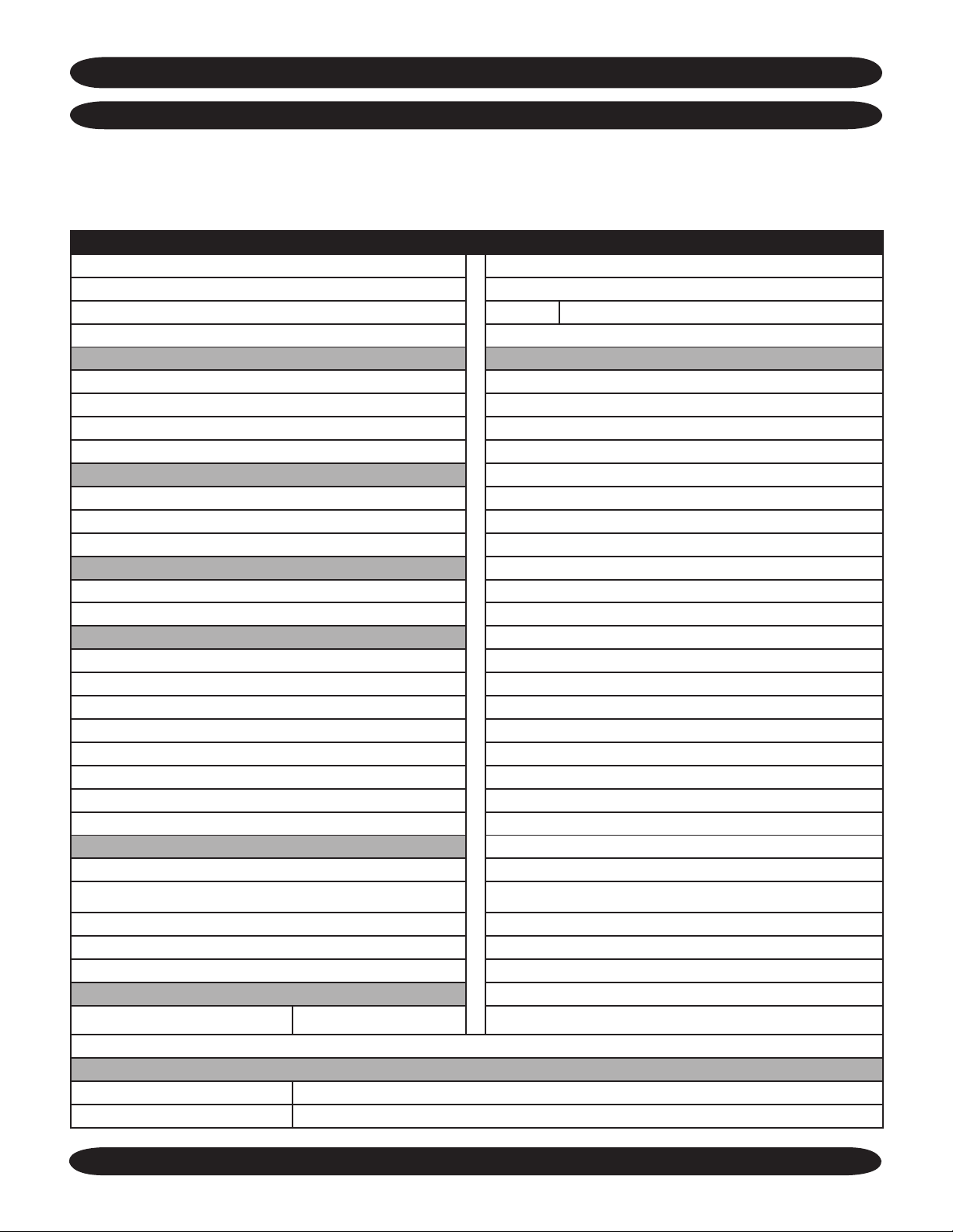
COMMON TO ALL AIR HANDLERS Continued
START-UP, MAINTENANCE AND TROUBLESHOOTING PROCEDURE
The Test Unit Performance Data sheet below is provided
for use by a qualified service professional. In order for our
Technical Service Department to better serve you, please
Make sure to include the Model Number, Serial Number,
Date of Installation.
Call our Technical Support Department
complete and have this information ready when calling.
Test Unit Performance Data
Date:
Model Number Technician:
Serial Number Mode: Cooling
Indoor Section Notes
Evaporator Entering Air - DB
Evaporator Entering Air - WB
Evaporator Leaving Air - DB
Evaporator Leaving Air - WB
Outdoor Section
Entering Air
Leaving Air
Temperature Split
Operating Pressures
Compressor Suction - PSIG
Compressor Discharge - PSIG
Power Input
Compressor - Volts
Compressor - Amps
OD Fan Motor - Volts
OD Fan Motor - Amps
ID Fan Motor - Volts
ID Fan Motor - Amps
Total Volts
Total Amps
Temperatures - Degrees F°
Compressor Suction
Compressor Discharge
@ 1-800-228-9364.
Liquid Out Cond.
Liquid before Expansion
Suction out Evaporator
Capacity Calculations
DB - Temp Split at evap.
Compressor Superheat
Sub Cooling
The Ductless Split System of Choice
Test Summary
23
www.enviromaster.com
Page 24
COMMON TO ALL AIR HANDLERS
MAINTENANCE AND TROUBLESHOOTING PROCEDURE
for EMI Air Handlers with Unit Mount Infrared Controls
MAINTENANCE
Service should be performed by a qualified service
agency and an annual system check is recommended. EMI
units are designed and constructed for reliability and long life
with minimal maintenance. You can insure peak operating
efficiency by:
1. Cleaning air filters on a monthly basis: The filter is accessed by removing the air intake access panel.
TROUBLESHOOTING
EMI AIR HANDLERS WITH
UNIT MOUNT INFRARED CONTROLS
WARNING
!
All service should be performed by a qualified service
technician. Before removing access panels or control
covers to expose moving parts of non-insulated live
electrical components for service, disconnect all high
Volt power supplies to both the indoor unit and outdoor
unit. Failure to do so could result in physical injury and/or
electrical shock.
When trouble-shooting the indoor unit, please refer to the
wiring diagram that is supplied with the equipment. It is
located either on the on the back of the removable return
air grill (WHP/WCP) or on the back of the access panel
(CHP/CCP and FHP/FCP). If you are unable to locate the
wiring diagram please feel free to call the factory technical
service line at (800) 228-9364 and one can be faxed or
mailed. Please have the full model and serial number
available prior to calling.
!
2. Clean with a vacuum cleaner that has a brush attachment or use a garden hose. Allowing dust to collect
on the filter will cause the unit to lose efficiency and
eventually malfunction.
3. Vacuuming dust from the return air grille and coil
surface when cleaning the filter.
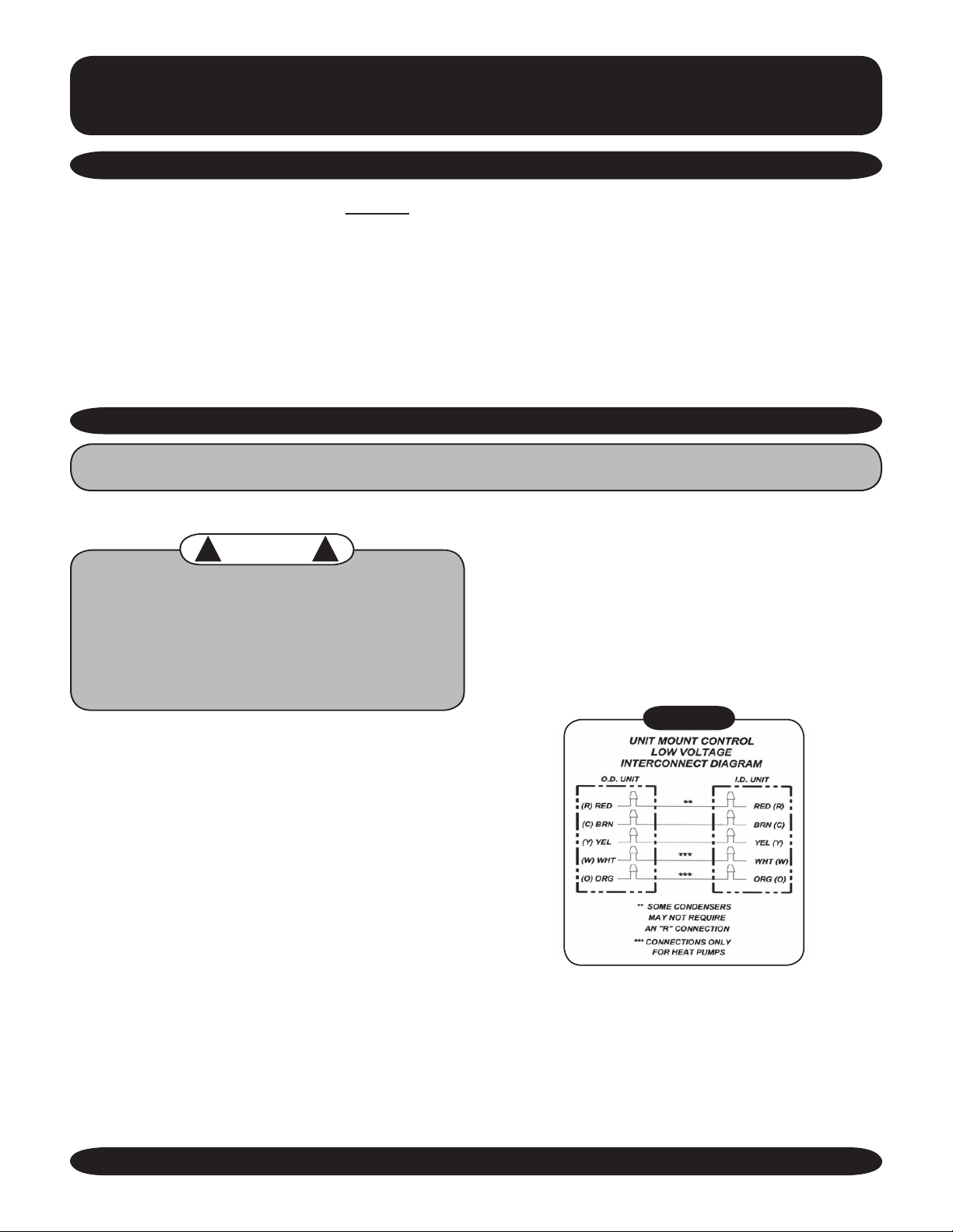
transformer located in the indoor air-handler provides the
Volt power source for the controls. The number of low
low
Volt interconnect conductors will be three to six depending
on heating options and or thermostat selection. Interconnect
wire should be at least 18 awg. Refer to the unit wiring
diagram for the interconnect diagram that matches your
system.
Figure 1
EMI America Series evaporators are designed to operate
with EMI America Series
(indoor unit) and condenser (outdoor unit) are to be
independently connected to the electrical service panel and
protected by separate time delay fuse or HACR breakers.
(See the unit name plate for the correct breaker type and
size). The indoor and outdoor units are also connected to
each other via a 24V interconnect wiring. As of 12/01/04, a
Made in Rome, New York, USA
condensers. The evaporator
24
E-mail: [email protected]
Page 25
TROUBLESHOOTING PROCEDURE Continued
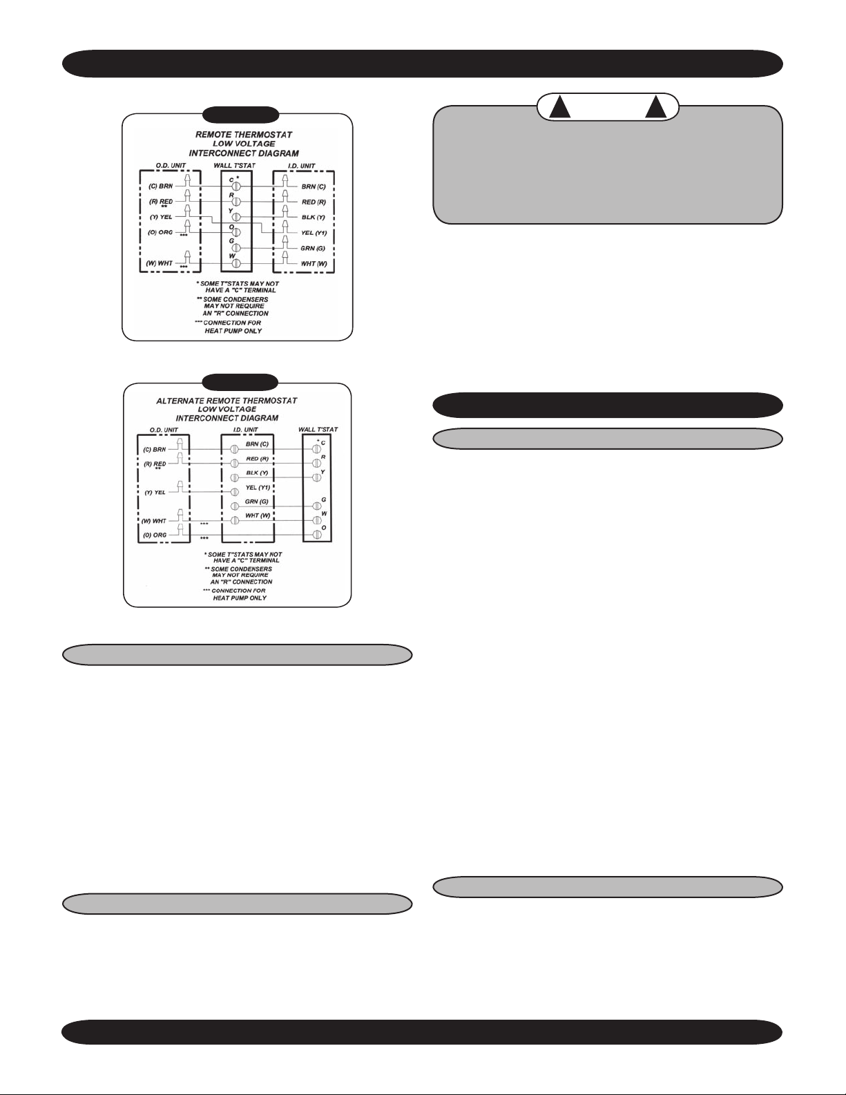
Figure 2
Figure 2 A
POWER SUPPLY CHECK
When trouble shooting any EMI product, it is important
to first check the rating plate for proper field voltage and
breaker size. Secondly using a voltmeter check the incoming
power supply to see that it agrees with the rating plate. The
incoming power should not exceed the nameplate voltage.
Also, the incoming power should not be below the minimum
voltage stated on the rating plate (197V for units rated
208/230V and 104V for units rated 115V).
A check for low voltage power should also be made. By
placing a voltmeter across low
at the indoor unit, there should be a reading of 24V.
TEST MODE
Test mode is available only on units with unit mounted
controls. Use of the test mode feature can aid in the
functional check of the unit. It can also be a helpful tool
when trouble shooting to help isolate a problem source.
Volt terminals “R” and “C”
CAUTION
!
While in test mode, all timers are eliminated. Avoid
short cycling the compressor. After system checks
are complete, the control must be returned to normal
operation. DO NOT LEAVE THE SYSTEM IN TEST
MODE!
To enter test mode the unit must first be in the off state.
Next, using the unit mounted keypad depress both the
up and down arrow buttons simultaneously and push the
On/Off button in for one second. The unit is now in test
mode. System function checks can now be made without
having to wait for timer delays. To return to normal operation,
switch the unit off again via the On/Off button for at least
30 seconds. When the system is switched back on, normal
operation will resume.
LOW VOLT CONTROLS
COOLING ONLY UNITS
Cooling only units utilize low Volt interconnecting
wires between the indoor unit, outd oor units and
thermostat. For air handlers with unit mounted controls,
wires (WCP/WHP) or terminals (CCP/CHP/FCP/FHP)
designated “Y” (yellow) and “C” (brown) of the indoor air
handler should be connected to the corresponding “Y”
(yellow) and “C” (brown) wires or terminals of the outdoor
condenser. Other wires or terminals such as “R”(red) or
“O” (orange) may not be needed and should be protect
by a wire nut from making contact with the junction box or
other metal surfaces.
Refer to low volt interconnect diagram interconnect diagram
Figure 1 for unit mounted controls and Figure 2 for remote
thermostat connection.
A 24V transformer located in the indoor air handler unit
(as of 12/01/04) provides low Volt control power to both the
indoor air handler and outdoor condenser. The 24V power
supply can be measured by placing a meter across the “R”
and “C” low Volt terminals of the air handler. The air handler
will switch on and off the condenser through the yellow (Y)
wire. When the air handler is calling for cooling, 24V can be
measured between terminals (wires) Y and C.
ELECTRIC HEAT
Units with electric heat utilize a control relay located on the
circuit board in the control box. As a safety feature, an auto
resetting limit switch located on the heater end plate or on
the heater assembly will interrupt power to the heater should
an over-heat condition occur. Each electric heat assembly
!
The Ductless Split System of Choice
25
www.enviromaster.com
Page 26

TROUBLESHOOTING PROCEDURE Continued
is also equipped with a one time fuse link. Should electric
heat temperatures rise above the auto resetting limit switch,
a non-resetting, one time fuse link will open and the heater
will remain off.
The following current values apply when the unit is connected
to a 230V power supply. These values include fan motor
current. If the supply power is different, this will in turn affect
the amp draw of the heater.
5kw = 22.3 amps, 4kw = 18 amps, 3kw = 13.5 amps.
Optional Heat pump with Electric Heat
Heat pump units with electric heat utilize four to six
interconnecting, low Volt wires depending control setup
and/or thermostat selected. Refer to the low Volt interconnect
section and figures 1, 2 and 3 for your particular unit. As
of 12/01/04, a 24V transformer located in the indoor
air handler provides low Volt control power to both the air
handler and condenser. With high Volt power supplied to the
condenser, 24V can be measured across the red (R) and
brown (C) wires at all times.
Cooling:
The air handler will cycle the condenser on and off through
the yellow (Y) wire. To check for a condenser signal, select
cooling mode on the indoor unit or thermostat and place
the set-point temperature below room temperature. Then,
with a voltmeter check for 24 Volts across the yellow (Y)
and brown (C) wires. If no signal is found then re-check
all wiring connections to ensure that they match the low
volt interconnect diagram. Check the output of the 24V
transformer (located in the air handler as of 12/01/04) to
ensure that the control voltage is present.
EMI heat pump systems utilize a reversing valve is that is
energized in the cooling mode. The reversing-valve signal
is provided through the orange (O) low
handler or thermostat. It should remain energized constantly
as long as the indoor unit or thermostat remains in cooling
mode. To check for 24V reversing valve voltage, at the
outdoor unit, place a voltmeter across the brown (C) and
orange (O) wires while in the cooling mode.
Heating:
Heat pump units can accommodate two-stage heating when
an optional electric strip heater is present along with a heat
pump condenser. The first stage being the compressor and
the second is electric heat. The air handler or wall thermostat
will cycle the condenser through the yellow (Y) wire as it does
in cooling however the reversing valve will not be energized.
To check for a condenser signal, place the indoor unit or wall
thermostat in heating. Next
one degree above room temperature to call the first stage
place the set-point temperature
Volt wire of the air
of heating. Then, with a voltmeter check for 24 Volts across
the yellow (Y) and brown (C) wires at the condenser. The
electric heat should be off at this point. Select a set-point
temperature that is more than two degrees above the
room temperature to call for the second stage of heating.
The electric heat should energize along with the 24V
compressor signal between “Y” and “C”. Check to see that
the amp draw corresponds with the electric heat rating.
The following current values apply when the unit is
connected to a 230V power supply. These values include
indoor fan motor current. If the supply power is different,
this will affect the amp draw of the heater.
5kw = 22.3 amps, 4kw = 18 amps, 3kw = 13.5 amps.
Units with electric heat utilize a control relay located on the
circuit board in the control box. As a safety feature, an auto
resetting limit switch located on the heater end plate or on
the heater assembly will interrupt power to the heater should
an over-heat condition occur. Each electric heat assembly
is also equipped with a one time fuse link. Should electric
heat temperatures rise above the auto resetting limit switch,
a non-resetting, one time fuse link will open and the heater
will remain off.
Units With Condensation Pumps
EMI Air Handlers are available with an optional condensate
pump. Condensate pumps are recommended when it is not
possible to gravity drain the condensation from the indoor
unit. Depending on the pump manufacture the maximum
lift for the pump will vary. Consult the pump instructions for
the maximum lift for the particular pump being used.
Condensation generated by the evaporator will collect in the
pumps’ reservoir. When the water level is high enough, a
float switch will close and energize the pump motor clearing
the water from the reservoir. Should for any reason the
water exceed the maximum preset level, a safety switch will
open, there by interrupting the (Y) signal to the condenser.
This will prevent the evaporator from generating more
condensation and spilling out of the unit.
Error Codes
Should for some reason one of the two temperature
sensors become disconnected or fail, an error code
will appear in the display. The control will not operate
properly until the sensor is working.
E1 – Coil Sensor malfunction or disconnected. Check
location J1 on thermostat board.
E2 – Room Air Sensor malfunction or disconnected. Check
location J2 on thermostat board.
Made in Rome, New York, USA
26
E-mail: [email protected]
Page 27

TROUBLESHOOTING PROCEDURE Continued
Frequently Asked Questions
Q: The system has just been installed using an EMI indoor
unit and a non-EMI condenser. There is no display and
the unit will not operate.
A: As of 12/01/04 EMI air handlers will be manufactured
with a low
time, EMI outdoor condensers will be manufactures
without a low Volt transformer. When connecting
an EMI evaporator to a non-EMI condenser, check to
ensure that there is a 24V control transformer in either
in the indoor unit or outdoor unit. Only one transformer is
required. If a transformer is not present then one should
be added to the indoor unit. If both the indoor unit and
outdoor unit contain a transformer, one must be removed
from the system.
Q: The condenser will not start although the indoor unit
appears normal. What should I do?
A: At the indoor unit, make sure that the control is in cooling
and the setpoint temperature is below room temperature.
Next, using a volt meter, check for 24
(Y) and brown (C) wires. If 24V is present then check
for wiring breaks or improper connections between the
indoor and outdoor units.
A: Some EMI condensers are equipped with a manual reset
high-pressure switch. It is located on the high side of the
system usually on the discharge line of the compressor.
To reset, simply push the red button in. If the switch was
tripped there will be a “click” when it resets.
A: If the unit is equipped with a condensate pump check to
see if the safety float has been tripped. This can be done
by first disconnecting both ends of the float switch. Then
with an Ohmmeter, check for continuity across the switch.
If the switch is open then the pump is not clearing or the
switch may be bad.
Q: The display on the indoor unit is blank. What should I do?
A: Check the power supply (see “Power supply check”
Section). If the unit still fails to turn on via the On/off
button then inspect the control box for any apparent wires
that may have come loose during shipping. Also inspect
the circuit boards for burnt components. If no obvious
problem can be found then replace all circuit boards
including the unit keypad. Do not attempt to trouble shoot
the individual circuit boards.
Q: The display tends to flicker at times. Is this normal?
A: A small amount of flickering of the display is normal.
Depending on the room lighting, flickering may be more
noticeable at some times than others.
Volt transformer installed. At the same
V across the yellow
Q: How long will the fan run?
A: While the unit is in cooling or heating and auto fan
mode is selected, Fan speed will be determined by the
microprocessor and speed adjustment will be made
according to room and setpoint temperatures. The
fan will switch to High speed when room temperature
deviates by more than two degrees from setpoint. The
fan will switch to Low speed if the deviation is one
degree. When the room temperature reaches setpoint
temperature the heat/cool call is dropped. The fan will
then stay on for an additional 60 sec. to purge unit of any
residual energy. If High or Low is selected then the fan
will operate continuous regardless of set point or room
temperatures.
Q: What causes my indoor unit to freeze-up?
A: Evaporator freeze up is usually the symptom of another
problem. Units with infrared compatible, unit mounted
controls are equipped with freeze protection to prevent
freeze up from occurring. If freeze up does occur then
check the following.
• Check that the freeze sensor located in the lowest
part of the coil. Generally this is where freeze up
will begin.
• Check that the freeze sensor inserted fully and snug
in the coil fin. If not another location may need to be
selected. Be careful not to insert the sensor directly
into the coil tube rather insert the sensor between two
tubes.
• Check the indoor air filter. It should be clean and free
of dirt. A dirty filter will reduce airflow and efficiency.
Also check that the coil is clean. If the coil is dirty then
it should be cleaned using an appropriate coil cleaner
or mild detergent.
• Is the equipment being operated in cooling mode
when outdoor temperatures are below 65°F? If it is,
then the condenser should be fitted with low ambient
control so that the proper system pressures are
maintained.
• Does the system have the proper refrigerant charge?
A system low on refrigerant can cause evaporator
freeze-up. To check system charge you will need to
contact a qualified refrigeration service technician.
Refrigerant charge information can be found in IOM
for the outdoor condensing unit.
The Ductless Split System of Choice
27
www.enviromaster.com
Page 28
ALL PRODUCT LIMITED WARRANTY
Enviromaster International LLC (EMI) warrants to the purchaser/owner that EMI products will be free from defects in material and workmanship under the normal use and maintenance for a period of twelve months for all
components and sixty months on unit compressors from the date of original installation, or fifteen months for
all components and sixty-three months on unit compressors from the date of manufacture, whichever comes
first.
WHAT WE WILL COVER
EMI will replace any defective part returned to EMI’s approved service organization with a new or rebuilt part at
no charge. The replacement part assumes that unused portion of this warranty.
WHAT WE DON’T COVER
THIS WARRANTY DOES NOT INCLUDE LABOR or other costs incurred for repairing, removing, installing,
shipping, servicing, or handling of either defective or replacement parts.
EMI IS NOT RESPONSIBLE FOR:
• Normal maintenance
• Damage or repairs required as a consequence of faulty installation or application by others.
• Failure to start due to voltage conditions, blown fuses, open circuit breakers, or other damages due to the
inadequacy or interruption of electrical service.
• Damage or repairs needed as a consequence of any misapplication, abuse, improper servicing, unauthorized
alteration, or improper operation.
• Damage as a result of floods, winds, fires, lightening, accidents, corrosive atmosphere, or other conditions
beyond the control of EMI.
• Parts not supplied or designated by EMI.
• Products installed outside the United States or Canada.
• Any damages to person or property of whatever kind, direct or indirect, special or consequential, whether
resulting from use or loss of use of the product.
LIMITATION OF WARRANTIES
This warranty is exclusive and in lieu of any implied warranties of merchantability and fitness for a particular
purpose and all other warranties express or implied. The remedies provided for in this warranty are exclusive
and shall constitute the only liabilities on the part of EMI including any statements made by any individual which
shall be of no effect.
FOR SERVICE OR REPAIR:
(1) Contact the Installer
(2) Call the nearest Distributor
(3) Call or write:
Made in Rome, New York, USA
28
ENVIROMASTER INTERNATIONAL LLC
5780 Success Drive, Rome, NY 13440
E-mail: [email protected]
 Loading...