

Envirolite EVTF1045R3-35 Installation Instructions Manual
EVTF1045R3-35
FOUR LIGHT LED FIXED TRACK
Questions, problems, missing parts? Before returning to the store,
call Envirolite Customer Service
8 a.m. – 6 p.m., EST, Monday – Friday
1-855-573-6156
WARRANTY
WHAT IS COVERED
The manufacturer warrants this lighting fixture to be free from defects in materials and
workmanship for a period of five (5) years from date of purchase. This warranty applies
only to the original consumer purchaser and only to products used in normal use and
service. If this product is found to be defective, the manufacturer’s only obligation, and
your exclusive remedy, is the repair or replacement of the product at the manufacturer’s
discretion, provided that the product has not been damaged through misuse, abuse,
accident, modifications, alterations, neglect or mishandling.
WHAT IS NOT COVERED
This warranty shall not apply to any product that is found to have been improperly
installed, set-up, or used in any way not in accordance with the instructions supplied with
the product. This warranty shall not apply to a failure of the product as a result of an
accident, misuse, abuse, negligence, alteration, or faulty installation, or any other failure
not relating to faulty material or workmanship. This warranty shall not apply to the finish
on any portion of the product, such as surface and/or weathering, as this is considered
normal wear and tear.
The manufacturer does not warrant and specially disclaims any warranty, whether
expressed or implied, of fitness for a particular purpose, other than the warranty
contained herein. The manufacturer specifically disclaims any liability and shall not be
liable for any consequential or incidental loss or damage, including but not limited to any
labor/expense costs involved in the replacement or repair of said product.
SAFETY INFORMATION
WARNING: Disconnect the power prior to removing or installing a light fixture.
Before installing this fixture or removing a previous fixture, disconnect the power by
turning off the circuit breaker or by removing the fuse at the fuse box.
Consult a qualified electrician if you have any electrical questions or need to replace
the driver.
If you have any non-electrical questions about this fixture, please contact our
Customer Service Team at 1-855-573-6156.
PLANNING THE INSTALLATION
WARNING: This fixture has a built-in dimmer. Do not connect an external dimmer on
this light fixture. Doing so will prevent the fixture from functioning properly.
NOTE: Keep your receipt and these instructions for proof of purchase.
Read all instructions before assembling and installation your fixture. Before installing the
fixture or removing a previous fixture, disconnect the power by turning off the circuit
breaker or by removing the fuse at the fuse box. To avoid damaging this product,
assemble it on a soft, non-abrasive surface such as carpet or cardboard.
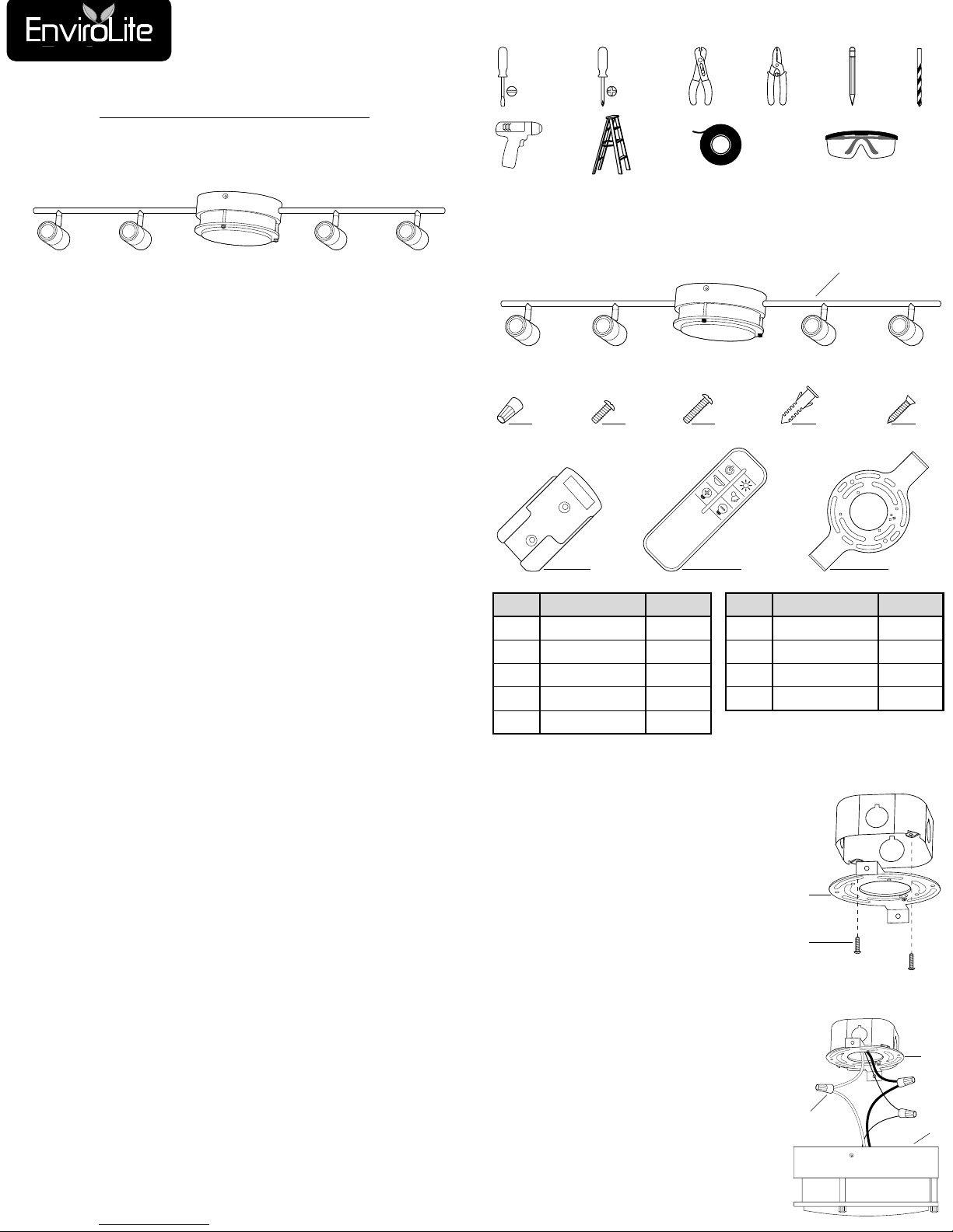
PACKAGE CONTENTS
NOTE: Contents are not shown to size.
Part
Description
Quantity
AA
Fixture
1
BB
Wire Nut
3
CC
Canopy Screw
2
DD
Mounting
Screw 2
EE
Ceiling Anchor
2
TOOLS REQUIRED
Ladder
Electrical
Tape
Safety
Goggles
Drill
Wire
Cutter
Flat Head
Screwdriver
Phillips
Screwdriver
Wire
Stripper
Pencil
Drill
Bit
Part
Description
Quantity
FF
Anchor Screw
2
GG
Remote
Mount 1
HH
Remote Control
1
II
Mounting Bracket
1
AA
II HH GG
BB CC DD EE FF
STEP 1
Mount the mounting bracket (II) to the
outlet box using the mounting screws
(DD).
STEP 2
NOTE: If you have electrical questions
consult your local electrical code
for approved grounding methods.
Connect the black supply wire to the
black fixture wire using a wire nut (BB).
Connect the white supply wire to the
white fixture wire using a wire nut (BB).
Connect the fixture ground wire and the
supply ground wire together using a wire
nut (BB).
Wrap all wire connections with electrical
tape for a more secure connection.
Carefully tuck all wires and wire nuts
(BB) into the outlet box.
II
DD
II
AA
BB
INSTALLATION INSTRUCTIONS
INSTALLATION INSTRUCTIONS (continued)
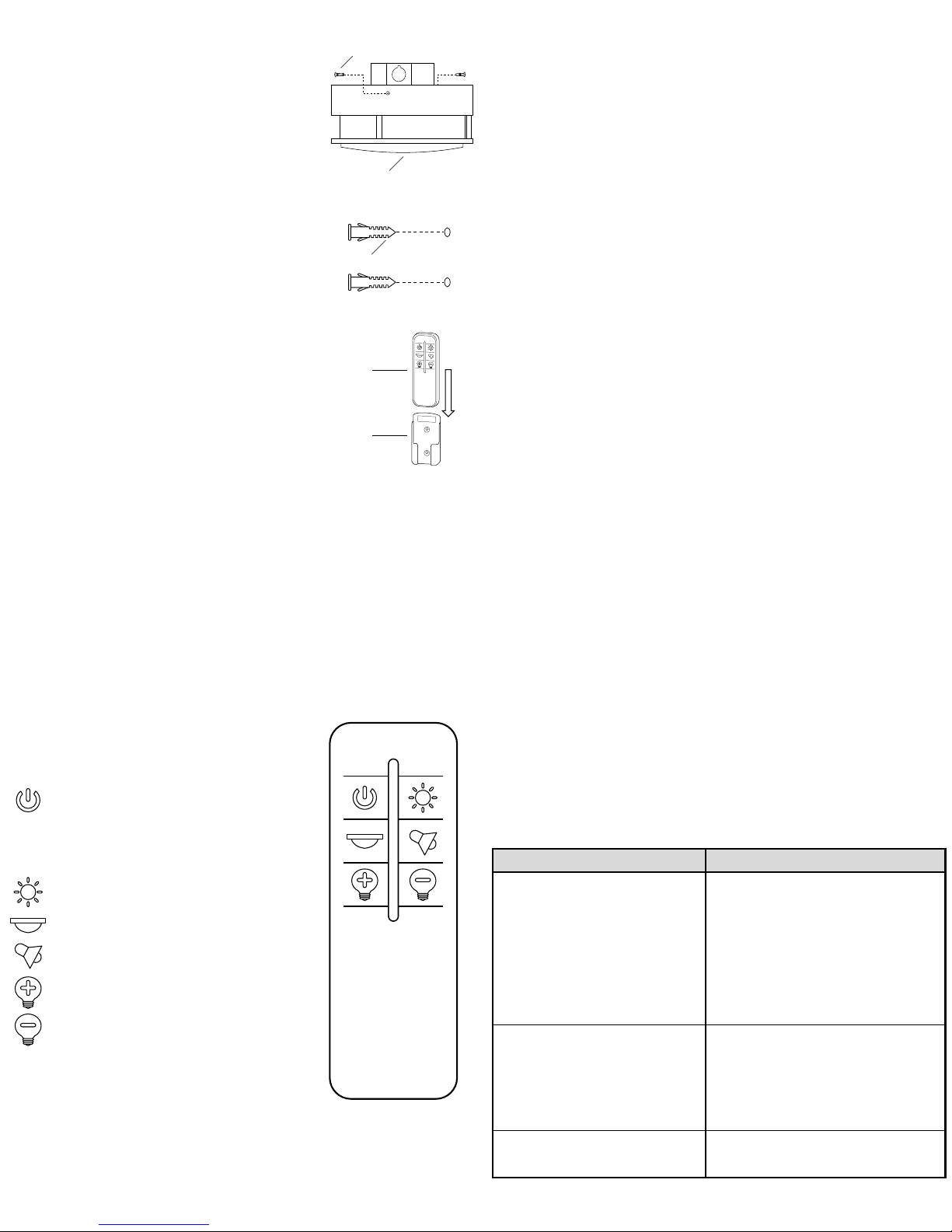
STEP 3
Place the canopy of the fixture (AA) over the outlet
box and flush against the ceiling surface.
Align the holes on the mounting bracket (II) to the
holes on the fixture (AA).
Secure the canopy of the fixture (AA) using the
canopy screws (CC).
STEP 4
Place the remote mount (GG) on the desired
location of your wall and mark the mounting holes
with a pencil.
Use a 0.25 in drill bit to drill the two holes into your
wall.
Tap in an wall anchor (EE) into each hole.
STEP 5
Align the remote mount (GG) over the holes and
secure the remote mount (GG) in place using the
anchor screws (FF).
OPERATION
NOTE: The fixture has with an internal dimmer. Do not connect the fixture to an
external dimmer. Doing so may prevent the fixture from operating as intended.
NOTE: The light switch must be on in order to control the light fixture with the remote
control.
Turn on the power at the circuit breaker or fuse box.
Turn the light switch on to activate the fixture.
REMOTE CONTROL
BUTTON FUNCTIONS
Power ON/OFF.
OFF: Turns off all the lights. Other remote buttons
cannot be used in the off state.
ON: Turns the lights on and returns it to the last
settings used.
Turn the flush mount and track heads on
at the same time at 100% brightness.
Turn only the flush mount on (100% brightness).
Turn only the track heads on (100% brightness).
Dim the light up (brighten).
Dim the light down.
PAIRING FIXTURES
NOTE: The remote control can pair 1 to 4 lights at the simultaneously.
You must be within an unobstructed distance of 2 – 3 meters (6-10 feet) to pair
your remote to your light fixture.
Long press the ON/OFF key for 5 seconds. The red indicator on the remote will
flash three times, indicating that the fixture has been paired.
Problem
Solution
The
light will not turn on. 1. Make sure the power supply is on.
2. Test or replace the switch.
3. Check the wiring.
4. Check that the batteries on the remote
control are working.
5. Ensure the fixture is paired to the
remote control.
6. Ensure you are within an unobstructed
operating distance.
The product receiving information is out
of sync.
7. Check solutions 1-6 and confirm that
everything is correct.
8. Try to disconnect the battery to repower.
9. Disconnect the wall switch and power
on again.
The
fuse blows or circuit breaker trips
when light is turned on.
10. Check the wire connections.
AA
CC
EE
GG
HH
REMOTE CONTROL (continued)
DISCONNECTING FIXTURES
Long press the ON/OFF key for 5 seconds. The red indicator on the remote will
flash five times, indicating that the fixture is no longer paired to the remote.
OPERATING DISTANCE
An unobstructed remote can function up to a distance of 6 – 9 meters (20 – 30
feet).
FCC NOTICE
This device complies with Part 15 of the FCC rules. Operation is subject to the following t
wo conditions: (1) This device may not cause harmful interference; and (2) this device m
ust accept any interference received, including interference that may cause undesired op
eration.
NOTE 1: This device has been tested and found to comply with the limits for a Class B
digital device, pursuant to part 15 of the FCC Rules. These limits are designed to provide
reasonable protection against harmful interference in a residential installation. This
equipment generates, uses and can radiate radio frequency energy and, if not installed
and used in accordance with the instruction manual, may cause harmful interference to
radio communications. However, there is no guarantee that interference can be
determined by turning the equipment off and on, the user is encouraged to try to correct
the interface by one or more of the following measures:
Reorient or relocate the receiving antenna.
Increase the separation between the device and receiver.
Connect the equipment into an outlet on a circuit different from that to which the
receiver is connected.
Consult the dealer or an experienced radio/TV technician for help.
NOTE 2: Any changes or modifications not expressly approved by the party responsible
for compliance could void the user’s authority to operate the equipment.
IC NOTICE
This device complies with Industry Canada’s license-exempt RSSs. Operation is subject
to the following two conditions:
(1) This device may not cause interference; and (2) this device must accept any
interference, including interference that may cause undesired operation of the device.
TROUBLESHOOTING
 Loading...