

Page 1
IOM
Installation
Operation &
Maintenance
E Series
Seal-less Internal
Gear Pumps
Where Innovation Flows
envirogearpump.com
Page 2

SECTION X
TABLE OF CONTENTS
SECTION 1 CAUTIONS—READ FIRST! ...................................................1
SECTION 2 PUMP DESIGNATION SYSTEM ..............................................3
SECTION 3 HOW IT WORKS – INTERNAL GEAR TECHNOLOGY .........................4
SECTION 4 TECHNICAL INFORMATION
Sizes Available ..................................................................5
Pump Selection Performance Criteria .............................................5
Temperature Ratings ............................................................6
Magnetic-Coupling Strengths ....................................................7
Relief Valve Performance .........................................................8
Internal Cooling Circuit ..........................................................9
Rotation and Port Orientation ...................................................10
SECTION 5 SUGGESTED INSTALLATION & OPERATION ................................11
SECTION 6 PUMP ADJUSTMENTS AND MAINTENANCE ..............................17
SECTION 7 PUMP DISASSEMBLY & REPAIR PROCESSES .............................19
SECTION 8 EXPLODED VIEW & PARTS LISTING ........................................35
SECTION 9 TROUBLESHOOTING .........................................................58
SECTION
10
WARRANTY ..................................................................61
Page 3
WARNING: In any positive-displacement pump system,
a reliable pressure-protection device must be used in the
discharge piping to avoid a dangerous pressure increase, which
could cause the pump or any component in the discharge piping
to burst and can lead to serious injur y. A pump-mounted integral
relief valve is not intended to be used in this manner.
WARNING: This pump contains powerful permanent magnets
that can cause serious injury. Read the appropriate section of
this IOM before doing any service work.
WARNING: Magnetic field can disrupt medical implants such
as pacemakers. Implant wearers should remain a minimum of 0.3
m (1 ft) away from pump and 1 m (3 ft) away from disassembled
magnets.
WARNING: Magnets inside the pump can damage electronic
equipment or magnetic media.
WARNING: This pum p is designed to r otat e only in the di rection
indicated. Do not run the pump in the opposite direction for long
periods because internal passageways that control axial thrust
will not work correctly, causing premature wear and reduced
pumping efficiency.
WARNING: The inner magnets on the back of the rotor
assembly are strongly at tracted to the outer magnets in the
outer-drive assembly. During the separation process, there
will be a strong force of up to 136 kg (300 lbs) trying to pull
them back together, which can create a powerful pinch point.
WARNING: Failure to have each magnet segment in opposite
polarity with adjacent magnets will cause a significant reduction
of coupling torque.
WARNING: Maximum temperature limits are based upon
mechanical stress only. Certain chemicals will significantly
reduce maximum safe operating temperatures. Consult
Chemical Resistance Guide for chemical compatibility and
temperature limits.
WARNING: Prevent static sparking. If static sparking occurs,
fire or explosion could result. Pump, valves and containers
must be grounded to a proper grounding point when handling
flammable fluids and whenever discharge of static electricity is
a hazard.
WARNING: For applications requiring CE or AT E X, refer to the
E Series Safety Supplement for addition cautions and warnings.
CAUTION: Only personnel who are familiar with the operation
and repair of mechanical products should perform the necessary
maintenance. You must familiarize yourself with the entire
contents of this manual prior to operating and/or performing any
maintenance.
CAUTION: When selecting a E Series pump for an application,
you must first ensure that the pump components are compatible
with the process media.
CAUTION: Do not operate this pump in excess of its rated
capacity, pressure, speed and temperature.
CAUTION: Before any maintenance and repair is attempted,
disconnect the drive.
CAUTION: Before any maintenance or repair is attempted, bleed
all pressure from the pump through the suction or discharge lines.
CAUTION: Do not remove any pressure-containing components
during pump operation.
CAUTION: All E Series pumps contain residual hydraulic oil
from the factory production test. Hypar-FG 15 food-grade oil is
the standard production test fluid, but any certified performance
testing may be done on a non-food grade oil, such as Unilube 32
(ISO 32) or Unilube 100 (ISO 100). Determine if this is compatible
with the fluid you are pumping. If the fluid is incompatible, then
the pump must be fully flushed prior to use.
CAUTION: When pumping fluids at elevated temperatures,
care should be taken to gradually increase temperature. Rapid
temperature increase can damage internal components.
CAUTION: Ensure that the pump has cooled to a safe
temperature before any maintenance or repair is attemped.
CAUTION: When pumping fluids at elevated temperatures
the piping may expand, resulting in excessive stress on the
pump. This can cause pump failure. Care must be taken when
considering pipe design to avoid damage from thermal expansion.
CAUTION: All inlet and discharge plumbing should be clean and
free from foreign material prior to startup of pump.
CAUTION: When connecting to an electric motor, follow all
safety recommendations provided by the motor manufacturer.
CAUTION: Never remove safety guards from shafts, couplings,
V-belts or pulleys during operation. Doing so could result in injury.
CAUTION: Do not wear loose or dangling clothing or jewelry
near the equipment. These items could become caught in the
equipment and cause injury.
CAUTION: Before any maintenance or repair is attemped,
ensure that the pump has been thoroughly flushed of any
hazardous fluids. Review the Material Safety Data Sheet (MSDS)
applicable to the fluid for proper handling.
• Crane, hoist or other suitable lif ting device capable of
lifting at least 182 kg (40 0 lbs)
• Sturdy workbench that is positioned beneath the
lifting device and is firmly anchored to the floor, or if
unanchored, the workbench must weigh at least 182 kg
(400 lbs) , and be strong enough to resist a lif ting force of
up to 182 kg (400 lbs)
• Pump Disassembly Tool F-00096 or F-00097
To safely separate the rotor assembly from the outerdrive assembly, follow the instructions below and use the
following equipment:
SECTION 1
CAUTIONS–READ FIRST!
ENV-11000-E-04 1 ENVIROGEAR
Page 4

SECTION X
Always read the most current version of this manual before performing any work on or around this pump. The
most current version of the manual is freely available on the web at www.envirogearpump.com.
EnviroGear pumps are specifically configured for your unique application conditions. Those application
conditions and the details of the pump configuration were documented during the ordering process. Keep
that information available in a safe place, as it may be needed when troubleshooting pump problems or when
ordering spare parts or repairs.
EnviroGear pumps are covered by one or more of the following patents: U.S. Patent Nos. 7549205, 7137793,
7183683; 8,608,465B2 Australian Patent No. AU2005233534B2; Korean Patent No. 10-2006-7023162; Mexican
Patent No. PA/a/2006/011436; Russian Patent No. 2006138540/06(041952); China Patent No. ZL 201280031563.6;
and other patents pending.
ENVIROGEAR 2 ENV-11000-E-04
Page 5
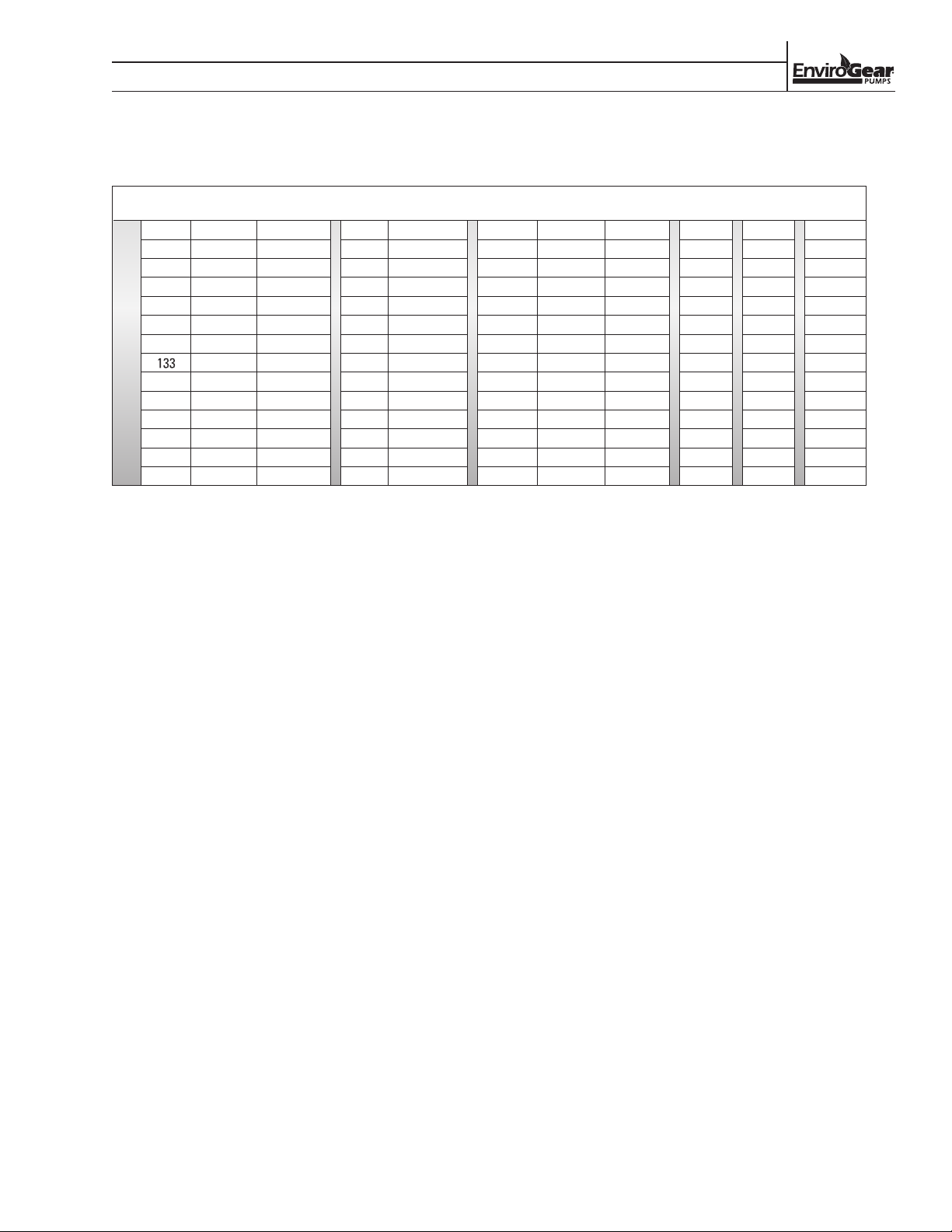
PUMP DESIGNATION SYSTEM
EXAMPLE:
E1-69SA/3ART/TC6L/10/S/310
SECTION 2
MODEL MATERIAL CLEARANCE/PORTS ORIENTATION/O-RINGS BUSHINGS MAGNETS
E1-
2 C A 1.5A RT V B 6L N S XXX
4 D B 1.5B LT T C 6M 05 V
24 S C 1.5D TR S H 6H 07 14
32 W D 1.5N TL K6 R 7L 08 18
55 E 2A RL K7 T 7M 10 21
69 F 2S LR I 7H 12 25
82 2B LB 13
133 2D BR 15
222 2N BL 17
3S RB 20
3S
3D
4A
6S
MODELS:
E1-2 = 2 in3/rev
E1-4 = 4 in3/rev
E1-24 = 24 in3/rev
E1-32 = 32 in3/rev
E1-55 = 55 in3/rev
E1-69 = 69 in3/rev
E1-82 = 82 in3/rev
E1-133 = 133 in3/rev
E1-222 = 222 in3/rev
MATERIALS:
C = CARBON STEEL
D = DUCTILE IRON
S = STAINLESS STEEL
W = CAST IRON
CLEARANCES (E12/4/24/32/55/69/82/133/222):
A = A [<100 cSt, (<149C) <300F]
B = B [100-5000 cSt, (<149C) <300F]
C = C [>5000 cSt, (<149C) <300F]
D = D [<100 cSt, (>149C) >300F]
E = E [100-5000 cSt, (>149C) >300F]
F = F [>5000 cSt,(>149C) >300F ]
PORTS:
1.5A = 1.5" ANSI
1.5B = 1.5" BSPT
1.5D = DN40 (1.5") PN16
1.5N = 1.5" NPT
2A = 2" ANSI
2S = 2" ANSI (180°)
2B = 2" BSPT
2D = DN50 (2") PN16
2N = 2" NPT
3A = 3" ANSI
3S = 3" ANSI (180°)
3D = DN80 (3") PN16
4A = 4" ANSI
6S = 6" ANSI
ORIENTATION:
RT = Right suction, Top discharge
LT = Left suction, Top discharge
TR = Top suction, Right discharge
TL = Top suction, Left discharge
RL = Right suction, Left discharge
LR = Left suction, Right discharge
LB = Left suction, Bottom discharge
BR = Bottom suction, Right discharge
BL = Bottom suction, Left discharge
RB = Right suction, Bottom discharge
O-RINGS:
V = Viton®, DuPont Type "A"
T = FEP-encapsulated Viton
S = PFA-encapsulated silicone
K6 = Kalrez® 6375
K7 = Kalrez® 7075
BUSHINGS:
B = Bronze bushings, Standard Spindle
C = Carbon-graphite bushings, Standard
Spindle
H = Carbon-graphite bushings, Hardened
17-4PH Spindle
R = Resin Impregnated Carbon-graphite
bushings, Standard Spindle
T = Tungsten carbide bushings, Hardened
Spindle
I =
Hardened cast iron bushings, Hardened
Spindle
MAGNETS:
6L = M6L standard-strength / standard-temp.
[(<135C) <275 F]
6M = M6M standard-strength / medium-temp.
[(<190C) <375F]
6H = M6H standard-strength / high-temp.
[(<260C) <500F]
7L = M7L high-strength / standard-temp.
[(<135C) <275 F]
7M = M7M high-strength / medium-temp.
[(<190C) <375F]
7H = M7H high-strength / high-temp.
[(<260C <500F)]
®
RELIEF VALVE (E1-2/4/24/32/55/69/82)
N = NO RELIEF VALVE
05 = Cracks at 50 +/-10 psi delta P
07 = Cracks at 75 +/-10 psi delta P
10 = Cracks at 100 +/-10 psi delta P
12 = Cracks at 125 +/-10 psi delta P
15 = Cracks at 150 +/-10 psi delta P
17 = Cracks at 175 +/-10 psi delta P
20 = Cracks at 200 +/-10 psi delta P
RELIEF VALVE (E1-133/222):
CAST IRON/CARBON STEEL
N = NO RELIEF VALVE
05 = Full bypass at 20 to 50 psi
08 = Full bypass at 51 to 80 psi
13 = Full bypass at 81 to 130 psi
20 = Full bypass at 131 to 200 psi
RELIEF VALVE (E1-133/222):
STAINLESS STEEL
N = NO RELIEF VALVE
05 = Full bypass at 20 to 50 psi
08 = Full bypass at 51 to 80 psi
15 = Full bypass at 81 to 150 psi
SHAFT:
S = Standard shaft (no optional shaft selected)
V = Smaller shaft (matches mtg dims of Viking L/LQ/LL)
14 = Close Coupled 140TC NEMA
18 = Close Coupled 180TC NEMA
21 = Close Coupled 210TC NEMA
25 = Close Coupled 250TC NEMA
SPECIALTY CODE:
Contact Factory
/
RELIEF
VALVE
/
SHAFT
SPECIALTY
/
CODE
ENV-11000-E-04 3 ENVIROGEAR
Page 6
SECTION 3
OUTLET
OUTLET
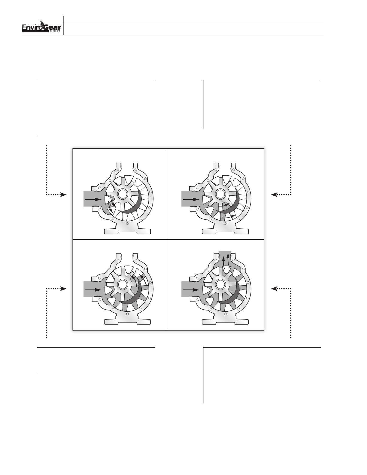
HOW IT WORKS—INTERNAL GEAR TECHNOLOGY
The E SERIES GEAR PUMP is a rotating positive displacement pump. These drawings show the flow pattern through
the pump upon its initial rotation. It is assumed that the pump has no fluid in it prior to its initial rotation.
1
The shaded area indicates the liquid as it
is drawn into the liquid inlet port of the
pump. As the rotor turns, atmospheric
pressure forces the liquid between the
rotor teeth and idler teeth. The two
arrows indicate the rotational direction
of the pump.
OUTLET
INLET
INLET
As the rotor continues to turn, the liquid
2
is forced through the crescent-shaped
area of the wetted path. The crescentshaped area divides the liquid and acts as
a barrier between the inlet and discharge
ports.
OUTLET
INLET
3 4
ENVIROGEAR 4 ENV-11000-E-04
As the rotor continues to turn, the liquid
is forced past the crescent-shaped area
and moves toward the discharge port.
INLET
As the rotor completes one complete
rotation, the rotor and idler teeth
interlock, forcing the liquid through the
discharge of the pump. The pump may
take several rotations to completely
prime depending on the conditions of the
application.
Page 7
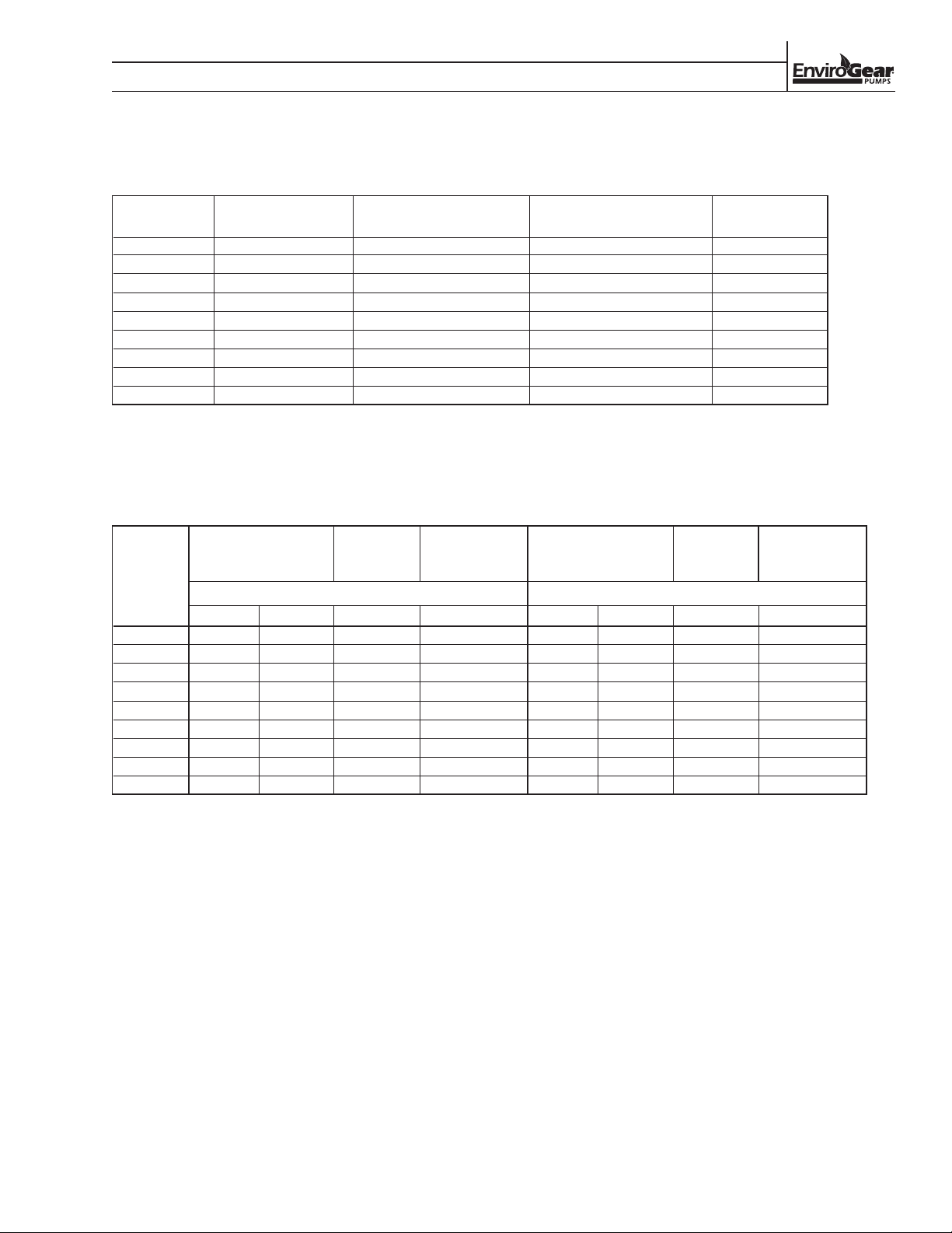
SIZES AVAILABLE
SECTION 4
TECHNICAL INFORMATION
Model
Cast Iron/ Ductile Iron
Port Sizes Carbon Steel Port Sizes
1
Stainless Steel Port Sizes
1
Pump Weight
E1-2 N/A 1-1/2" NPT/ANSI/BSPT 1-1/2" NPT/ANSI/BSPT 24 kg (53 lb)
E1-4 N/A 1-1/2" NPT/ANSI/BSPT 1-1/2" NPT/ANSI/BSPT 24 kg (53 lb)
1
E1-24 2" NPT/ANSI
E1-32 2" NPT/ANSI
E1-55 3" ANSI
E1-69 3" ANSI
E1-82 3" ANSI
E1-133 4" ANSI
E1-222 6" ANSI
1
Flanged connections meet Class 150# ANSI
2
Flanged connections meet Class 125# ANSI
/BSPT 2" NPT/ANSI/BSPT - 3" ANSI 2" NPT/ANSI/BSPT - 3" ANSI 69 kg (152 lb)
1
/BSPT 2" NPT/ANSI/BSPT - 3" ANSI 2" NPT/ANSI/BSPT - 3" ANSI 69 kg (152 lb)
1
- 4" ANSI
1
- 4" ANSI
1
- 4" ANSI
2
2
1
1
1
3" ANSI - 4" ANSI 3" ANSI - 4" ANSI 139 kg (307 lb)
3" ANSI - 4" ANSI 3" ANSI - 4" ANSI 139 kg (307 lb)
3" ANSI - 4" ANSI 3" ANSI - 4" ANSI 139 kg (307 lb)
4" ANSI 4" ANSI 250 kg (552 lb)
6" ANSI 6" ANSI 270 kg (596 lb)
PUMP SELECTION PERFORMANCE CRITERIA
1,2
Max.
Nominal Pump Rating
Discharge
Pressure
Max.
Temperature Nominal Pump Rating
CAST IRON / DUCTILE IRON / CARBON STEEL STAINLESS STEEL
Model
rpm m
3
/h (gpm) bar (psig) Celsius (Fahrenheit) rpm m3/h (gpm) bar (psig) Celsius (Fahrenheit)
E1-2 1,750 3.4 (15) 13.8 (200) 260° (500°) 1,150 2.3 (10) 10.3 (150) 260° (500°)
E1-4 1,750 6.8 (30) 13.8 (200) 260° (500°) 1,150 4.5 (20) 10.3 (150) 260° (500°)
E1-24 780 17.0 (75) 13.8 (200) 260° (500°) 640 12.5 (55) 10.3 (150) 260° (500°)
E1-32 780 22.7 (100) 13.8 (200) 260° (500°) 640 18.2 (80) 10.3 (150) 260° (500°)
E1-55 640 30.7 (135) 13.8 (200) 260° (500°) 520 25.0 (110) 10.3 (150) 260° (500°)
E1-69 640 38.6 (170) 13.8 (200) 260° (500°) 520 31.8 (140) 10.3 (150) 260° (500°)
E1-82 640 45.4 (200) 13.8 (200) 260° (500°) 520 36.3 (160) 10.3 (150) 260° (500°)
E1-133 520 68.1 (300) 13.8 (200) 260° (500°) 520 68.1 (300) 10.3 (150) 260° (500°)
E1-222 520 113.6 (500) 13.8 (200) 260° (500°) 520 113.6 (500) 10.3 (150) 260° (500°)
1
Maximum pressure listed reflects maximum differential pressure and maximum allowable working pressure
2
Consult factory for differential pressures below 1.4 bar (20 psig)
1,2
Max.
Discharge
Pressure
Temperature
Max.
ENV-11000-E-04 5 ENVIROGEAR
Page 8
SECTION 4
TECHNICAL INFORMATION
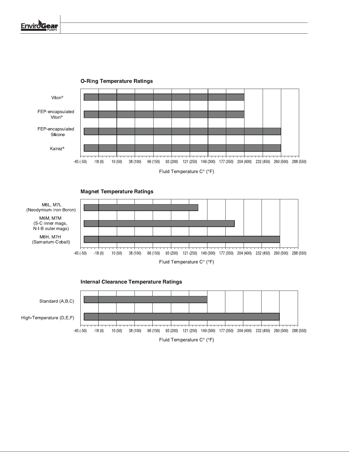
TEM PER ATURE RATI NGS
ENVIROGEAR 6 ENV-11000-E-04
Page 9
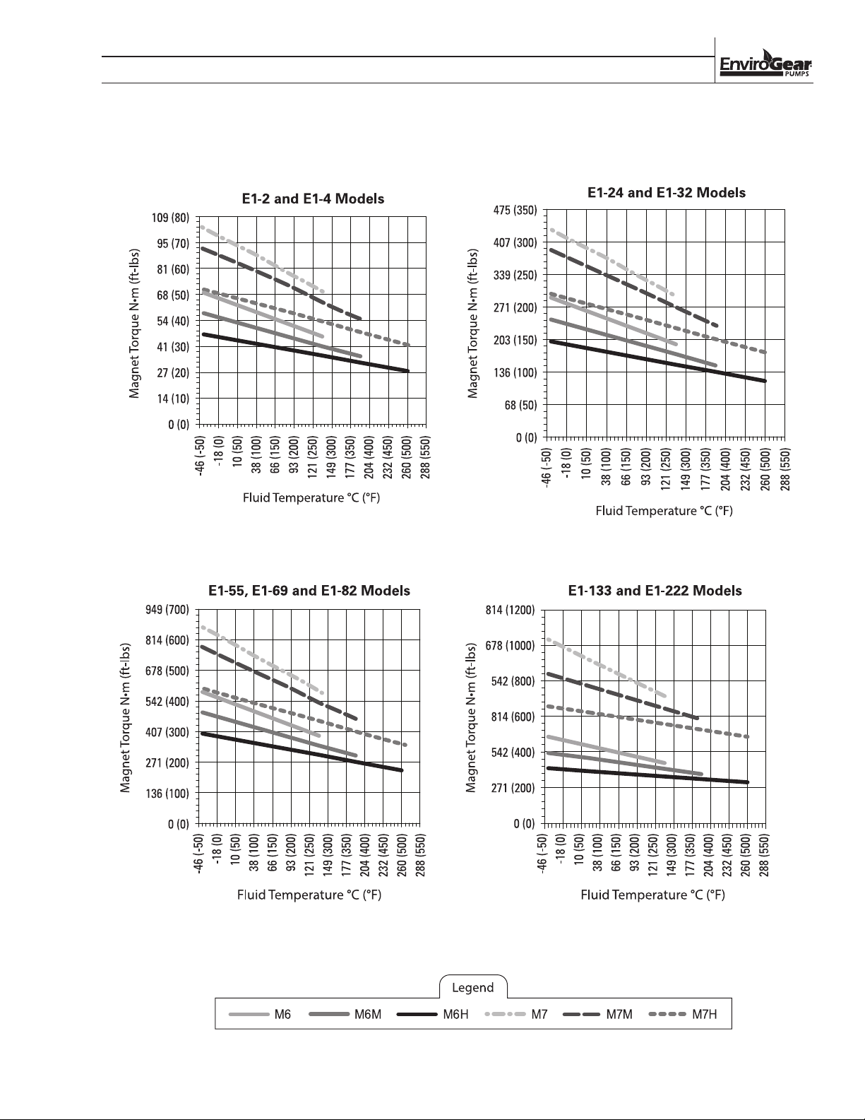
MAGNETIC-COUPLING STRENGTHS
SECTION X
TECHNICAL INFORMATION
ENV-11000-E-04 7 ENVIROGEAR
Page 10
SECTION X
TECHNICAL INFORMATION
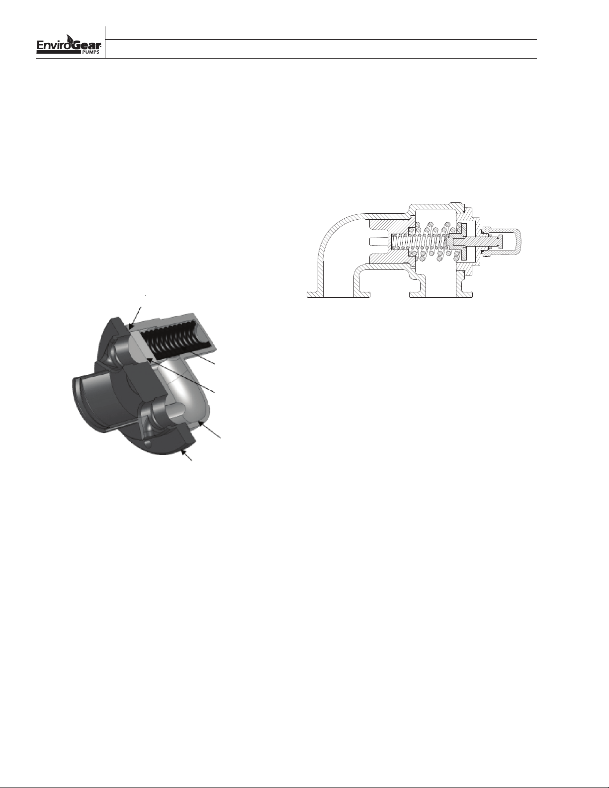
RELIEF VALVE PERFORMANCE
Optional integral relief valves provide pump protection
from over-pressure conditions. While not intended for
continuous use, internal relief valves protect the pump
from closed discharge valves or other intermittent
over-pressurization of the system.
Depending on the size of the pump, you will get one
of two relief valve designs, a non-externally adjustable
or an externally adjustable relief valve. The design
of the E1-2 thru E1-82 are spring-loaded and contain
only three parts. This design addresses the problem of
over-pressurization by “cracking” (where the poppet
lifts off the seat) at the nominal pressure-relief setting,
allowing pumped fluid to recirculate internally from the
discharge side back to the suction side.
O-ring
PRESSURE
SIDE
SUCTION
SIDE
spring
poppet
valve body
head
RELIEF VALVE PERFORMANCE
The design of E1-133 and E1-222 is spring-loaded and
externally adjustable. It addresses the problem of over
pressurization by initially cracking, and eventually
full-bypassing at the nominal pressure-relief setting,
allowing pump fluid to recirculate internally from the
discharge side back to the suction side.
Relief Valve – E1-133 and E1-222 Models
To properly size the integral relief valve, it is important
to understand the difference between crack pressure
and full bypass pressure.
Crack pressure is the pressure at which the poppet just
begins to lift off the seat. This pressure is not affected
by variations in fluid viscosity or pump speed. The
pump will provide full flow rate at all pressures below
the cracking pressure. E1-2 through E-82 pressure relief
valves are sized based on cracking pressure.
Relief Valve – E1-2 thru E1-82 Models
Full bypass pressure is the pressure that occurs when
100% of the pump’s flow rate is bypassing internally
In order to maintain the integrity of the relief valve
setting, the E1-2 thru E1-82 relief valves are not
adjusted by means of an external jack screw. Rather,
through the valve and no flow is exiting the pump. E1133 and E-222 pressure relief valves are sized based a
full bypass pressure.
seven relief valve settings are fixed at the factory
and adjusted by changing the poppet and spring
combinations. See the pump designation system
section for details on available E1-2 thru E1-82 relief
valve settings.
ENVIROGEAR 8 ENV-11000-E-04
Page 11
SECTION X
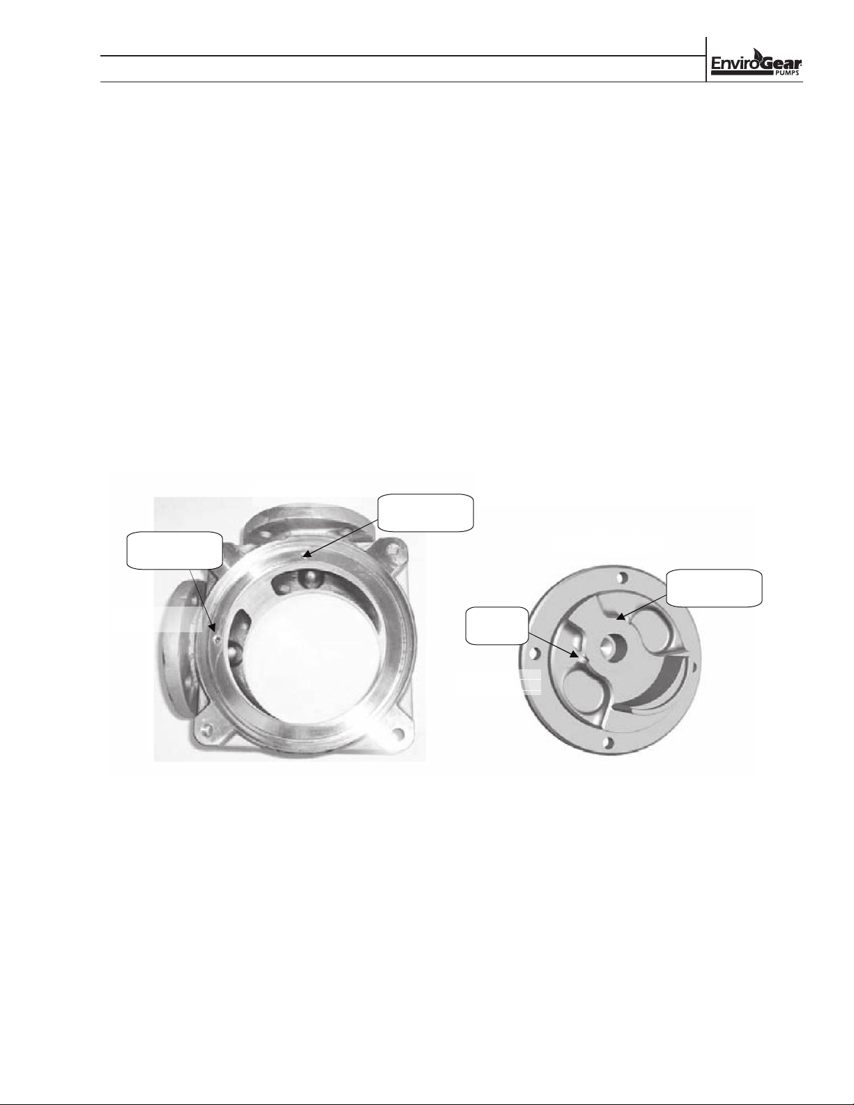
Internal Cooling Circuit
This pump has an internal cooling circuit that circulates some of the pumped fluid through the
magnet chamber. The circuit starts at the discharge port and ends at the suction port. This circuit
h
Note: Consult factory at low differential pressures to ensure proper cooling path circulation.
as three functions:
1. cool the inner magnets,
2. keep fluid in the magnet area from becoming stagnant,
3. lubricate and cool the rotor and idler bushings.
There are special plugs in the casing and head that must be in the correct position to
complete the circuit:
1. The casing needs to be vented on the DISCHARGE side. In some cases,
this is done with an orifice plug that has a hole in it, positioned in the casing hole
behind the DISCHARGE port. In other cases, this is done by leaving the casing hole
behind the DISCHARGE port open.
2. The casing block-off plug is solid (no hole). It belongs in the casing hole behind the
SUCTION port.
3. The head block-off plug is solid (no hole). It is only used in pumps that have no relief
valve, and it belongs in the head hole on the DISCHARGE side.
TECHNICAL INFORMATION
INTERNAL COOLING CIRCUIT
This pump has an internal cooling circuit that
circulates some of the pumped fluid through the
magnet chamber. The circuit starts at the discharge
port and ends at the suction port. This circuit has three
functions:
• Cool the inner magnets
• Keep fluid in the magnet area from becoming
stagnant
• Lubricate and cool the rotor and idler bushings
NOTE: Consult factory at low differential pressures to
ensure proper cooling-path circulation.
There are special plugs in the casing and head that
must be in the correct position to complete the circuit:
1. The casing needs to be vented on the
DISCHARGE side. In some cases, this is
done with an orifice plug that has a hole in
it, positioned in the casing hole behind the
DISCHARGE port. In other cases, this is done by
leaving the casing hole behind the DISCHARGE
port open.
2. The casing block-off plug is solid (no hole). It
belongs in the casing hole behind the SUCTION
port.
3. The head block-off plug is solid (no hole). It is
only used in pumps that have no relief valve, and
it belongs in the head hole on the DISCHARGE
side.
DISCHARGE
Casing block-off
plug (no hole)
Casing orifice
plug (with hole )
DISCHARGE
SUCTION
This hole
left open
SUCTION
Special Cooling Circuit Plugs in Correct Positions
Head block-off
plug (no hole)
ENV-11000-E-04 9 ENVIROGEAR
Page 12
SECTION X
TECHNICAL INFORMATION
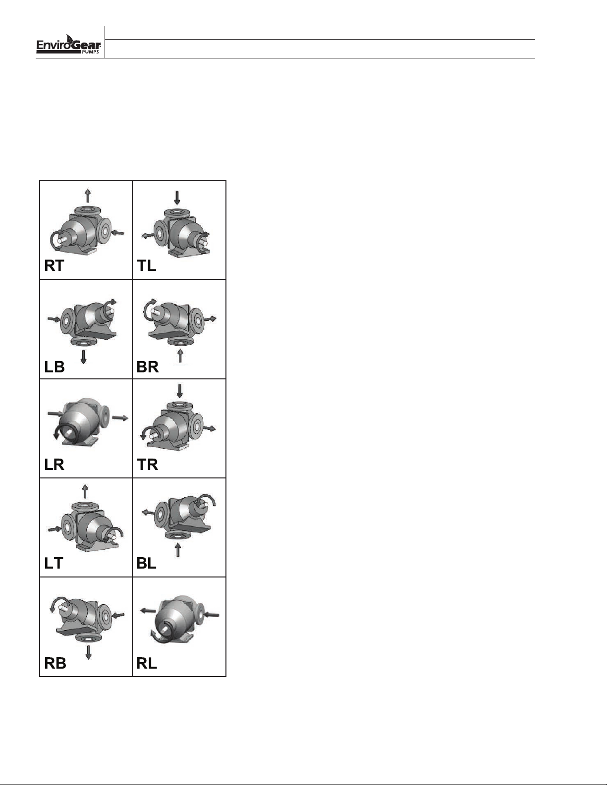
ROTATION AND PORT ORIENTATION
The pump is configured in one of the ten (10) possible
orientations shown inthe table below and it has labels
on it that indicates direction of rotation, suction port
and discharge port.
ENVIROGEAR 10 ENV-11000-E-04
Page 13
–
SECTION 5
SUGGESTED INSTALLATION & OPERATION
E Series gear pumps are designed to meet the
performance requirements of even the most demanding
pumping applications. They have been designed
and manufactured to the highest standards and are
available in a number of different sizes to meet your
pumping needs. Refer to the performance section of
this manual for an in-depth analysis of the performance
characteristics of your pump.
INSTALLATION
Months of careful planning, study and selection efforts
can result in unsatisfactory pump performance if
installation details are left to chance.
Premature failure and long-term dissatisfaction can be
avoided if reasonable care is exercised throughout the
installation process.
LOCATION
Noise, safety and other logistical factors usually
dictate where equipment will be situated on the
production floor. Multiple installations with conflicting
requirements can result in congestion of utility areas,
leaving few choices for additional pumps.
Within the framework of these and other existing
conditions, every pump should be located in such a
way that key factors are balanced against each other to
maximum advantage.
ACCESS
The location of the pumping unit should be accessible.
If it’s easy to reach the pump for maintenance
personnel will have an easier time carrying out routine
inspections and adjustments. Should major repairs
become necessary, ease of access can play a key role
in speeding the repair process and reducing total
downtime.
FOUNDATION
BASEPLATES AND ANCHORS:
The preferred mounting for a baseplate is on a concrete
pad with grouting. No matter how robust the design,
there is always some flexibility in the baseplate itself.
If there is insufficient support under the baseplate, it
can distort causing alignment difficulties and normal
vibrations can be amplified to unacceptable levels
through resonance in the pump support and/or piping.
A properly grouted baseplate will resist distortion and
will provide sufficient mass to dampen any vibration.
NOTE: When pumps and motors are assembled on a
baseplate at the factory, a preliminary alignment is done
to ensure that the pump and motor can be aligned at its
installation. This alignment is not to be considered as a
final alignment. The factory alignment can, and does,
change during shipment and when the pumping unit is
installed. Actually, several alignments are necessary as
will be described later.
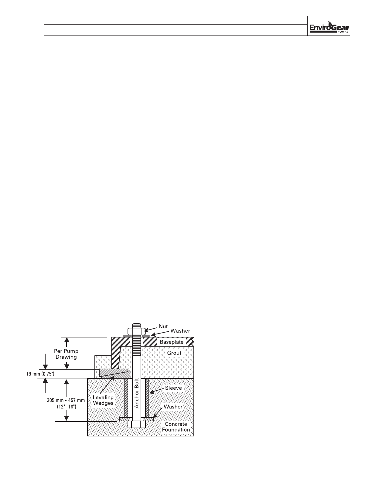
Anchor (foundation) bolts are used to hold the
baseplate to its support structure, whatever that may
be. In the preferred case of mounting the pump unit
on a concrete pad, the anchor bolts are set into the pad
as indicated in the following illustration. When pouring
the pad, it’s helpful to have a wooden template attached
to the foundation form to position the anchor bolts at
their locations as indicated on the pump unit assembly
drawing.
Anchor bolts are usually sized smaller than the
anchor bolt hole size in the base. Calculate bolt
length as indicated in the Figure A on the left.
The ID of the sleeve should be two bolt sizes
larger than the anchor bolt.
Allow approx. 19 mm - 38 mm (3/4" - 1-1/2")
space between the bottom edge of the
baseplate and the foundation for grouting.
A “Sleeve” type anchor bolt is shown here.
Alternatively, a “hook” or “J” type anchor bolt
may be used.
Pack the space between the anchor bolt and
sleeve to prevent concrete and/or grout from
entering this area.
TYPICAL ANCHOR BOLT (SLEEVE TYPE)
ENV-11000-E-04 11 ENVIROGEAR
Page 14

SECTION 4
SUGGESTED INSTALLATION & OPERATION
BASE INSTALLATION AND GROUTING:
NOTE: Before the baseplate is installed, it is advisable to
thoroughly clean the underside to enable the grouting
to adhere to it. Do not use oil-based cleaners since
grout will not bond to it.
Once the concrete pad has cured, the baseplate can be
carefully lowered over the anchor bolts.
Place shims or tapered wedges under the baseplate
at each of the anchor bolt positions to provide about
19 mm - 38 mm (0.75" - 1.50") clearance between the
base and the foundation. Adjust shims/wedges to level
the baseplate. Since there may be some flexibility in
the baseplate, we must perform an initial alignment
prior to grouting to ensure that a final alignment can
be achieved. See section covering Alignment of Pump/
Driver Shafts. Potential problems here include bowing
and/or twisting of the baseplate. If gross misalignment
is observed, shims/wedges may have to be added
under the mid-point of the base or the shims/wedges
at the corners may have to be adjusted to eliminate
any twist. If the driver feet are bolt-bound for horizontal
alignment, it may be necessary to loosen the pump
hold-down bolts and shift the pump and driver to
attain horizontal alignment. When alignment has been
achieved, lightly tighten the anchor bolts. The anchor
bolts should not be fully tightened until the grout has
set.
Grouting furnishes support for the pump unit baseplate
providing rigidity, helping to dampen any vibration and
serves to distribute the weight of the pump unit over the
foundation. To be effective, grouting must completely
fill all voids under the baseplate. For proper adhesion
or bonding, all areas of the baseplate that will be in
contact with the grout should be thoroughly cleaned.
See note above. The grout must be non-shrinking.
Follow the directions of the grout manufacturer for
mixing. Proceed with grouting as follows:
NOTE: If the size of the equipment or the layout of
the installation requires it, grouting can be done in
two steps as long as the first step is allowed to cure
completely before the second step is applied
1. Build a sturdy form on the foundation around the
baseplate to contain the grout.
2. Soak the top of the concrete foundation pad
thoroughly. Remove surface water before pouring.
3. Pour the grout through the hole(s) in the top and/or
through the open ends of the channel steel baseplate,
eliminating air bubbles by tapping, using a vibrator
or pumping the grout into place. If necessary, drill
vent holes into the top of the base to evacuate air.
4. Allow grout to set completely, usually a minimum of
48 hours.
5. Tighten foundation anchor bolts.
6. Recheck alignment to ensure that there have been
no changes.
7. After the grout has dried thoroughly, apply an oil
base paint to shield the grout from air and moisture.
PIPING
Final determination of the pump site should not be
made until the piping challenges of each possible
location have been evaluated. The impact of current
and future installations should be considered ahead of
time to make sure that inadvertent restrictions are not
created for any remaining sites.
The best choice possible will be a site involving the
shortest and straightest hookup of suction and discharge
piping. Unnecessary elbows, bends and fittings should
be avoided. Pipe sizes should be selected to keep
friction losses within practical limits.
All piping should be supported independently of the
pump. In addition, the piping should be aligned to
avoid placing stress on the pump fittings. To eliminate
possible closing of the line when performing pump
maintenance, a gate valve should be installed at the
suction line.
E Series gear pumps are positive displacement pumps;
as such, care must be used in protecting piping and
components used in your system. Pumps equipped
with an internal relief valve are designed to protect the
pump only. A system relief valve should be installed
along with the pump's internal relief valve.
When placing the pump, choose a location as close to
the product source as possible. Care should be taken
in your supply line to avoid cavitation due to viscosity
and suction lift. NOTE: Some liquids may become
thicker with temperature changes. Please refer to your
supplier of product being pumped for information
on viscosity changes due to temperature. Avoid air
pockets on suction side of pump when designing
piping layout. This will also reduce the possibility of
cavitation. The weight of the piping should not be
supported or absorbed by the pump. Suction and
discharge piping should be supported by pipe hangers
or another suitable means.
ENVIROGEAR 12 ENV-11000-E-04
Page 15
SECTION 4
SUGGESTED INSTALLATION & OPERATION
E SERIES GEAR PUMPS ARE NOT SUITED FOR
PUMPING DIRTY, SOLID-LADEN LIQUIDS. A strainer
should be used on the suction side of the pump. The
strainer should consist of an adequate size mesh screen
as to not cause excessive friction loss. It is suggested
that a maintenance program is created to assure that
the inlet strainer remains free of obstructions and
blockage.
ALIGNMENT OF PUMP/DRIVER SHAFTS
WARNING!
NOTE: Driver power must be locked out before
beginning any alignment procedure. Failure to lockout
driver power may result in serious physical injury.
NOTE: Proper alignment is the responsibility of the
installer and user of the equipment.
NOTE: Check alignment if process temperature changes,
piping changes and/or pump service is performed.
Pump and driver shafts need to be aligned for
both parallel and angular alignment. If there is a
misalignment of the shafts, it will place a mechanical
load on the pump and driver shaft/bearing assemblies
as well as the coupling. This will result in vibration,
noise and premature failures.
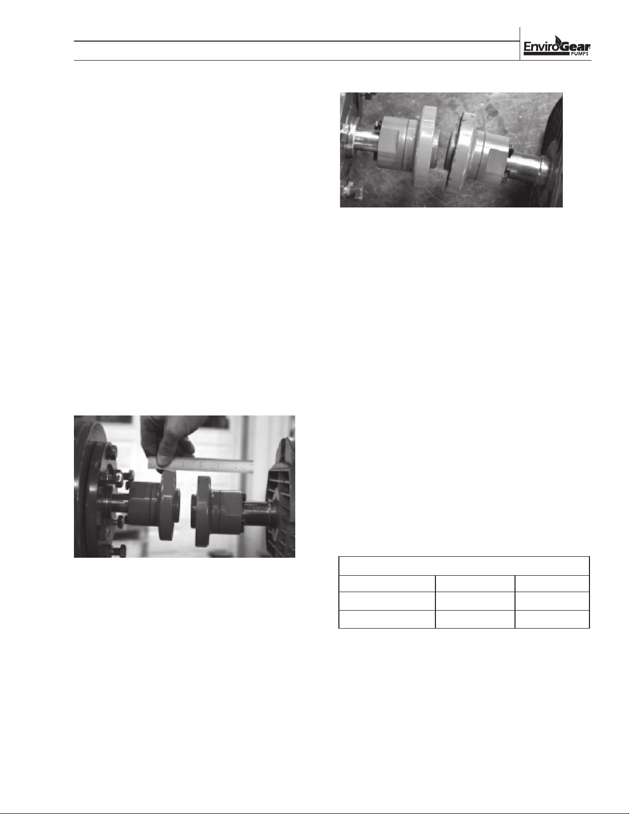
ANGULAR MISALIGNMENT
To bring shafts into alignment, we first need to
determine the amount and direction of both parallel
and angular misalignments. We can then shim and
reposition to correct.
It’s preferable to shim ONLY under the driver feet since
good contact between the pump foot and the base is
necessary to resist any pump flange loading that might
be imposed by the suction and/or discharge piping.
There are three methods commonly used to determine
misalignment:
1. Straight edge and calipers or inside micrometer
(least accurate)
2. Dial indicator (reasonably accurate)
3. Laser alignment equipment; see manufacturer’s
instructions for use
Since any misalignment will impose loads on the pump
and driver shafts, the objective is to minimize any
misalignment in order to protect the pump and driver
and minimize any tendency for vibration. Suggested
misalignment limits are:
For optimum performance and Mean Time Between
Pump Maintenance (MTBPM), use alignment limits half
of those shown above.
PARALLEL MISALIGNMENT
PUMP FRAME GROUP MAX. PARALLEL MAX. ANGULAR
Furthermore, due to the magnetic coupling design of
the E Series pump, misalignment can cause deflection
of the outer ring into the stationary magnet housing
and containment canister. This can cause bearing failure
which, if left undiagnosed, could lead to the outer ring
contacting and potentially breaching the containment
canister.
NOTE: There are design provisions that cause the outer
ring to contact the magnet housing or skid ring prior to
contacting the canister, but this is meant for short term
bearing failure containment, not long-term prevention
of outer ring to canister contact.
ENV-11000-E-04 13 ENVIROGEAR
2/4, 24/32, 55/69, 82 0.005" 0.005"
133/222 0.010" 0.010"
MISALIGNMENT LIMITS
Page 16
SECTION 4
SUGGESTED INSTALLATION & OPERATION
NOTE: In any case, disregard the coupling
manufacturer’s published misalignment limits, as these
will impose unacceptable loads on the pump and motor
shafts and bearings.
Alignment must be done at several different times:
1. Prior to grouting baseplate during installation
2. After grouting baseplate and tightening anchor bolts
3. After attaching suction and discharge piping prior to
initial operation
4. Hot alignment after equipment temperatures have
stabilized
After pump maintenance bearing housing is removed
5.
Since the E Series pump is foot-mounted, its shaft
centerline will rise when handling pumpage at elevated
temperatures. Similarly, the motor shaft centerline will
rise as it reaches its operating temperature. Therefore,
we will often purposely misalign shafts vertically
during cold alignment to allow for thermal growth,
thus bringing the shafts into alignment at operating
temperature. This is shown in the “COLD SETTING OF
PARALLEL VERTICAL ALIGNMENT “ table.
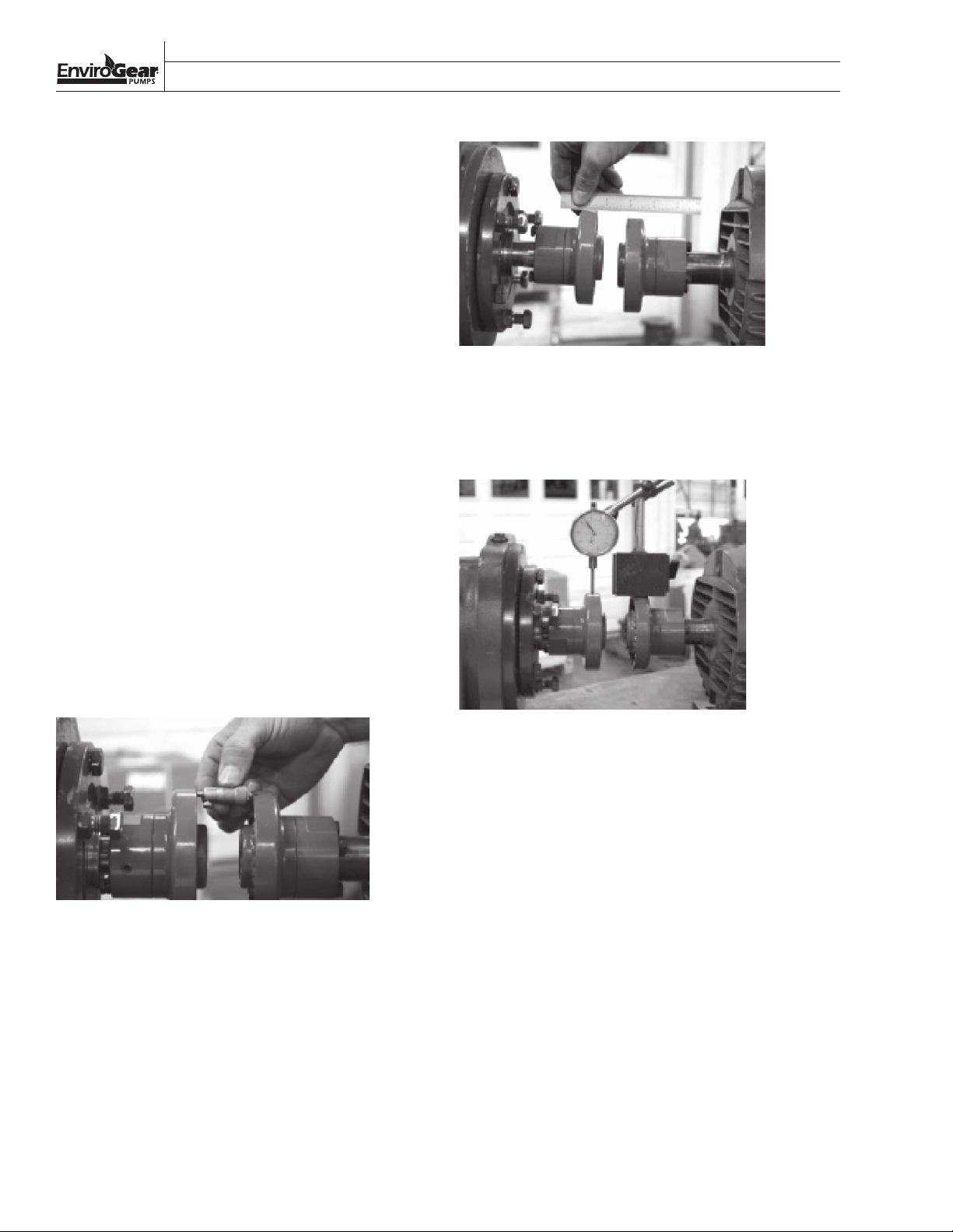
The most simple alignment check is with a straight
edge and calipers or inside micrometer. This method is
the least accurate, but it will serve if a dial indicator or
laser is not available.
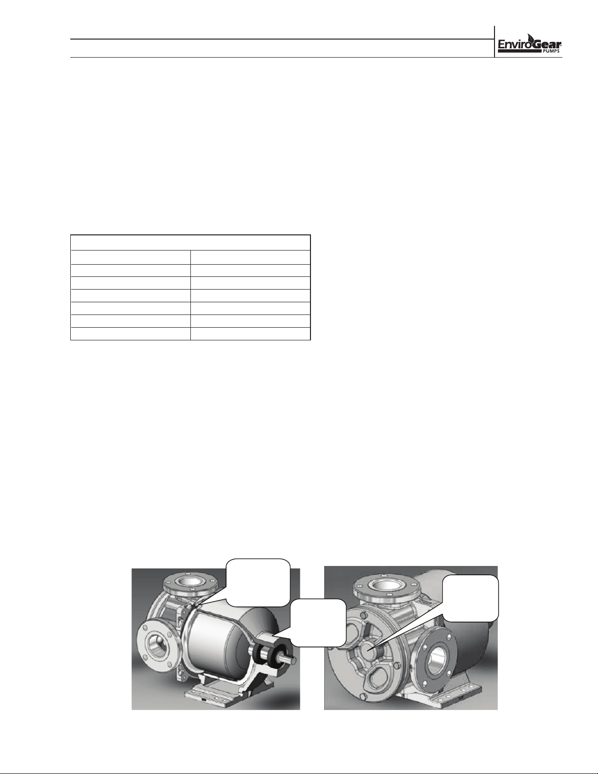
PARALLEL MISALIGNMENT
DIAL INDICATOR METHOD
The dial indicator method is preferred for checking
alignment.
ALIGNMENT WITH STRAIGHT EDGE AND MICROMETER:
ANGULAR ALIGNMENT
With coupling hubs stationary, use inside micrometer
or calipers to measure the gap between the coupling
hubs at 90° intervals. Adjust and/or shim equipment
until the gap difference at all points around the hub(s)
is less than the value shown in the “MISALIGNMENT
LIMITS” table.
With coupling hubs stationary, lay straight edge flat
against rim of coupling hub to determine vertical
and horizontal alignment offsets. Adjust and/or shim
equipment until the straight edge lies flat against
both hub rims, vertical and horizontal.
DIAL INDICATOR SETUP
1. Scribe or mark index lines on both coupling hubs
to indicate where the dial indicator point rests.
2. Set dial indicator to zero.
3. Slowly turn BOTH coupling hubs so that the index
lines match or the indicator point is always on the
mark.
4. Observe dial reading to determine required
adjustments.
5. Acceptable parallel and angular alignment occurs
when the total indicator reading (TIR) for a
complete turn does not exceed the values shown
in the “MISALIGNMENT LIMITS” table.
LASER ALIGNMENT METHOD:
The laser alignment method is preferred for checking
alignment.
Laser alignment is usually the most accurate method.
Follow the laser alignment equipment manufacturer’s
instructions for this method.
ENVIROGEAR 14 ENV-110 00-E-04
Page 17
SECTION X
SUGGESTED INSTALLATION & OPERATION
As previously mentioned, pump and motor shafts
need to be in alignment while they are at their
intended operating temperature. When the shafts
are aligned “cold” (at ambient temperature), we will
intentionally position the motor shaft up or down
in vertical parallel alignment to allow for thermal
growth. Then, when the alignment is checked “hot”
(at stable operating temperature), the shafts should
be confirmed to be in alignment. Use the values in the
following table as starting point for cold alignment
settings. The actual cold alignment setting will be
determined after the hot alignment is performed.
COLD SETTING OF PARALLEL VERTICAL ALIGNMENT
PUMPAGE TEMPERATURE SET DRIVER SHAFT
10°C (50°F) 0.051 mm (0.002") LOW
66°C (150°F) 0.025 mm (0.001") HIGH
121°C (250°F) 0.127 mm (0.005") HIGH
177°C (350°F) 0.229 mm (0.009") HIGH
232°C (450°F) 0.330 mm (0.013") HIGH
260°C (500°F) 0.432 mm (0.017") HIGH
PRESSURE RELIEF VALVES:
• E Series pumps are positive displacement pumps,
which means the system must have provisions for
pressure relief protection, such as a relief valve
mounted directly on the pump or in-line with the
system. Alternatively, the system can be installed
with a torque-limiting device or a rupture disk.
• If the system requires the pump to operate in both
directions, pressure relief protection is required on
both sides of pump.
• When using an integral relief valve, the adjusting
screw cap must always point towards the suction
side of pump. If shaft rotation has to be reversed,
simply remove the pressure relief valve and
reinstall it in the proper configuration to avoid overpressurization of the system.
• Pressure relief valves are not intended to control
pump flow or regulate discharge pressure.
• The pump-mounted integral relief valve should
never be relied upon for system protection.
PUMP CONDITION MONITORING
There are several pump conditions that can be
monitored.
• Canister Temperature: Heat is generated in the
canister when the pump is running because of
moving magnetic fields that pass through it. The
pump has an internal cooling path that pulls heat
away from the canister. If this cooling path is
obstructed, the canister and magnet could become
very hot, which could damage the magnets and/or
canister O-ring.
• The canister temperature can be monitored with a
temperature probe attached to the access port in
the magnet housing near the casing.
• Bearing Vibration: The pump shaft is supported
by rolling-element bearings. The condition of the
bearings can be monitored with a vibration sensor
attached to the magnet housing near the bearings.
• Pumping Chamber Vibration: The pumping gears
rotate with the casing and are supported by journal
bushings. The condition of gears and bushings can
be monitored with a sensor attached to the pump
head.
Location for
Canister
Temperature
Sensor
Location for
Bearing
Vibration
Sensor
Optional Sensor Locations Optional Sensor Locations
ENV-11000-E-04 15 ENVIROGEAR
Location for
Pumping
Chamber
Vibration
Sensor
Page 18

SECTION 4
SUGGESTED INSTALLATION & OPERATION
START UP
• Check to ensure that the pressure/vacuum gauges
are installed on inlet and discharge side of the pump.
• Check to ensure that installation and piping are
correctly fastened and supported.
• Check to ensure that the pump and driver are
properly aligned. Refer to Alignment section.
• Verify that the motor is wired correctly. Check to
ensure that the thermal overload relays are properly
sized and set for operation.
• With motor/driver locked out, check that the pump
rotates by hand.
• Jog motor to validate correct rotation.
• Check to ensure that the coupling guard and all
other safety-related devices and instrumentation are
in place and in working order.
• Check to ensure that the pressure relief valve is
installed correctly.
• Open suction, discharge and any auxiliary valves,
such as in-line PRV loops, to ensure proper flow into
and out of pump.
• Prime pumping chamber if possible.
• If pump handles pumpage at temperature greater
than 93°C (200°F), the pump should be gradually
warmed until its temperature is within 38°C (100°F)
of intended operating temperature.
• Start pump. If flow is not achieved in 30 seconds shutoff immediately. “Dry” running a pump for extended
periods of time will damage the pump. If fluid does
not start to flow in 30 seconds, revisit the previous
steps. If every step has been followed, manually fill
the pump with the process fluid or a lubricating fluid
compatible with the process and restart the pump. If
no fluid is flowing within 30 seconds shut the pump
down and proceed to trouble shooting section of
this document.
• Once pump is operational, listen for any untoward
noise, check for any significant vibration or
indications of binding. If any of these are observed,
the pump should be stopped immediately and a
thorough check of the installation should be made
to determine the cause. Correct any fault(s) prior to
re-starting the pump.
ENVIROGEAR 16 ENV-11000-E-04
Page 19
SECTION 6
PUMP ADJUSTMENTS AND MAINTENANCE
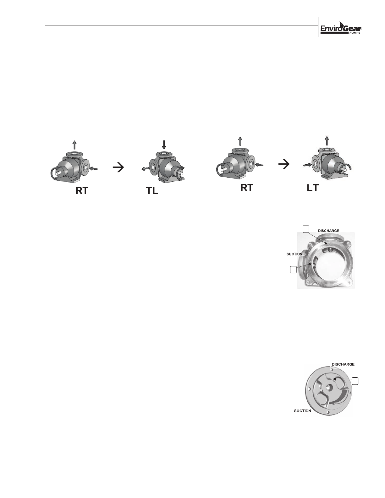
CHANGING PORT ORIENTATION ONLY
(Shaft Rotation Unchanged)
The following instructions apply for changes when
the direction of shaft rotation will not change, such
as changing from RT to TL. Since the shaft rotation
is unchanged, the discharge and suction positions
relative to the casing and head will not change and,
therefore, the cooling circuit plugs will not be moved.
See Internal Cooling Circuit in Section 4.
Port Orientation Change When Shaft
Rotation Does Not Change
If the pump is equipped with a relief valve,
disassemble the relief valve per the instructions in
Section 7, Pump Disassembly & Repair Processes.
For E1-24, E1-32, E1-55, E1-69 , E1-82, E1-133 and
E1-222 models, the relief valve does not need to be
disassembled; leave the relief valve attached to the
head.
Disassemble the pumping chamber per the instructions
in Section 7, Pump Disassembly & Repair Processes.
Assemble pumping chamber in the new orientation
per the instructions in Section 7, Pump Disassembly &
Repair Processes.
CHANGING PORT ORIENTATION AND
SHAFT ROTATION
The following instructions apply for changes when
the direction of shaft rotation will change, such as
changing from RT to LT. Since the shaft rotation will
change, the discharge and suction positions relative to
the casing and head will also change and, therefore,
the cooling circuit plugs will be moved. See Internal
Cooling Circuit in Section 4.
Port Orientation Change When Shaft
Rotation Change
1. If the pump is
equipped with a relief
valve, disassemble
the relief valve per
the instructions
in Section 7,
Pump
Disassembly & Repair
Processes.
2. Disassemble
pumping chamber per the instructions in Section
7, Pump Disassembly & Repair Processes.
3. Remove the casing orifice plug (not found on all
11
12
Casing Plugs
configurations) and casing block-off plug.
If the pump is equipped with a relief valve, assemble
relief valve per the instructions in Section 7, Pump
Disassembly & Repair Processes.
4. Install the casing orifice plug (if required) behind
the DISCHARGE port.
5. If the pump is equipped
with a head block-off
plug, move it to the
DISCHARGE side.
14
6. Assemble pumping
chamber in the new
orientation per the
instructions in Section
7, Pump Disassembly &
Head Block-Off Plug
Repair Processes.
7. If the pump is equipped with a relief valve,
assemble relief valve in the new orientation per
instructions in Section 7, Pump Disassembly &
Repair Processes.
ENV-11000-E-04 17 ENVIROGEAR
Page 20

SECTION X
PUMP ADJUSTMENTS AND MAINTENANCE
CHANGING RELIEF VALVE
PRESSURE SETTING
(E1-2 thru E1-82 Models)
In order to maintain the integrity of the relief valve
setting, the E1-2 thru E1-82 E Series relief valves
are not externally adjustable. Instead, the setting is
adjusted by changing the poppet and spring.
1. Obtain a new poppet and spring for the desired
relief-valve setting.
2. Disassemble relief valve per the instructions
in Section 7, Pump Disassembly & Repair
Processes.
3. Reassemble the relief valve using the new
poppet and spring per the instructions in Section
7, Pump Disassembly & Repair Processes.
CHANGING RELIEF VALVE
PRESSURE SETTING
(E1-133 and E1-222 Models)
1. Carefully remove the valve cap covering the
adjusting screw.
2. Loosen the adjusting screw lock nut.
3. Install a pressure gauge in the discharge line.
4. Turn the adjusting screw inward (clockwise)
to increase pressure and outward (counterclockwise) to decrease pressure.
5. With the discharge line valve closed (at a point
beyond the pressure gauge), the gauge will show
the maximum pressure (that the pressure relief
valve will allow) while the pump is in operation.
ENVIROGEAR 18 ENV-11000-E-04
Page 21

SECTION 7
PUMP DISASSEMBLY & REPAIR PROCESS
RELIEF VALVE DISASSEMBLY
(E1-2 thru-E1-82 Models)
1. Remove the screws that hold the valve body to
the head. It is normal for the valve spring to push
the valve body away from the head during this
step; spring must be fully relaxed before the
screws are fully removed.
2. Remove the valve body, spring, poppet and
O-ring.
RELIEF VALVE DISASSEMBLY
(E1-133 and E1-222 Models)
1. Place a mark on the valve and head prior
to disassembly in order to ensure proper
reassembly.
2. Remove the pressure relief valve cap.
3. Measure and record the extension length of the
adjusting screw.
4. Loosen the pressure relief valve lock nut and
then back out pressure relief valve bonnet and
adjusting screw until the spring pressure is
released.
5. Remove, clean and inspect all parts (i.e., bonnet,
spring guide, spring and poppet) for wear or
damage and replace as needed.
ENV-11000-E-04 19 ENVIROGEAR
Page 22
00
1
SECTION X
PUMP DISASSEMBLY & REPAIR PROCESS
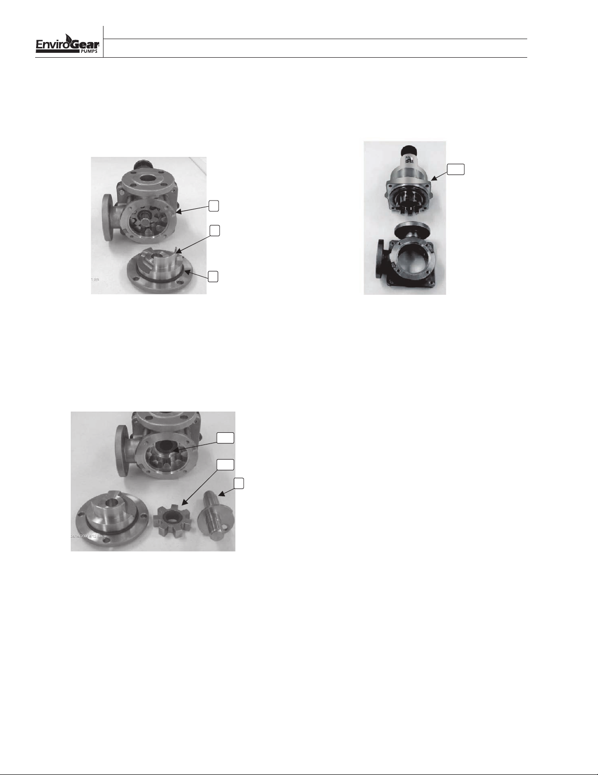
PUMPING CHAMBER DISASSEMBLY
1. Remove the screws that hold the head to the
casing.
2. Remove the head.
2
1
5
Remove Head
NOTE: When the head or spindle is removed, the
pump will be difficult to turn by hand.
3. Remove the head O-ring from the head.
6. Remove the screws that hold the outer drive
assembly to the casing.
7. Separate the casing and outer drive assembly.
100
Remove Casing
8. Remove the canister O-ring from its groove in
the casing.
4. Remove the idler assembly by sliding it of f the
spindle.
200
300
3
Remove Idler and Spindle
5. Pull the spindle out of the rotor assembly.
ENVIROGEAR 20 ENV-11000-E-04
Page 23
SECTION X
6
7
20
0
Tool
F-00097
PUMP DISASSEMBLY & REPAIR PROCESS
REMOVE ROTOR ASSEMBLY FROM
OUTER DRIVE ASSEMBLY
(E1-2 and E1-4 Models)
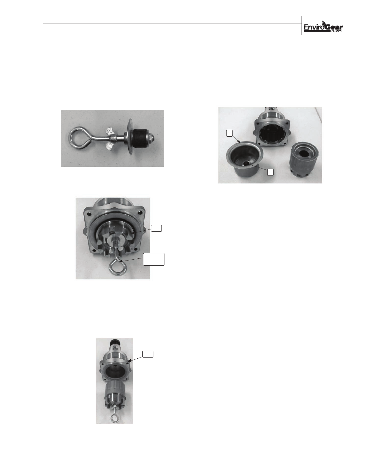
1. Use tool F-00097 to firmly grab the rotor
assembly in the bushing bore area.
Pump Disassembly Tool F-00097
200
3. Remove the tool and set the rotor assembly
aside, away from any magnetic material (e.g.,
steel, iron).
4. Remove the canister that contains the support
plate from the outer drive assembly.
6
7
Canister Removed
Tool
F-00097
Tool Inserted in Rotor Assembly
2. Pull the rotor assembly out of the outer drive
assembly using moderate force of 18 to 27 kg
(40 to 60 lb).
100
1
Drive Assembly
ENV-11000-E-04 21 ENVIROGEAR
Page 24
SECTION X
7
PUMP DISASSEMBLY & REPAIR PROCESS
REMOVE ROTOR ASSEMBLY FROM
OUTER DRIVE ASSEMBLY
(E1-24, E1-32, E1-55, E1-69 and E1-82 Models)
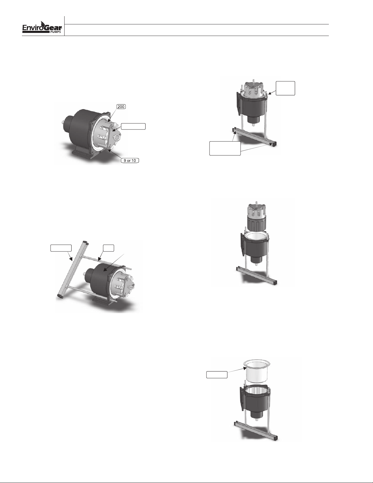
1. Attach the puller plate to the rotor assembly
using three of the pump’s 12.7 mm (1/2”) screws.
200
Wing Nut
9 or 10
Attach Puller Plate
2. Loosely fit the two rods into opposite holes on
the outer drive assembly.
3. Loosely position the two rod ends into the
channel.
4. Twist the two rods to tighten the channel nuts
that lock the rods to the channel.
7. Firmly affix the channel to the workbench
surface so it can safely resist a lifting force of up
to 182 kg (400 lb).
Puller
Plate
Firmly affix
to workbench
Tool Fully Assembled
8. Slowly pull the rotor assembly up and away from
the drive assembly using a crane, hoist or other
suitable lifting device.
Channel
Attach Rods and Channel
Rod
5. Assemble the two wing nuts onto the two rods
to hold them to the outer drive assembly.
6. Carefully lift the outer drive assembly (with
the tool kit attached) and set it on a suitable
workbench vertically with the rotor teeth
facing up.
Pull Rotor Assembly Up
9. Remove the puller plate and set the rotor
assembly aside, away from any magnetic
material (e.g., steel, iron).
10. Remove the canister containing the support
plate from the outer drive assembly.
6 & 7
Remove Canister
ENVIROGEAR 22 ENV-11000-E-04
Page 25
PUMP DISASSEMBLY & REPAIR PROCESS
REMOVE ROTOR ASSEMBLY FROM
OUTER DRIVE ASSEMBLY
(E1-133 and E1-222 Models)
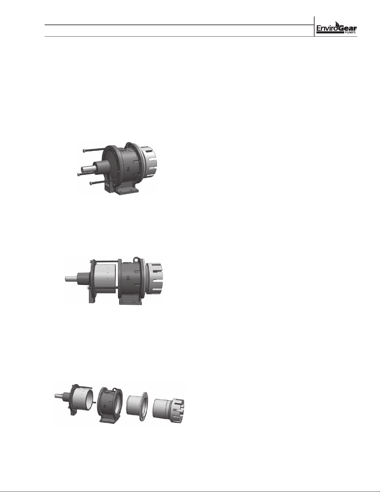
1. Remove (6) screws holding the bearing housing
to the magnet housing.
2. Remove (3) jack screws from their storage
location in the bearing housing foot.
3. Loosely install jack screws into the bearing
housing.
SECTION X
Install Jack Screws
4. Slowly and evenly thread the jack screws into
the magnet housing, which will separate the
bearing housing and the magnet housing.
5. Continue until the coupling has separated.
Separate Coupling with Jack Screws
6. Remove the rotor assembly from the front of
the mag housing and set aside, away from any
magnetic material (e.g., steel, iron). Use the three
threaded holes on the ends of the rotor teeth as
needed.
7. Remove the canister from the magnet housing.
Remove Rotor and Canister
ENV-11000-E-04 23 ENVIROGEAR
Page 26
SECTION X
PUMP DISASSEMBLY & REPAIR PROCESS
REPLACE IDLER BUSHINGS
Carbon-Graphite and Bronze
(Consult Factory for Other Bushing Materials)
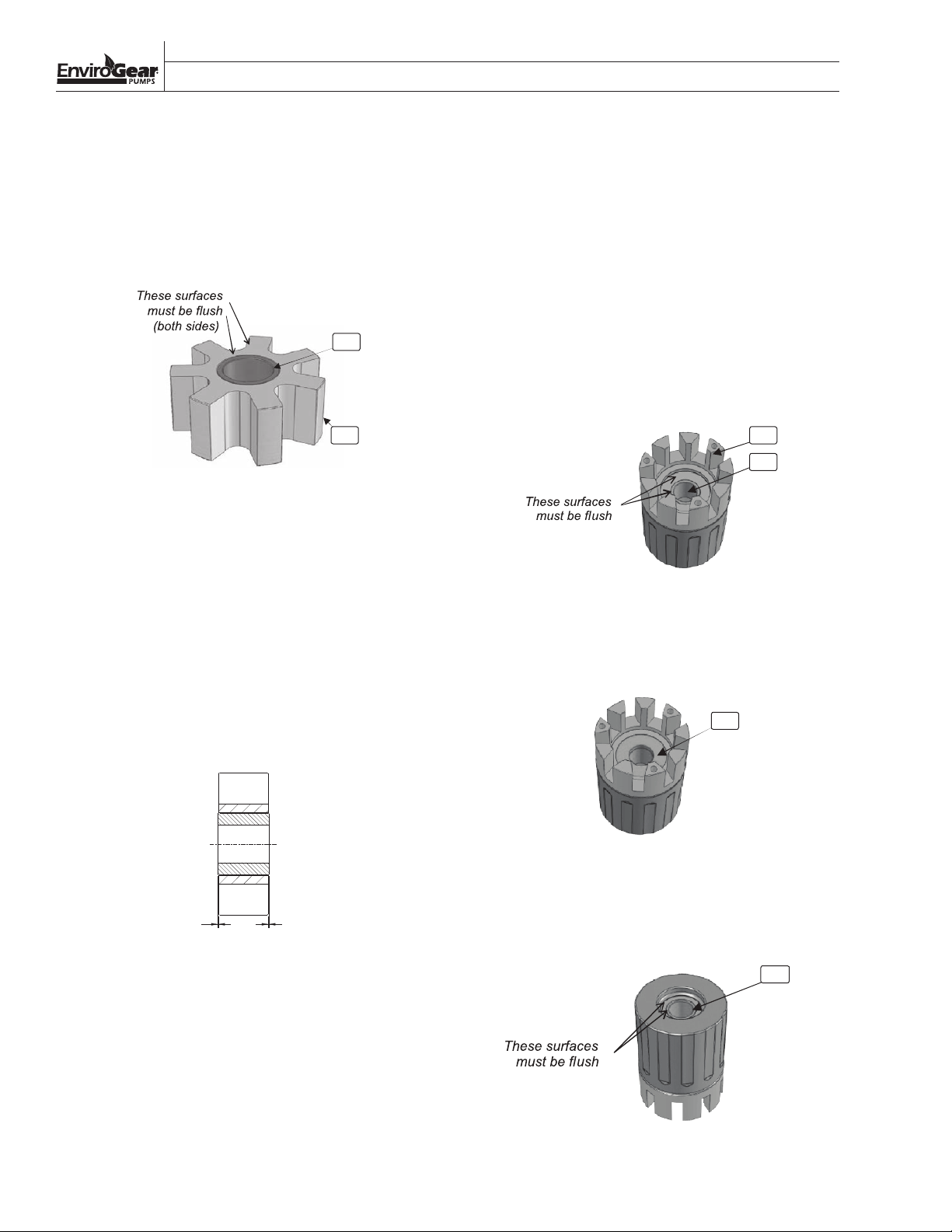
1. Remove the old bushing by pressing it out of
the idler. It is not unusual for carbon graphite
bushings to crack or break apart during removal.
302
301 201
Assemble Idler
2. Inspect the idler bore for any damage. Any small
scratches or nicks must be filed smooth before
installing the new bushing
3. Press the new idler bushing into the idler leading
with the tapered edge.
REPLACE ROTOR BUSHINGS
Carbon-Graphite and Bronze
(E1-2 thru E1-82 Models)
1. Remove the old bushings by pressing them out
of the rotor. It is not unusual for the bushings to
crack or break apart during removal.
2. Inspect the rotor bore for any damage. Any small
scratches or nicks must be filed smooth before
installing the new bushings.
3. Press the front radial bushing into the rotor,
leading with the tapered edge. The bushing is
in its proper location when the front face of the
bushing is flush with the nearest rotor face.
208
Install Front Radial Bushing
a. For models E1-2 thru E1-82, the bushing is
in its proper location when both ends of the
bushing are flush or slightly recessed from the
idler face.
b. For models E1-133 and E1-222, the bushings
should protrude per the sketch.
.004
.002
IDLER BUSHING PROTRUSION
(E1-133 and E1-222 Models)
.004
.002
4. Press the thrust bushing into the rotor, leading
with the tapered edge, until it bottoms out
207
207
Install Thrust Bushing
.
5. Press the rear radial bushing into the rotor,
leading with the tapered edge. The bushing is
in its proper location when the rear face of the
bushing is flush with the nearest rotor face.
208
Install Rear Radial Bushing
ENVIROGEAR 24 ENV-11000-E-04
Page 27
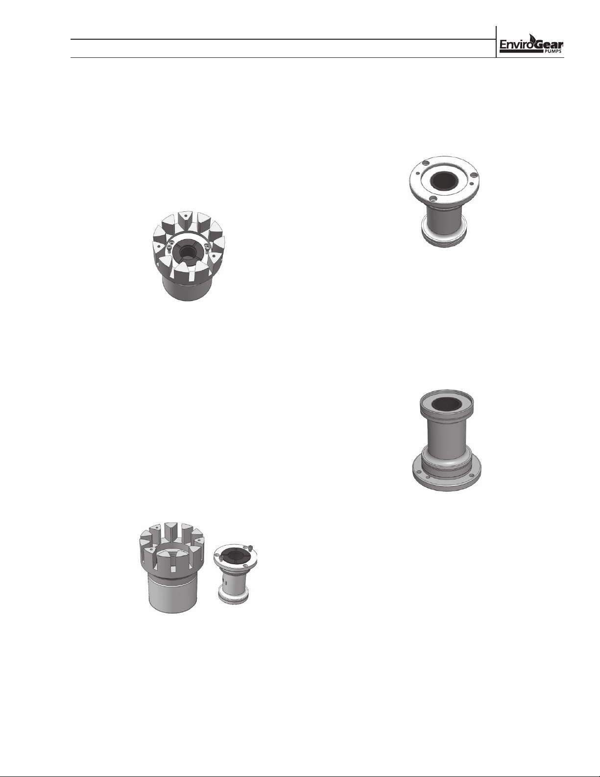
SECTION X
PUMP DISASSEMBLY & REPAIR PROCESS
REPLACE ROTOR BUSHINGS
Carbon-Graphite and Bronze
(E1-133 and E1-222 Models)
NOTE: The bushing carrier and rotor head are fitted
together with a light interference fit.
1. Remove the three bushing carrier bolts.
2. Loosely install the bushing carrier bolts into the
two jacking screw holes in the bushing carrier.
Install Jack Srews
3. Slowly and evenly thread the bushing carrier bolts
into the bushing carrier, which will separate the
bushing carrier from the rotor head.
4. Continue until the bushing carrier is free of the
interference fit
.
8. Press the front radial bushing into the bushing
carrier, leading with the tapered edge. The bushing
is in its proper location when the front face of the
bushing is flush with the nearest bushing carrier
face.
Install Front Radial Bushing
9. Press the front thrust bushing into the bushing
carrier, leading with the tapered edge, until it
bottoms out.
10. Press the rear radial bushing into the bushing
carrier, leading with the tapered edge. The bushing
is in its proper location when the rear face of the
bushing is flush with the nearest bushing carrier
face.
5. Separate the bushing carrier from the rotor.
WARNING: By removing the bushing carrier, the
inner ring and rotor head are no longer fastened
together. Do not attempt to lift the rotor assembly
(inner ring and rotor head) by way of the rotor
head when the bushing carrier is not securely
fastened in place. If an attempt is made to lift
the rotor assembly without the bushing carrier
installed, the inner ring will separate from the
rotor head and potentially cause injury.
Remove Bushing Carrier
6. Remove the old bushings by pressing them out
of the bushing carrier. It is not unusual for carbon
graphite bushings to crack or break apart during
removal.
7. Inspect the bushing carrier bore and rotor assembly
bore for any damage. Any small scratches or nicks
must be filed smooth before installing the new
bushings and reassembling the rotor.
Install Rear Radial Bushing
11. Press the rear thrust bushing into the bushing
carrier, leading with the tapered edge, until it
bottoms out.
12. Loosely install bushing carrier back into the rotor
assembly.
13. The connection between the bushing carrier and
the rotor head is a slight interference fit. Insert the
3 bushing carrier bolts and evenly tighten them in
small increments to pull the bushing carrier into
the rotor head. Extreme caution must be taken to
ensure the bushing carrier is properly aligned in
the rotor assembly before tightening the bushing
carrier bolts.
14. Torque bushing carrier bolts to 58 N•m (43 ft-lb)
for cast iron and carbon steel pumps, and 50 N•m
(37 ft-lb) for stainless steel pumps.
ENV-11000-E-04 25 ENVIROGEAR
Page 28
SECTION X
102 106 105 108
10
5
D
PUMP DISASSEMBLY & REPAIR PROCESS
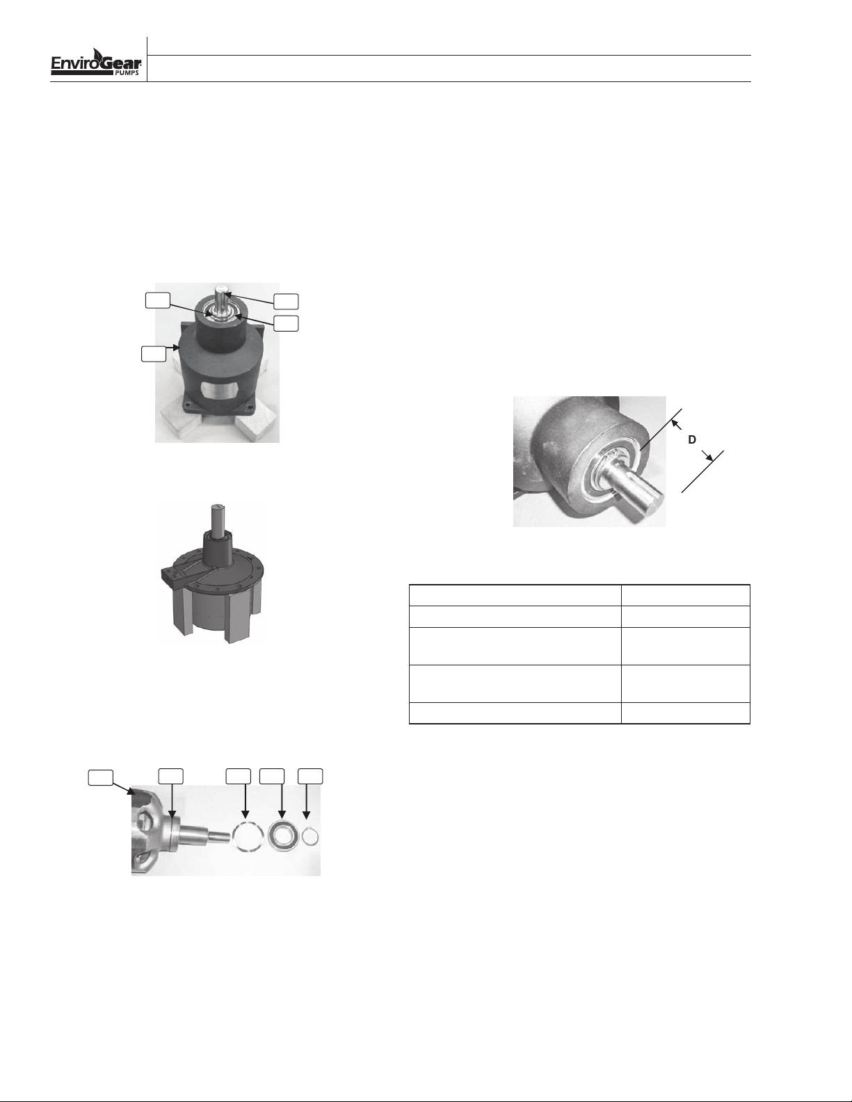
REPLACE OUTER BALL BEARING
1. Position the outer drive assembly on blocks in a
suitable press with the shaft facing upward.
2. Remove the snap ring from its groove in the
shaft.
3. Press the shaft downward until the outer bearing
disengages from the shaft.
108
100
Outer Drive Assembly on Blocks
(E1-2 thru E1-82 Models)
103
105
6. Apply a light oil to the shaf t and press the new
inner bearing into the shaft. The new bearing
inner race should be flush with the outer ring.
Be careful to avoid disrupting the shaft position
relative to the outer ring.
7. Insert the wave spring into the inner bearing
counter-bore of the magnet housing /bearing
housing.
8. Insert the outer ring/shaft/inner bearing
assembly into the magnet housing/bearing
housing.
9. Press the outer bearing onto the shaft until the
distance from the end of the shaft to the face of
the bearing meets the following specifications:
Outer Drive Assembly on Blocks
(E1-133 and E1-222 Models)
4. Remove the outer ring assembly with shaft and
inner bearing attached, wave spring and outer
bearing.
102
105 10 6 10 5 108
Bearing Area Components
5. Remove the inner bearing from the shaft with a
suitable gear puller.
Outer Bearing Location
Model Distance (D)
E1-2, E1-4 48.2 mm (1.9”)
E1-24, E1-32, E1-55, E1-69,
64.4 mm (2.5”)
E1-82 [1.125" Shaft]
E1-24, E1-32, E1-55, E1-69, E1-82
99.3 mm (3.9”)
[1.437" Shaft]
E1-133, E1-222 124.5 mm (4.9")
10. Install the snap ring in its groove in the shaft.
ENVIROGEAR 26 ENV-11000-E-04
Page 29
SECTION X
PUMP DISASSEMBLY & REPAIR PROCESS
REPLACE INNER MAGNETS
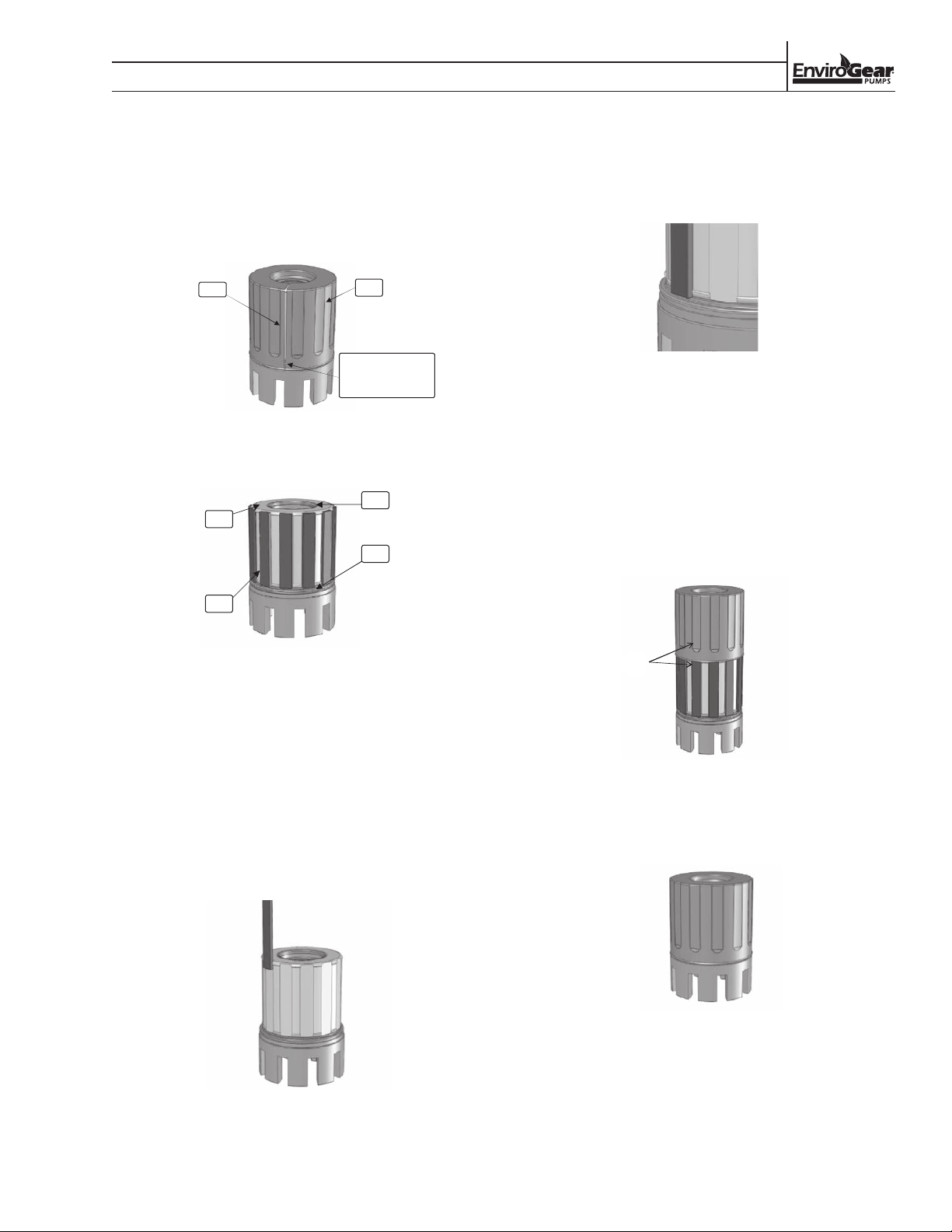
(E1-2 thru-E1-82 Models)
1. Carefully cut the sleeve. Be careful to avoid
damaging the rotor in the area around the front
O-ring.
Cut
Cut Sleeve
2. Pull sleeve off of the rotor assembly.
202
204
Do not damage
rotor in the front
O-ring area.
205
206
7. Slide the magnet segment along the length of
the inner ring until it touches the small stop
at the end of the inner ring. Refer to the Inner
Magnet Polarity figure on page 28.
Proper Magnet Position
8. Repeat steps 6 and 7 for the other magnet
segments, making sure that each magnet is in
opposite polarity with adjacent magnets.
9. Align the new sleeve over the back of the rotor
such that the sleeve indentations are lined up
with the magnets.
10. Press the sleeve over the magnets and O-rings
until it contacts the rear of the inner ring.
203
Remove Sleeve
3. Remove the old magnet segments from the inner
ring.
4. Remove the front and rear sleeve O-rings from
the grooves in the rotor.
5. Install new O-rings in the grooves of the rotor.
6. Slowly bring one end of the new magnet
segment into contact with the end of one flat on
the inner ring, such that only a short length of
the magnet is in contact with the inner ring.
Aligned
Proper Sleeve Alignment
11. Visually inspect the front and rear of the sleeve to
verify that the O-rings were not damaged by the
sleeve.
Rotor Assembly
Assemble Magnet Segments
ENV-11000-E-04 27 ENVIROGEAR
Page 30
SECTION X
PUMP DISASSEMBLY & REPAIR PROCESS
REPLACE INNER MAGNETS
(E1-133 and E1-222 Models)
1. Carefully cut the sleeve. Be careful to avoid
damaging the rotor in the area around the front
and rear O-rings.
2. If bushing carrier is installed, remove it per
the instructions in Section 7, Replace Rotor
Bushings.
3. Remove the rotor head. If it doesn’t come off
freely, then thread the bushing carrier bolts into
the jacking screw holes on the rotor crown and
slowly remove the rotor crown from the inner
ring by evenly tightening the jacking screws.
4. Pull sleeve off of the rotor assembly.
5. Remove the old magnet segments from the
vinner ring.
6. Remove the front and rear sleeve O-rings from
the grooves in the inner ring.
7. Slowly bring one end of the new magnet
segment into contact with the end of one flat on
the inner ring, such that only a short length of
the magnet is in contact with the inner ring.
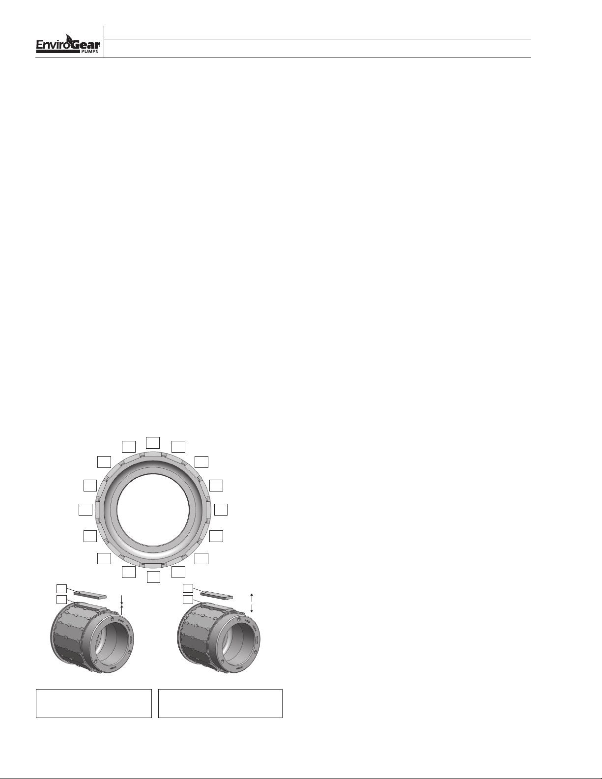
9. Repeat steps 7 and 8 for the other magnet
segments, making sure that each magnet is in
opposite polarity with adjacent magnets. Refer
to the Inner Magnet Polarity figure.
10. Install new O-rings in the grooves of the
inner ring.
11. Align the new sleeve over the front of the inner
ring and press the sleeve over the magnets and
O-rings until it contacts the front of the inner
ring.
12. Visually inspect the front and rear of the sleeve
to verify that the O-rings were not damaged by
the sleeve.
13. Install rotor crown onto inner ring.
14. Install bushing carrier into rotor assembly per
the instructions in Section 7, Replace Rotor
Bushings.
8. Slide the magnet segment along the length of
the inner ring until it touches the small stop at
the end of the inner ring.
N
SS
N N
S
N N
SS
N
N
N
NOTE: E1-133/222 inner ring shown NOTE: E1-133/222 inner ring shown
S
NN
SS
S
N
Check orientation: same
polarity = attraction force
Check orientation: opposite
polarity = repulsion force
Inner Magnet Polarity
ENVIROGEAR 28 ENV-11000-E-04
Page 31
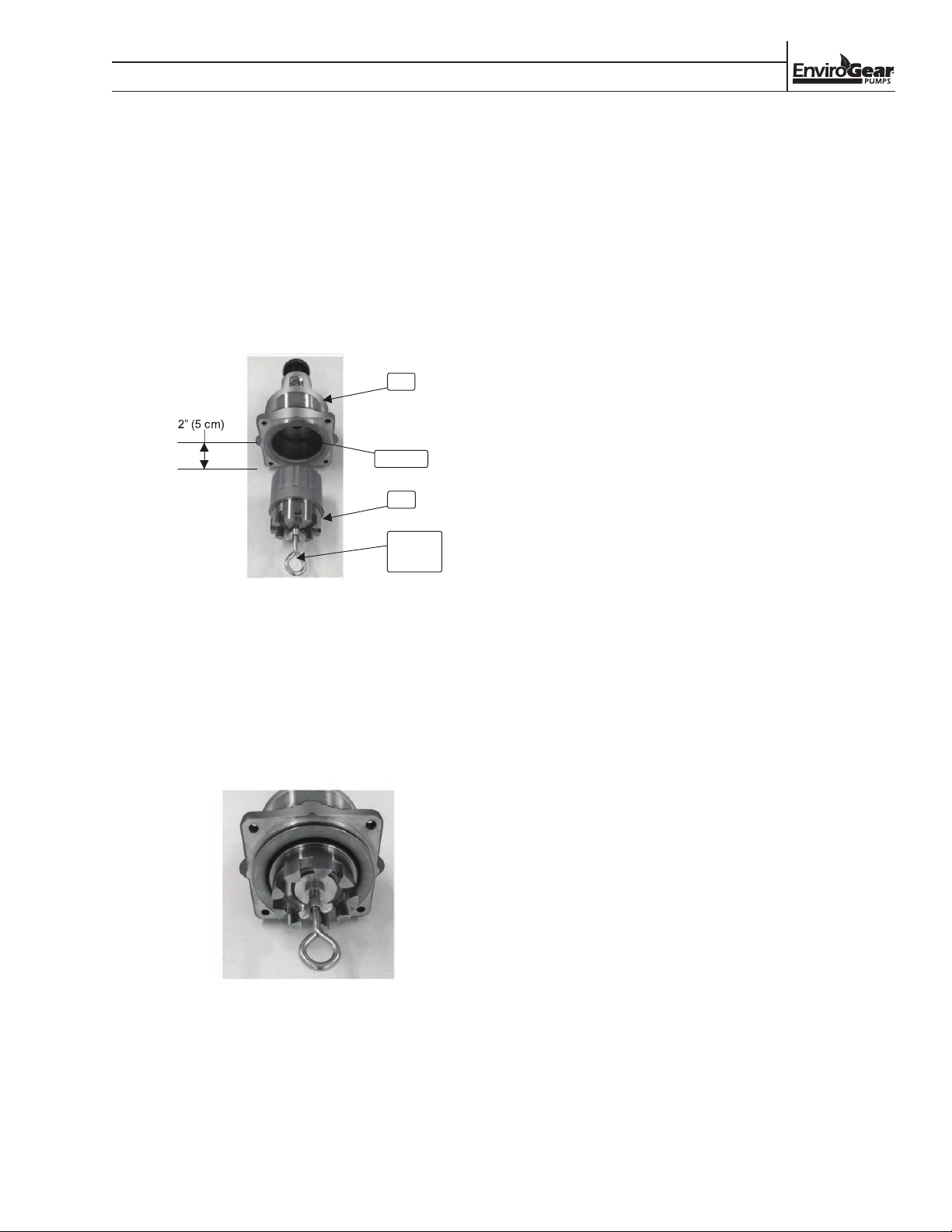
PUMP DISASSEMBLY & REPAIR PROCESS
INSTALL ROTOR ASSEMBLY INTO OUTER
DRIVE ASSEMBLY
(E1-2 and E1-4 Models)
1. Insert the canister and support plate into the
outer drive assembly. The support plate has no
“top” and “bottom.” Therefore, its orientation is
irrelevant.
2. Use Tool F-00097 to firmly grab the rotor
assembly in the bushing bore area.
100
6 & 7
100
SECTION X
Tool
F-00097
Tool in Rotor Assembly
3. Bring the rotor assembly toward the canister
until the back of the rotor is about 5 cm (2”) from
the front of the outer drive assembly.
4. Slowly let the outer magnets pull the rotor into
the canister while using moderate resisting force
of about 18 to 27 kg (40 to 60 lb).
5. Remove the puller tool.
Rotor Assembly in Place
ENV-11000-E-04 29 ENVIROGEAR
Page 32
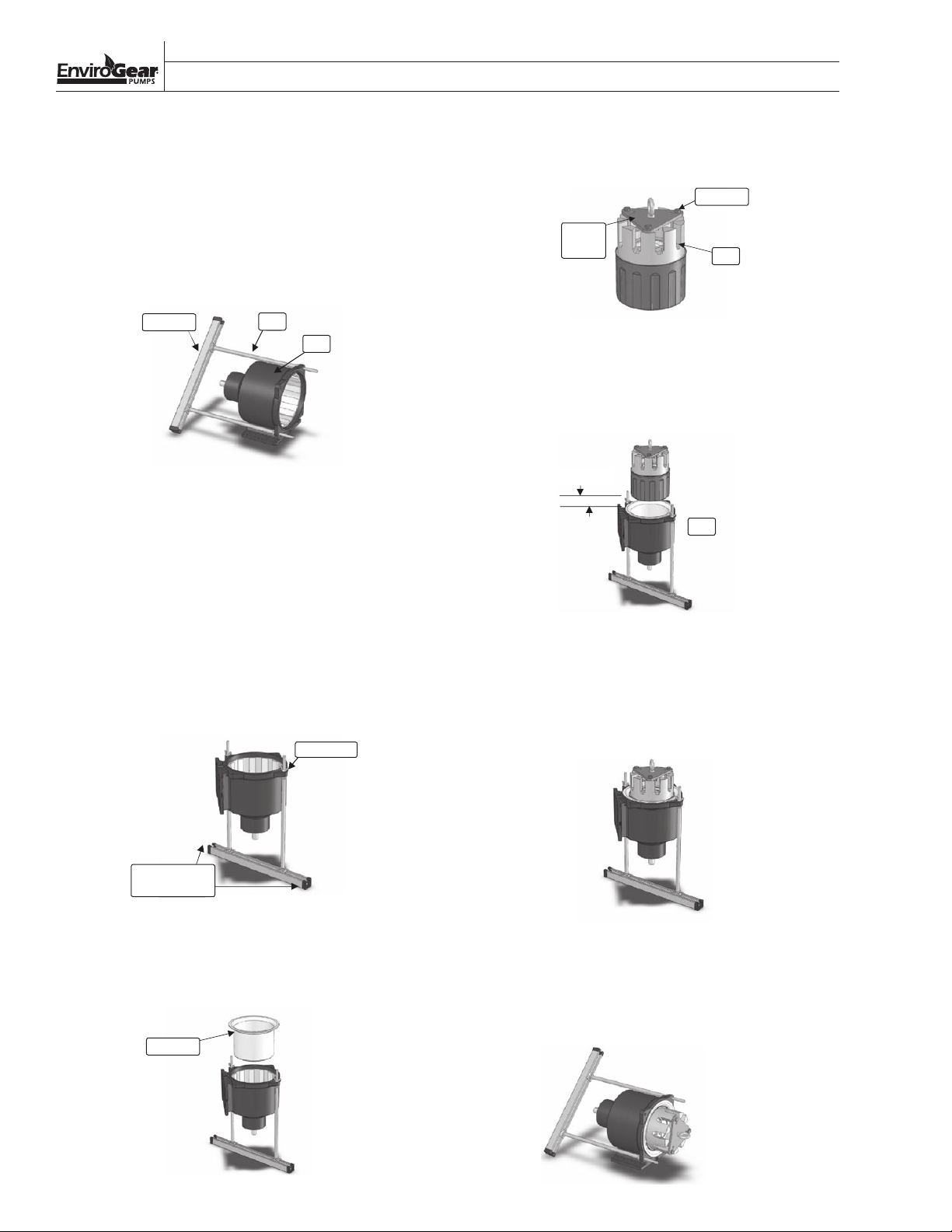
SECTION X
PUMP DISASSEMBLY & REPAIR PROCESS
INSTALL ROTOR ASSEMBLY INTO OUTER
DRIVE ASSEMBLY
(E1-24, E1-32, E1-55, E1-69 and E1-82 Models)
1. Loosely fit the two rods into opposite holes on
the outer drive assembly.
2. Loosely position the two rod ends into the
channel.
Channel
Assemble Rods and Channel
3. Twist the two rods to tighten the channel nuts
and clamp the rods to the channel.
4. Assemble the two wing nuts onto the two rods
to hold them to the outer drive assembly.
5. Carefully lift the outer drive assembly (with tool
kit attached) and set it vertically on a suitable
workbench with the rotating teeth facing
upwards.
6. Firmly affix the channel to the workbench
surface, so that it can safely resist a lifting force
of up to 182 kg (400 lb).
Rod
100
Wing Nut
8. Attach the puller plate to the rotor assembly
using three of the pump’s 13 mm (1/2”) screws.
9 or 10
Puller
Plate
Puller Plate on Rotor Assembly
200
9. Support the rotor assembly using a crane, hoist
or other suitable lifting device, and position it
above the canister 10 cm (4”) from the front of
the outer drive assembly.
10 cm (4")
100
Rotor Assembly Ready for Lowering
10. Slowly lower the rotor assembly into the
canis ter. NOTE: During this process, the inner
magnets on the rotor assembly will be strongly
attracted to the outer magnets in the outer drive
assembly.
Firmly affix to
workbench
Outer Drive Assembly Mounted to Tool
Rotor Assembly in Place
7. Insert the canister containing the support plate
into the outer drive assembly. The support
plate has no “top” or “bottom.” Therefore, the
orientation is irrelevant.
11. Carefully lift the outer drive assembly (with the
tool kit attached) and set it on a workbench,
resting on the pump’s foot.
12. Remove the tool rods and puller plate.
6 & 7
Insert Canister and
Support Plate
ENVIROGEAR 30 ENV-1100 0-E-04
Remove Tool
Page 33
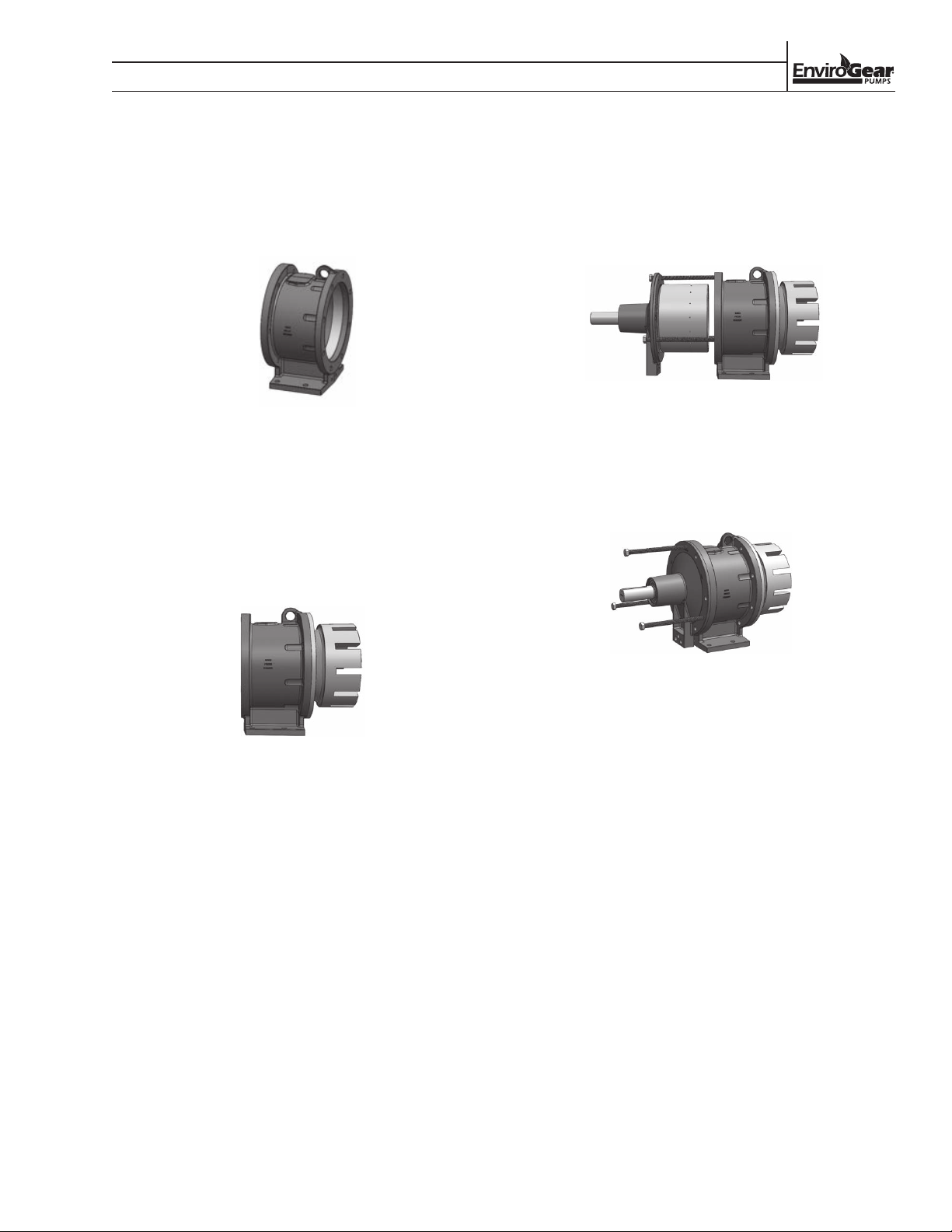
SECTION X
PUMP DISASSEMBLY & REPAIR PROCESS
INSTALL ROTOR ASSEMBLY INTO OUTER
DRIVE ASSEMBLY
(E1-133 and E1-222 Models)
1. Secure the magnet housing firmly to a level
surface.
Mag Housing on Level Surface
2. Install the canister into the magnet housing
aligning the bolt holes. Orientation is irrelevant.
3. Install the rotor assembly into the canister,
ensuring it is all the way seated into the rear of
the canister. A block may be required under the
rotor head to ensure it stays parallel with the
build surface during the following steps.
5. Orient the outer drive assembly to be in line with
the back side of the magnet housing ensuring
the ends of the jack bolts rest against the magnet
housing. A block may be required under the
outer ring to ensure it stays parallel with the
build surface during the following steps.
Bearing Housing in Position
6. Slowly and evenly remove the jack screws from
the bearing housing, which will allow the outer
drive to slowly pull in to the magnet housing.
7. Continue until the coupling has fully re-engaged.
Rotor Installed Into Canister
4. Thread the three bearing housing jack screws
into the bearing housing until the head bottoms
out.
Coupling Fully Re-Engaged
8. Install (6) screws holding the bearing housing to
the magnet housing.
9. Remove jack screws from the bearing housing.
10. Install jack screws into their storage location in
the bearing housing foot.
ENV-11000-E-04 31 ENVIROGEAR
Page 34
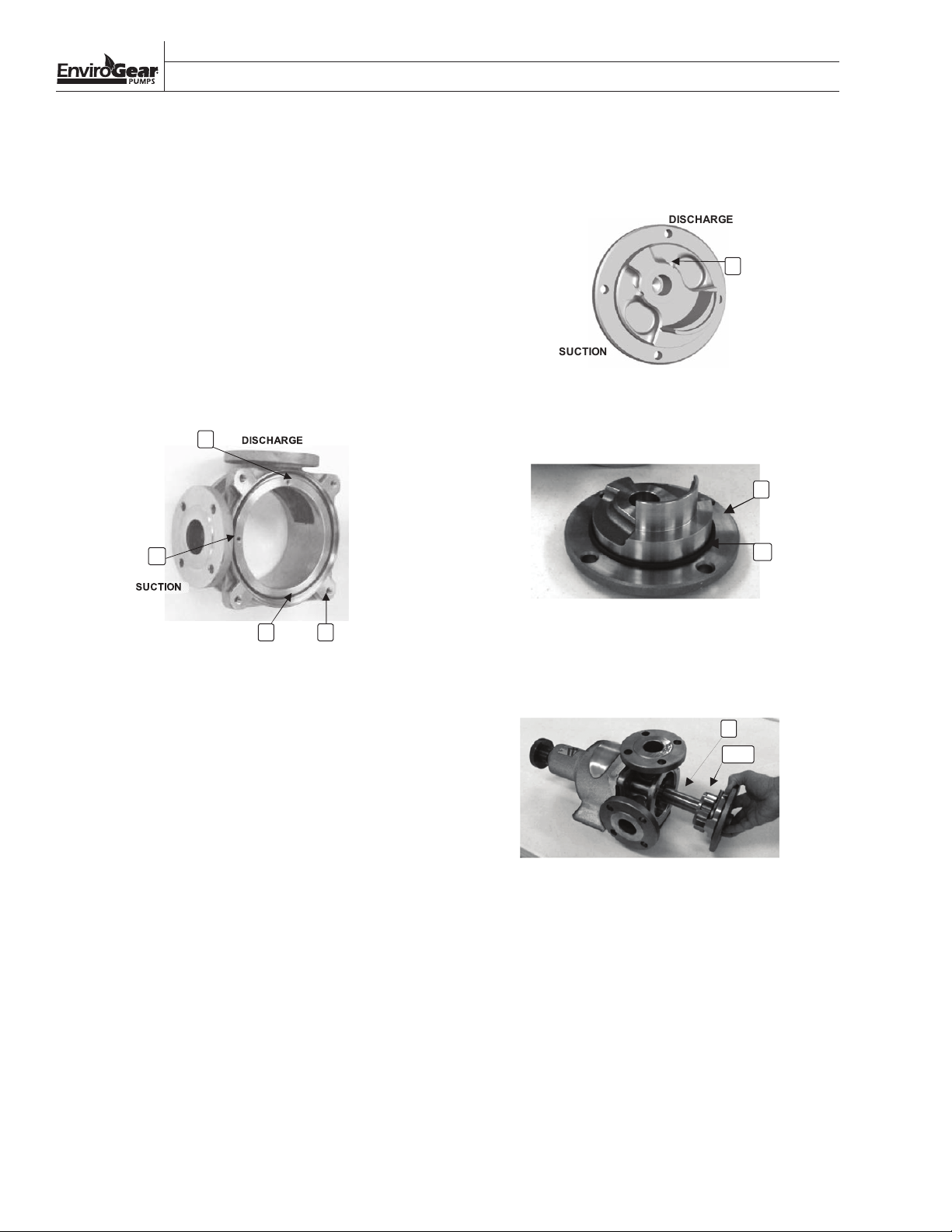
SECTION X
SUCTION
DISCHARGE
PUMP DISASSEMBLY & REPAIR PROCESS
PUMPING CHAMBER ASSEMBLY
1. Make sure the casing orifice plug and casing
block-off plug are in the correct locations:
• Install the casing orifice plug behind the
DISCHARGE port, if required.
• Install the casing block-off plug behind the
SUCTION port.
2. Position the canister O-ring in its groove in
the casing. If necessary, use a small amount
of light adhesive to keep the O-ring properly
positioned. For E1-133 and E1-222 models, it is
recommended to install the canister O-ring onto
the canister.
11
12
6. If the pump is not equipped with a relief valve,
ensure the head block-off plug is in the correct
location on the DISCHARGE side of the head.
14
Head Block-Off Plug
7. Slide the head O-ring onto the head. Take care to
avoid scratching the O-ring.
1
5
4 2
Casing Plugs and O-Rings
3. Slide the casing over the rotor, the lip of the
canister and magnet housing. It may take some
wiggling of the casing to get the canister and
magnet housing positioned within the casing’s
alignment counter-bore.
4. If necessary, rotate the casing to get the ports in
the preferred position.
5. Insert the screw that holds the outer drive
assembly to the casing.
a. First, torque 7 to 14 N•m (5 to 10 ft-lb) in an
alternating pattern
b. Next, torque 27 N•m (20 ft-lb) in an alternating
pattern
c.
Finally, torque final values in an alternating pattern:
i. 10 mm (3/8”) screws: 54 N•m (40 ft-lb)
ii. 13 mm (1/2”) screws: 88 N•m (65 ft-lb)
iii. 16 mm (5/8") screws: 61 N•m (45 ft-lb)
Head O-Ring
8. Position the head with the crescent facing
upward and set idler assembly and spindle in
place.
3
300
Head/Idler/Spindle Unit
9. Carefully insert the head/idler/spindle unit into
the rotor. Take care to avoid cracking or chipping
the carbon bushings.
10. Rotate the head so that the rotor and idler mesh
are between the ports.
11. Insert the screws that hold the head to the casing
and torque them to their final values:
a. 10 mm (3/8”) screws: 54 N•m (40 ft-lb)
b. 13 mm (1/2”) screws: 88 N•m (65 ft-lb)
c. 16 mm (5/8") screws: 61 N•m (45 ft-lb)
ENVIROGEAR 32 ENV-11000-E-04
Page 35
SECTION X
PUMP DISASSEMBLY & REPAIR PROCESS
RELIEF VALVE ASSEMBLY
(E1-2 thru E1-82 Models)
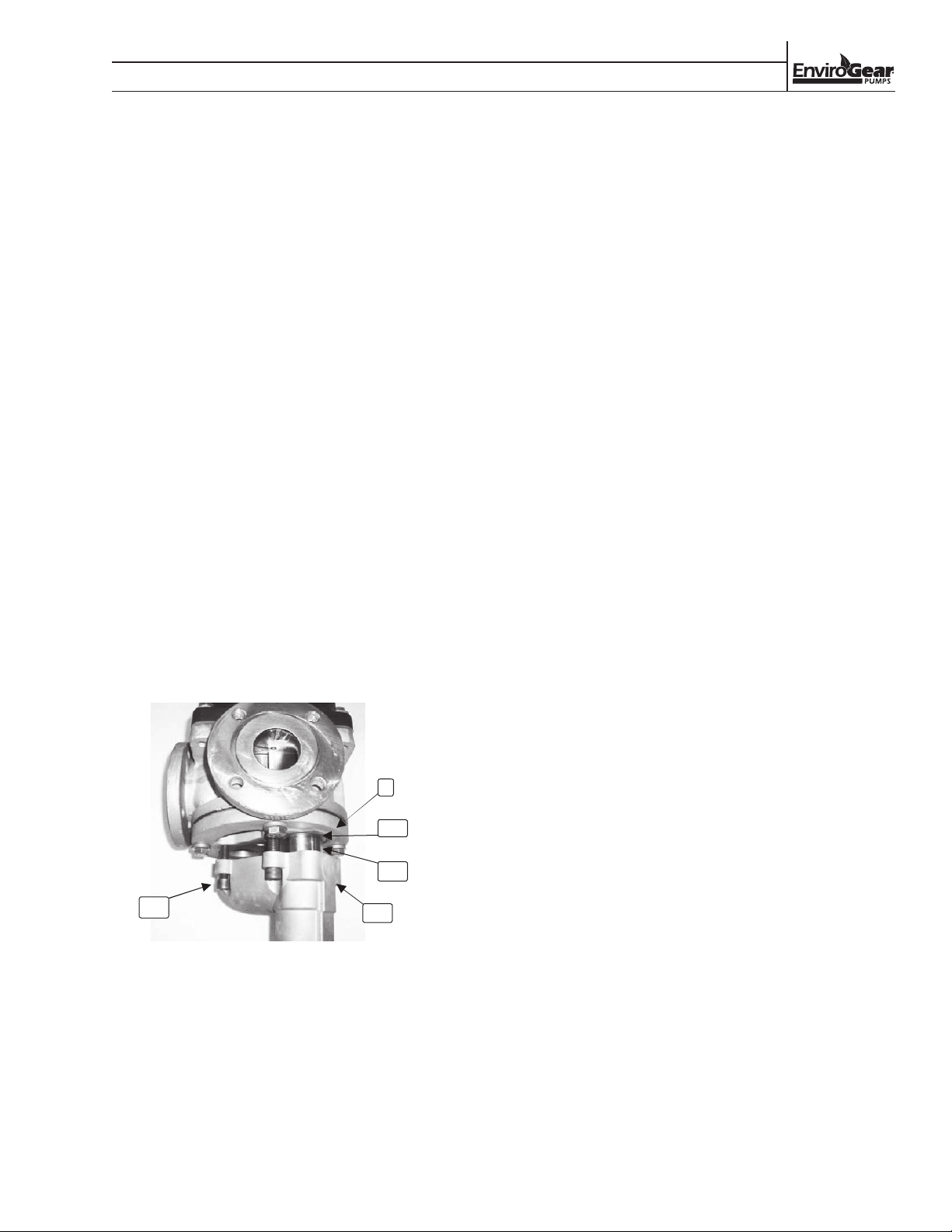
1. Check the valve body O-ring for damage or wear
and replace, if necessary.
2. Position the valve body O-ring in its groove in
the valve body. If necessary, use a small amount
of light adhesive to keep the O-ring properly
positioned.
3. Position the spring and poppet inside the valve
body.
4. Determine which pocket in the head is aligned
with the discharge port. The relief-valve poppet
must be positioned on the discharge pocket for
the valve to function correctly.
5. Position the valve body/spring/poppet onto the
pump head with the poppet over the discharge
pocket and loosely assemble the valve-body
screws.
6. Tighten the screws in an alternating pattern
until the valve body is fully contacting the head.
Torque the screw to their final values:
RELIEF VALVE ASSEMBLY
(E1-133 and E1-222 Models)
1. Clean all parts thoroughly.
2. Install the poppet.
3. Insert the required springs.
4. Insert the spring guide.
5. Install the bonnet with O-ring. Securely tighten
the bonnet.
6. Install adjusting screw and lock nut.
7. Tighten the adjustment screw to original setting.
8. Install the cap and O-ring. Securely tighten the
cap.
9. Attach the pressure relief valve to the head
using O-rings.
a. 10 mm (3/8”) screws: 54 N•m (40 ft-lb)
b. 13 mm (1/2”) screws: 88 N•m (65 ft-lb)
1
404
402
405
Relief Valve Assembly
401
ENV-11000-E-04 33 ENVIROGEAR
Page 36

SECTION X
NOTES
Page 37
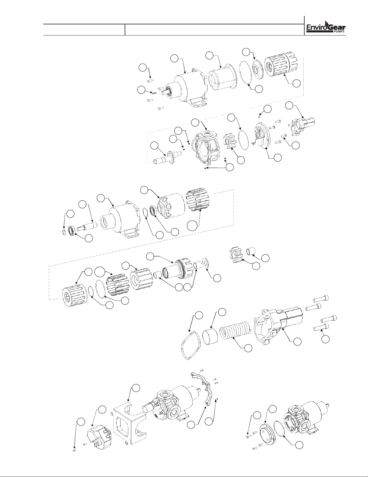
E1-2 THRU E1-82 MODELS
301
302
SECTION 8
EXPLODED VIEW & PARTS LISTING
108
103
105
101
10
8
102
7
100
6
200
4
14
400
5
2
11
12
3
300
9
1
13
**
104
105
106
505
204
204
203
203**
502
201
202
**
202
201
207
302
301
208 208
207
205
206
208208
404
402
401
405
403
501
601
603
504
503
602
ENV-11000-E-04 35 ENVIROGEAR
Page 38
SECTION 8
EXPLODED VIEW & PARTS LISTING
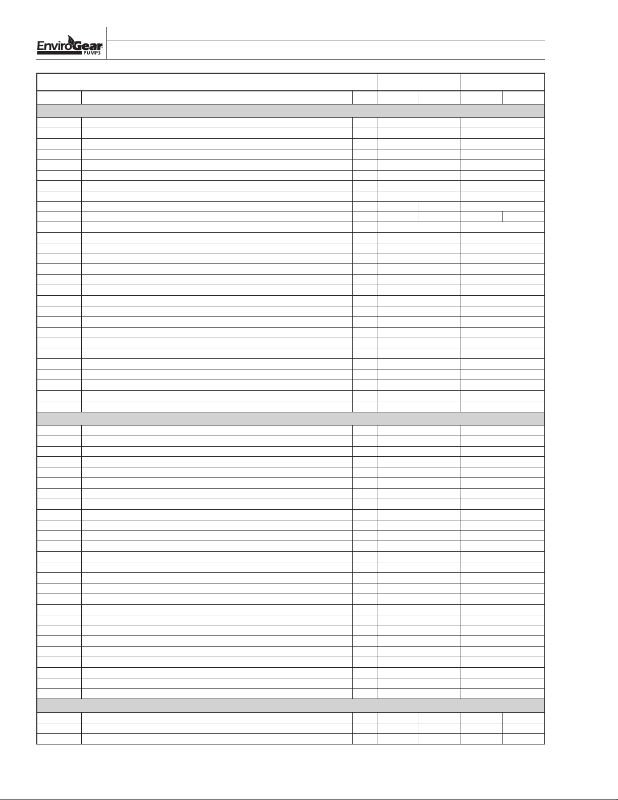
MODELS E1-2 & E1-4
CARBON STEEL STAINLESS STEEL
Item Description Qty. E1-2 E1-4 E1-2 E1-4
WET-END
1 Head for models with RV 1 HD37 HD39
1 Head for models without RV 1 HD5 HD6
1 Head for models with head jacket 1 HD9 HD10
2 Casing 1 1/2" ANSI 150# ports (90° orientation) 1 CS5 CS7
2 Casing DN40 PN16 ports (90° orientation) 1 CS5D CS7D
2 Casing 1 1/2" NPT tapped ports (90° orientation) 1 CS6 CS8
2 Casing 1 1/2" BSPT tapped ports (90° orientation) 1 CS6B CS8B
2 Casing 2" ANSI 150# ports (90° orientation) 1 CS46 CS47
3 Spindle hardened 1 PN5 PN7 NA
3 Spindle 1 PN1 PN3 PN2 PN4
4 O-ring, PFA enc. silicone, -161 size 1 HW123 HW123
4 O-ring, Kalrez 6375, -161 size 1 HW10 HW10
4 O-ring, FEP enc. Viton, -161 size 1 HW54 HW54
4 O-ring, Dupont Type A Viton, -161 size 1 HW6 HW6
5 O-ring, PFA enc. silicone, -241 size 1 HW122 HW122
5 O-ring, FEP enc. Viton, -241 size 1 HW53 HW53
5 O-ring, Dupont Type A Viton, -241 size 1 HW5 HW5
5 O-ring, Kalrez 6375, -241 size 1 HW9 HW9
6 Canister 1 CN1 CN1
7 Support Plate 1 PP2 PP2
9 Screw, 3/8-16 x 1.5'' long 4 HW101 HW101
9 Screw, 3/8-16 x 2'' long 4 HW107 HW107
10 Screw, 3/8-16 x 1.5'' long 4 HW101 HW101
11 Orifice Plug, <5000 cst 1 OF3 OF3
12 Solid Setscrew, 3/8", SS 1 HW112 HW112
13 Pipe Plug, 1/4" NPT, SS 1 HW14 HW14
14 Solid Setscrew, 3/8", SS 1 HW112 HW112
15 Washer, 3/8" 8 HW90 HW90
MAGNET HOUSING ASSEMBLY
101 Magnet Housing, with temp. probe port 1 MH11 MH11
101 Magnet Housing, 143/5TC close coupled 1 MH38 MH38
101 Magnet Housing, 182/4TC and 213/5TC close coupled 1 MH39 MH39
102/103/104 Outer Ring Assembly for M7L and M7M magnets (OR14, MS1, and SH1) 1 OR14-7L-S OR14-7L-S
102/103/104 Outer Ring Assembly for M7L and M7M magnets (OR14, MS1, and Hollow Shaft) 1 OR14-7L-14 OR14-7L-14
102/103/104 Outer Ring Assembly for M7L and M7M magnets (OR14, MS1, and Hollow Shaft) 1 OR14-7L-18 OR14-7L-18
102/103/104 Outer Ring Assembly for M6L and M6M magnets (OR2, MS1, and SH1) 1 OR2-6L-S OR2-6L-S
102/103/104 Outer Ring Assembly for M6L and M6M magnets (OR2, MS1, and Hollow Shaft) 1 OR2-6L-14 OR2-6L-14
102/103/104 Outer Ring Assembly for M6L and M6M magnets (OR2, MS1, and Hollow Shaft) 1 OR2-6L-18 OR2-6L-18
102/103/104 Outer Ring Assembly for M6H magnets (OR2, MS4, and SH1) 1 OR2-6H-S OR2-6H-S
102/103/104 Outer Ring Assembly for M6H magnets (OR2, MS4, and Hollow Shaft) 1 OR2-6H-14 OR2-6H-14
102/103/104 Outer Ring Assembly for M6H magnets (OR2, MS4, and Hollow Shaft) 1 OR2-6H-18 OR2-6H-18
102/103/104 Outer Ring Assembly for M6L and M6M magnets (OR2, MS1, and Hollow Shaft) 1 OR2-6L-21 OR2-6L-21
102/103/104 Outer Ring Assembly for M6H magnets (OR2, MS4, and Hollow Shaft) 1 OR2-6H-21 OR2-6H-21
103 Shaft, 3/4" dia 1 SH1 SH1
8 Drive Key, 3/16'' x 3/16'' x 1'' 1 HW4 HW4
104 Magnet Segment, SC ** MS4 MS4
104 Magnet Segment, NIB ** MS1 MS1
105 Ball Bearing, high temp clearance (std) 2 HW222 HW222
106 Spacer, for close-coupled shaft 1 HW195 HW195
106 Wave Spring 1 HW16 HW16
108 Snap Ring, for 140TC/180TC close-coupled shaft 1 HW196 HW196
108 Snap Ring, for 210TC/250TC close-coupled shaft 1 HW197 HW197
108 Snap Ring, for std shaft 1 HW2 HW2
110 Magnet Housing to C-Face Adapter (143/5TC) 1 MH36 MH36
110 Magnet Housing to C-Face Adapter (143/5TC and 182/4TC) 1 MH37 MH37
ROTATING ASSEMBLIES
201 Rotor A/B
201 Rotor high visc clearance, C/F
201 Rotor high temp clearance, D/E 1 RT45 RT49 RT47 RT50
** Magnet quantities may vary depending on pump configuration
1
RT1 RT3 RT2 RT4
RT46 RT24 RT48 RT51
1
ENVIROGEAR 36 ENV-11000-E-04
Page 39
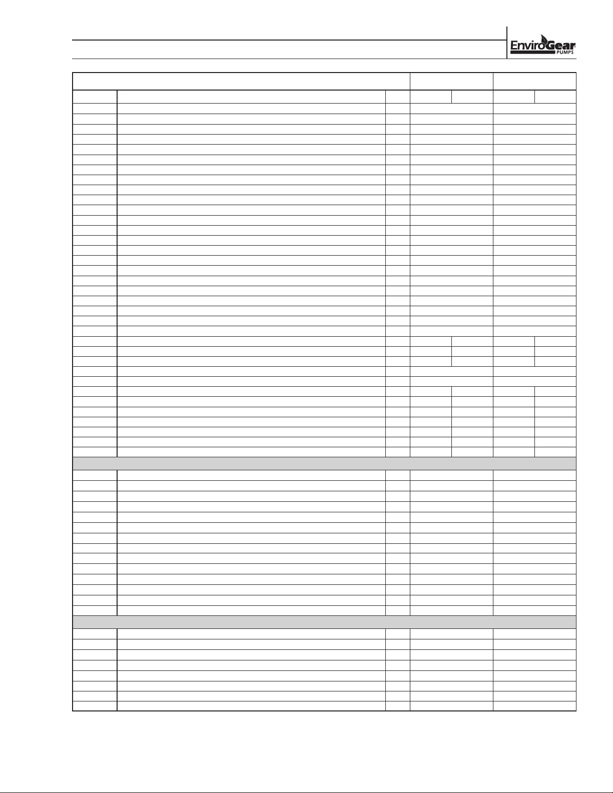
SECTION 6
EXPLODED VIEW & PARTS LISTING, CONT.
MODELS E1-2 & E1-4
CARBON STEEL STAINLESS STEEL
Item Description Qty. E1-2 E1-4 E1-2 E1-4
202 Inner Ring 1 IR1 IR1
203 Magnet Segment, NIB ** MS1 MS1
203 Magnet Segment, SC ** MS4 MS4
204 Sleeve 1 SL1 SL1
205 O-ring, PFA enc. silicone, -042 size 1 HW116 HW116
205 O-ring, FEP enc. Viton, -042 size 1 HW47 HW47
205 O-ring, Kalrez 6375, -042 size 1 HW12 HW12
205 O-ring, Dupont Type A Viton, -042 size 1 HW8 HW8
206 O-ring, PFA enc. silicone, -155 size 1 HW124 HW124
206 O-ring, FEP enc. Viton, -155 size 1 HW55 HW55
206 O-ring, Dupont Type A Viton, -155 size 1 HW7 HW7
206 O-ring, Kalrez 6375, -155 size 1 HW11 HW11
207 Thrust Bushing, TC 1 BU44 N/A
207 Thrust Bushings bronze 1 BU63 BU63
207 Thrust Bushing, CG 1 BU24 BU24
207 Thrust Bushing, ROC Carbon 1 BU118 BU118
208 Radial bushing, TC 2 BU42 N/A
208 Radial Bushing, bronze 2 BU56 BU56
208 Radial Bushing, bronze, high visc clearance 2 BU68 BU68
208 Radial bushing, CG 2 BU45 BU45
208 Radial Bushing, CG, high visc clearance 2 BU33 BU33
208 Radial Bushing, ROC Carbon 2 BU117 BU117
208 Radial Bushing, ROC Carbon, high visc clearance 2 BU116 BU116
301 Idler A/B 1 ID1 ID3 ID2 ID4
301 Idler high visc clearance, C/F 1 ID40 ID18 ID42 ID45
301 Idler high temp clearance, D/E 1 ID39 ID43 ID41 ID44
302 Radial Bushing, ROC Carbon 1 BU120 BU120
302 Radial Bushing, ROC Carbon, high visc clearance 1 BU121 BU121
302 Radial bushing, TC 1 BU41 BU42 N/A N/A
302 Radial bushing, bronze 1 BU55 BU57 BU55 BU57
302 Radial bushing, bronze, high visc clearance 4 BU70 BU71 BU70 BU71
302 Radial bushing, CG 1 BU1 BU45 BU1 BU45
302 Radial bushing, CG, high visc clearance 1 BU32 BU33 BU32 BU33
302 Radial Bushing, ROC Carbon 1 BU114 BU117 BU114 BU117
302 Radial Bushing, ROC Carbon, high visc clearance 1 BU115 BU116 BU115 BU116
RELIEF VALVE ASSEMBLY
401 Valve Body 1 VB12 VB11
402 Valve Poppet, 50 psi 1 VP24 VP5
402 Valve Poppet, 75 psi 1 VP25 VP13
402 Valve Poppet, 100 psi 1 VP26 VP6
402 Valve Poppet, 125 psi 1 VP27 VP15
402 Valve Poppet, 150 psi 1 VP28 VP7
402 Valve Poppet, 175 psi 1 VP29 N/A
402 Valve Poppet, 200 psi 1 VP30 N/A
403 Valve Spring, low pressure 1 VS2 VS2
403 Valve Spring, high pressure 1 VS4 VS4
404 O-ring, PFA enc. silicone, -241 size 1 HW122 HW122
404 O-ring, FEP enc. Viton, -241 size 1 HW53 HW53
404 O-ring, Dupont Type A Viton, -241 size 1 HW5 HW5
404 O-ring, Kalrez 6375, -241 size 1 HW9 HW9
OPTIONS
501 Full Jacket 1 JK8 JK8
506 Heat Transfer Cement (gallon can) 1 AD4 AD4
601 Head Jacket 1 HJ1 HJ1
602 O-ring, PFA enc. silicone, -241 size 1 HW122 HW122
603 Screw, 3/8-16 x 2'' long 4 HW107 HW107
605 1/4" NPT Thermocouple RTD Unit, NEMA 4 1 HW219 HW219
605 1/4" NPT Thermocouple RTD Unit, NEMA 4X SS ATEX 1 HW275 HW275
801 Rotor Puller Tool, E1-2, E1-4
** Magnet quantities may vary depending on pump configuration
1
F-00097
F-00097
ENV-11000-E-04 37 ENVIROGEAR
Page 40
SECTION 8
EXPLODED VIEW & PARTS LISTING
MODELS E1-24 & E1-32
DUCTILE IRON CARBON STEEL STAINLESS STEEL
Item Description Qty. E1-24 E1-32 E1-24 E1-32 E1-24 E1-32
WET-END
1 Head for models with RV 1
1 Head for models with head jacket 1 HD54 HD43 HD44
1 Head for models without RV 1 HD51 HD13 HD14
2 Casing 2" NPT ports (90° orientation) 1 CS64 CS23 CS24
2 Casing 2" BSPT ports (90° orientation) 1 CS64B CS23B CS24B
2 Casing 2" ANSI 150# ports (90° orientation) 1 CS65 CS21 CS22
2 Casing DN50 PN16 ports (90° orientation) 1 NA CS21D CS22D
2 Casing 2" ANSI 150# ports (180° orientation) 1 CS103 CS115 CS99
2 Casing 3" ANSI 150# ports (90° orientation) 1 NA CS50 CS51
3 Spindle hardened 1 PN24 PN27 PN24 PN27 NA NA
3 Spindle 1 PN13 PN9 PN13 PN9 PN14 .
4 O-ring, PFA enc. silicone, -264 size 1 HW119 HW119 HW119
4 O-ring, FEP enc. Viton, -264 size 1 HW50 HW50 HW50
4 O-ring, Dupont Type A Viton, -264 size 1 HW25 HW25 HW25
4 O-ring, Kalrez 6375, -264 size 1 HW135 HW135 HW135
5 O-ring, PFA enc. silicone, -259 size 1 HW118 HW118 HW118
5 O-ring, FEP enc. Viton, -259 size 1 HW49 HW49 HW49
5 O-ring, Dupont Type A Viton, -259 size 1 HW228 HW228 HW228
5 O-ring, Kalrez 6375, -2579size 1 HW229 HW229 HW229
6 Canister 1 CN3 CN3 CN3
7 Support Plate 1 PP4 PP4 PP4
9 Screw, 1/2-13 x 1.75'' long 4 HW96 HW96 HW96
10 Screw, 1/2-13 x 1.75'' long 4 HW96 HW96 HW96
11 Orifice Plug, <5000 cst 1 OF2 OF2 OF2
12 Solid Setscrew, 3/8", SS 1 HW112 HW112 HW112
13 Pipe Plug, 1/4" NPT, SS 2 HW14 HW14 HW14
14 Solid Setscrew, 3/8", SS 1 HW112 HW112 HW112
15 Washer, 1/2" 8 HW89 HW89 HW89
HD52 HD20 HD21
MAGNET HOUSING ASSEMBLY
101 Magnet Housing, with temp. probe port 1 MH10 MH10 MH10
102/103/104 Outer Ring Assembly for M6L and M6M magnets (OR7, MS9 and SH2) 1 OR7-6L-S OR7-6L-S OR7-6L-S
102/103/104 Outer Ring Assembly for M6H magnets (OR7, MS7 and SH2) 1 OR7-6H-S OR7-6H-S OR7-6H-S
102/103/104 Outer Ring Assembly for M7L and M7M magnets (OR13, MS9 and SH2) 1 OR13-7L-S OR13-7L-S OR13-7L-S
103 Shaft, 1-1/8" dia 1 SH2 SH2 SH2
8 Drive Key, 1/4'' x 1/4'' x 1.5'' 1 HW18 HW18 HW18
104 Magnet Segment, SC ** MS7 MS7 MS7
104 Magnet Segment, NIB ** MS9 MS9 MS9
105 Ball Bearing, high temp clearance (std) 2 HW223 HW223 HW223
106 Wave Spring 1 HW24 HW24 HW24
108 Snap Ring 1 HW19 HW19 HW19
ROTATING ASSEMBLIES
201 Rotor A/B
201 Rotor high visc clearance, C/F
201 Rotor high temp clearance, D/E 1 RT26 RT30 RT26 RT30 RT28 RT32
202 Inner Ring 1 IR4 IR4 IR4
203 Magnet Segment, NIB ** MS9 MS9 MS9
203 Magnet Segment, SC ** MS7 MS7 MS7
204 Sleeve 1 SL3 SL3 SL3
205 O-ring, PFA enc. silicone, -042 size 1 HW116 HW116 HW116
205 O-ring, FEP enc. Viton, -042 size 1 HW47 HW47 HW47
205 O-ring, Kalrez 6375, -042 size 1 HW12 HW12 HW12
205 O-ring, Dupont Type A Viton, -042 size 1 HW8 HW8 HW8
206 O-ring, PFA enc. silicone, -258 size 1 HW121 HW121 HW121
206 O-ring, FEP enc. Viton, -258 size 1 HW52 HW52 HW52
** Magnet quantities may vary depending on pump configuration
1
RT13 RT5 RT13 RT5 RT14 RT6
RT27 RT31 RT27 RT31 RT29 RT33
1
ENVIROGEAR 38 ENV-1100 0-E-04
Page 41
SECTION 6
EXPLODED VIEW & PARTS LISTING, CONT.
MODELS E1-24 & E1-32
DUCTILE IRON CARBON STEEL STAINLESS STEEL
Item Description Qty. E1-24 E1-32 E1-24 E1-32 E1-24 E1-32
206 O-ring, Dupont Type A Viton, -257 size 1 HW26 HW26 HW26
206 O-ring, Kalrez 6375, -257 size 1 HW44 HW44 HW44
207 Thrust Bushing, TC 1 BU31 BU31 N/A
207 Thrust Bushings bronze 1 BU64 BU64 BU64
207 Thrust Bushing, CG 1 BU23 BU23 BU23
207 Thrust Bushing, ROC Carbon 1 BU123 BU123 BU123
208 Radial Bushing, TC 2 BU40 BU40 N/A
208 Radial bushing, bronze 2 BU59 BU59 BU59
208 Radial Bushing, bronze, high visc clearance 2 BU69 BU69 BU69
208 Radial Bushing, CG 2 BU15 BU15 BU15
208 Radial Bushing, CG, high visc clearance 2 BU35 BU35 BU35
208 Radial Bushing, ROC Carbon 2 BU119 BU119 BU119
208 Radial Bushing, ROC Carbon, high visc clearance 2 BU122 BU122 BU122
301 Idler A/B 1 ID13 ID7 ID13 ID7 ID14 ID8
301 Idler high visc clearance, C/F 1 ID21 ID25 ID21 ID25 ID23 ID25
301 Idler high temp clearance, D/E 1 ID20 ID24 ID20 ID24 ID22 ID24
302 Radial bushing, TC 1 BU39 BU40 BU39 BU40 N/A N/A
302 Radial bushing, bronze 1 BU58 BU59 BU58 BU59 BU58 BU59
302 Radial bushing, bronze, high visc clearance 1 BU72 BU69 BU72 BU69 BU72 BU69
302 Radial bushing, CG 1 BU19 BU15 BU19 BU15 BU19 BU15
302 Radial bushing, CG, high visc clearance 1 BU34 BU35 BU34 BU35 BU34 BU35
302 Radial Bushing, ROC Carbon 1 BU120 BU119 BU120 BU119 BU120 BU119
302 Radial Bushing, ROC Carbon, high visc clearance 1 BU121 BU122 BU121 BU122 BU121 BU122
RELIEF VALVE ASSEMBLY
401 Valve Body 1 VB7 VB7 VB8
402 Valve Poppet, 50 psi 1 VP18 VP18 VP4
402 Valve Poppet, 75 psi 1 VP17 VP17 VP14
402 Valve Poppet, 100 psi 1 VP19 VP19 VP1
402 Valve Poppet, 125 psi 1 VP20 VP20 VP9
402 Valve Poppet, 150 psi 1 V P21 VP21 VP2
402 Valve Poppet, 175 psi 1 VP22 VP22 N/A
402 Valve Poppet, 200 psi 1 VP23 VP23 N/A
403 Valve Spring, low pressure 1 VS1 VS1 VS1
403 Valve Spring, high pressure 1 VS5 VS5 VS5
404 O-ring, PFA enc. silicone, -250 size 1 HW120 HW120 HW120
404 O-ring, FEP enc. Viton, -250 size 1 HW51 HW51 HW51
404 O-ring, Dupont Type A Viton, -250 size 1 HW37 HW37 HW37
404 O-ring, Kalrez 6375, -250 size 1 HW159 HW159 HW159
405 Screw Body, 1/2-13 x 2'' long 4 HW33 HW33 HW33
OPTIONS
501 Full Jacket
506 Heat Transfer Cement (gallon can) 1 AD4 AD4 AD4
601 Head Jacket 1 HJ2 HJ2 HJ2
602 O-ring, PFA enc. silicone, -259 size 1 HW118 HW118 HW118
603 Screw, 1/2-13 x 1.75'' long 4 HW96 HW96 HW96
605 1/4" NPT Thermocouple RTD Unit, NEMA 4 1 HW219 HW219 HW219
605 1/4" NPT Thermocouple RTD Unit, NEMA 4X SS ATEX 1 HW275 HW275 HW275
801 Rotor Puller Tool Kit, E1-24 thru E1-82
** Magnet quantities may vary depending on pump configuration
1
1
JK1 JK1 JK1
F-00096 F-00096
F-00096
ENV-11000-E-04 39 ENVIROGEAR
Page 42
SECTION 8
EXPLODED VIEW & PARTS LISTING
MODELS E1-55, E1-69, E1-82 DUCTILE IRON CARBON STEEL STAINLESS STEEL
Item Description Qty. E1-55 E1-69 E1-82 E1-55 E1-69 E1-82 E1-55 E1-69 E1-82
WET-END
1 Head for models with RV 1
1 Head for models with head jacket 1 HD55 HD45 HD46
1 Head for models without RV 1 HD53 HD17 HD18
2 Casing 3" ANSI 150# ports (90° orientation) 1 CS59 CS19 CS20
2 Casing 3" DN80 PN16 ports (90° orientation) 1 NA CS19D CS20D
2 Casing 3" ANSI 150# ports (180° orientation) 1 NA NA CS95
2 Casing 4" ANSI 150# ports (90° orientation) 1 CS63 CS40 CS37
3 Spindle hardened 1 PN28 PN26 PN29 PN28 PN26 PN29 NA NA NA
3 Spindle 1 PN15 PN17 PN11 PN15 PN17 PN11 PN16 PN18 PN12
4 O-ring, PFA enc. silicone, -275 size 1 HW115 HW115 HW115
4 O-ring, FEP enc. Viton, -275 size 1 HW46 HW46 HW46
4 O-ring, Dupont Type A Viton, -275 size 1 HW22 HW22 HW22
4 O-ring, Kalrez 6375, -275 size 1 HW75 HW75 HW75
5 O-ring, PFA enc. silicone, -267 size 1 HW114 HW114 HW114
5 O-ring, FEP enc. Viton, -267 size 1 HW45 HW45 HW45
5 O-ring, Dupont Type A Viton, -267 size 1 HW21 HW21 HW21
5 O-ring, Kalrez 6375, -267 size 1 HW74 HW74 HW74
6 Canister 1 CN2 CN2 CN2
7 Support Plate 1 PP3 PP3 PP3
9 Screw, 1/2-13 x 1.75'' long 4 HW96 HW96 HW96
10 Screw, 1/2-13 x 1.75'' long 4 HW96 HW96 HW96
11 Orifice Plug, <5000 cst 1 OF1 OF1 OF1
12 Solid Setscrew, 1/2", SS 1 HW113 HW113 HW113
13 Pipe Plug, 1/4" NPT, SS 2 HW14 HW14 HW14
14 Solid Setscrew, 3/8", SS 1 HW112 HW112 HW112
15 Washer, 1/2" 8
MAGNET HOUSING ASSEMBLY
101 Magnet Housing, with temp. probe port 1 MH12 MH12 MH12
102/103/104 Outer Ring Assembly for M7L and M7M magnets (OR12, MS6 and SH3) 1 OR12-7L-S OR12-7L-S OR12-7L-S
102/103/104 Outer Ring Assembly for M7L and M7M magnets (OR12, MS6 and SH2) 1 OR12-7L-V OR12-7L-V OR12-7L-V
102/103/104 Outer Ring Assembly for M6L and M6M magnets (OR10, MS6 and SH3) 1 OR10-6L-S OR10-6L-S OR10-6L-S
102/103/104 Outer Ring Assembly for M6L and M6M magnets (OR10, MS6 and SH2) 1 OR10-6L-V OR10-6L-V OR10-6L-V
102/103/104 Outer Ring Assembly for M6H magnets (OR10, MS8 and SH3) 1 OR10-6H-S OR10-6H-S OR10-6H-S
102/103/104 Outer Ring Assembly for M6H magnets (OR10, MS8 and SH2) 1 OR10-6H-V OR10-6H-V OR10-6H-V
103 Shaft, 1-7/16" dia 1 SH3 SH3 SH3
103 Shaft, 1-1/8" dia 1 SH2 SH2 SH2
8 Drive Key, 3/8'' x 3/8'' x 2.75'' (1-7/16" shaft) 1 HW34 HW34 HW34
8 Drive Key, 1/4'' x 1/4'' x 1.5'' (1-1/8" shaft) 1 HW18 HW18 HW18
104 Magnet Segment, SC ** MS8 MS8 MS8
104 Magnet Segment, NIB ** MS6 MS6 MS6
105 Ball Bearing, high temp clearance (std) 2 HW223 HW223 HW223
106 Wave Spring 1 HW24 HW24 HW24
108 Snap Ring 1 HW19 HW19 HW19
ROTATING ASSEMBLIES
201 Rotor A/B
201 Rotor high visc clearance, C/F
201 Rotor high temp clearance, D/E 1 RT34 RT38 RT42 RT34 RT38 RT42 RT36 RT40 RT43
202 Inner Ring 1 IR6 IR6 IR6
203 Magnet Segment, NIB ** MS6 MS6 MS6
203 Magnet Segment, SC ** MS8 MS8 MS8
204 Sleeve 1 SL2 SL2 SL2
205 O-ring, PFA enc. silicone, -042 size 1 HW116 HW116 HW116
205 O-ring, FEP enc. Viton, -042 size 1 HW47 HW47 HW47
** Magnet quantities may vary depending on pump configuration
1
1
HD49 HD19 HD22
HW89 HW89 HW89
RT15 RT17 RT19 RT15 RT17 RT19 RT16 RT18 RT20
RT35 RT39 RT25 RT35 RT39 RT25 RT37 RT41 RT44
ENVIROGEAR 40 ENV-11000-E-04
Page 43
SECTION 6
EXPLODED VIEW & PARTS LISTING, CONT.
MODELS E1-55, E1-69, E1-82 DUCTILE IRON CARBON STEEL STAINLESS STEEL
Item Description Qty. E1-55 E1-69 E1-82 E1-55 E1-69 E1-82 E1-55 E1-69 E1-82
205 O-ring, Kalrez 6375, -042 size 1 HW12 HW12 HW12
205 O-ring, Dupont Type A Viton, -042 size 1 HW8 HW8 HW8
206 O-ring, PFA enc. silicone, -267 size 1 HW114 HW114 HW114
206 O-ring, FEP enc. Viton, -267 size 1 HW45 HW45 HW45
206 O-ring, Dupont Type A Viton, -267 size 1 HW21 HW21 HW21
206 O-ring, Kalrez 6375, -267 size 1 HW74 HW74 HW74
207 Thrust Bushing, TC 1 BU28 BU28 N/A
207 Thrust Bushings bronze 1 BU65 BU65 BU65
207 Thrust Bushing, CG 1 BU29 BU29 BU29
207 Thrust Bushing, ROC Carbon 1 BU130 BU130 BU130
208 Radial Bushing, TC 2 BU25 BU25 N/A
208 Radial Bushing, bronze 2 BU60 BU60 BU60
208 Radial bushing, bronze, high visc clearance 2 BU67 BU67 BU67
208 Radial Bushing, CG 2 BU9 BU9 BU9
208 Radial Bushing, CG, high visc clearance 2 BU30 BU30 BU30
208 Radial Bushing, ROC Carbon 2 BU124 BU124 BU124
208 Radial Bushing, ROC Carbon, high visc clearance 2 BU127 BU127 BU127
301 Idler A/B 1 ID11 ID9 ID5 ID11 ID9 ID5 ID12 ID9 ID5
301 Idler high visc clearance, C/F 1 ID29 ID33 ID19 ID29 ID33 ID19 ID31 ID33 ID19
301 Idler high temp clearance, D/E 1 ID28 ID32 ID36 ID28 ID32 ID36 ID30 ID32 ID36
302 Radial bushing, TC 1 BU26 BU27 BU25 BU26 BU27 BU25 N/A N/A N/A
302 Radial bushing, bronze 1 BU62 BU61 BU60 BU62 BU61 BU60 BU62 BU61 BU60
302 Radial bushing, bronze, high visc clearance 1 BU66 BU73 BU67 BU66 BU73 BU67 BU66 BU73 BU67
302 Radial bushing, CG 1 BU17 BU11 BU9 BU17 BU11 BU9 BU17 BU11 BU9
302 Radial bushing, CG, high visc clearance 1 BU36 BU37 BU30 BU36 BU37 BU30 BU36 BU37 BU30
302 Radial Bushing, ROC Carbon 1 BU126 BU125 BU124 BU126 BU125 BU124 BU126 BU125 BU124
302 Radial Bushing, ROC Carbon, high visc clearance 1 BU129 BU128 BU127 BU129 BU128 BU127 BU129 BU128 BU127
RELIEF VALVE ASSEMBLY
401 Valve Body 1 VB5 VB5 VB6
402 Valve Poppet, 50 psi 1 VP18 VP18 VP4
402 Valve Poppet, 75 psi 1 VP17 VP17 VP14
402 Valve Poppet, 100 psi 1 VP19 VP19 VP1
402 Valve Poppet, 125 psi 1 VP20 VP20 VP9
402 Valve Poppet, 150 psi 1 VP21 VP21 VP2
402 Valve Poppet, 175 psi 1 VP22 VP22 N/A
402 Valve Poppet, 200 psi 1 VP23 VP23 N/A
403 Valve Spring, low pressure 1 VS1 VS1 VS1
403 Valve Spring, high pressure 1 VS5 VS5 VS5
404 O-ring, PFA enc. silicone, -261 size 1 HW117 HW117 HW117
404 O-ring, FEP enc. Viton, -261 size 1 HW48 HW48 HW48
404 O-ring, Dupont Type A Viton, -261 size 1 HW36 HW36 HW36
404 O-ring, Kalrez 6375, -261 size 1 HW73 HW73 HW73
405 Screw Body, 1/2-13 x 2'' long 4 HW33 HW33 HW33
OPTIONS
501 Full Jacket
506 Heat Transfer Cement (gallon can) 1 AD4 AD4 AD4
601 Head Jacket 1 HJ3 HJ3 HJ3
602 O-ring, PFA enc. silicone, -267 size 1 HW114 HW114 HW114
603 Screw, 1/2-13 x 1.75'' long 4 HW96 HW96 HW96
605 1/4" NPT Thermocouple RTD Unit, NEMA 4 1 HW219 HW219 HW219
605 1/4" NPT Thermocouple RTD Unit, NEMA 4X SS ATEX 1 HW275 HW275 HW275
801 Rotor Puller Tool Kit, E1-24 thru E1-82
** Magnet quantities may vary depending on pump configuration
1
1
JK3 JK3 JK3
F-00096 F-00096
F-00096
ENV-11000-E-04 41 ENVIROGEAR
Page 44

SECTION X
NOTES
Page 45
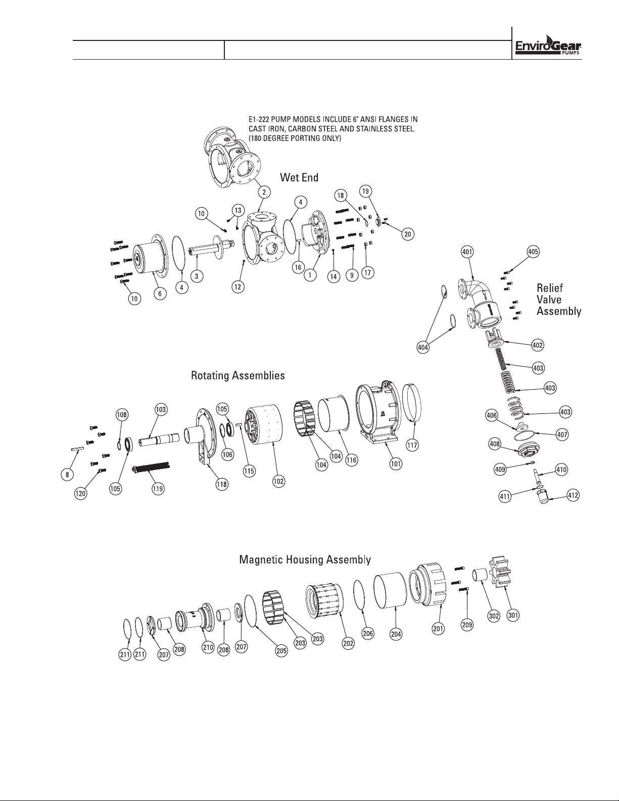
E1-133 AND E1-222 MODELS
SECTION 8
EXPLODED VIEW & PARTS LISTING
LE0117, REV. C
ENV-11000-E-04 43 ENVIROGEAR
Page 46
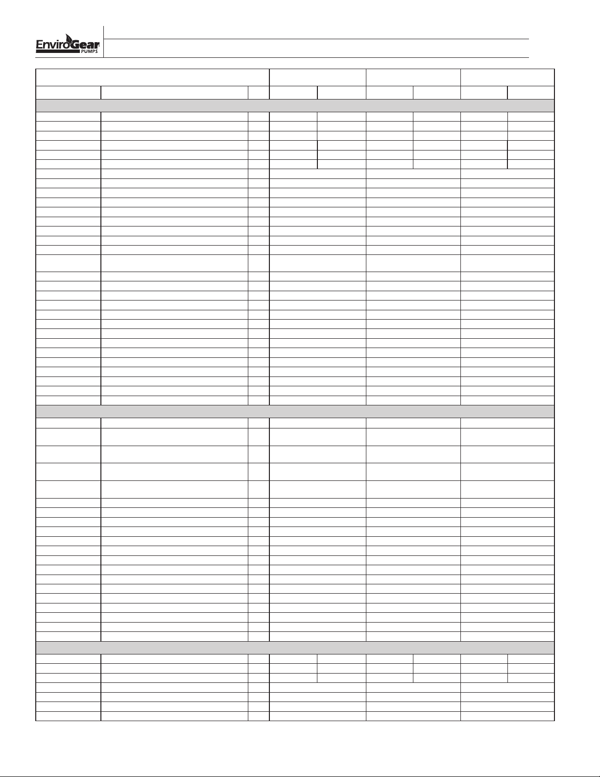
SECTION 8
EXPLODED VIEW & PARTS LISTING
MODELS E1-133 & E1-222 CAST IRON CARBON STEEL STAINLESS STEEL
Item Description Qty.
1 Head for models with RV 1 HD77 HD78 HD75 HD76 HD74
1 Head for models without RV 1 HD77 HD78 HD75 HD76 HD74
2 Casing 4" ANSI 150# ports (90° orientation) 1 CS123 NA CS124 NA CS118
2 Casing 6" ANSI 150# ports (180° orientation) 1 NA CS122 NA CS121 NA
3 Spindle hardened 1 PN80 PN82 PN80 PN82 PN81
3 Spindle 1 PN78 PN76 PN78 PN76 PN74
4 O-Ring, Viton, -276 Size 1 HW244 HW244 HW244
4 O-Ring, FEP-Encapsulated Viton, -276 Size 1 HW245 HW245 HW245
4 O-Ring, Kalrez, -276 Size 1 HW246 HW246 HW246
4 O-Ring, PFA-Encapsulated Silicon, -276 Size 1 HW247 HW247 HW247
5 O-Ring, Viton, -276 Size 1 HW244 HW244 HW244
5 O-Ring, FEP-Encapsulated Viton, -276 Size 1 HW245 HW245 HW245
5 O-Ring, Kalrez, -276 Size 1 HW246 HW246 HW246
5 O-Ring, PFA-Encapsulated Silicon, -276 Size 1 HW247 HW247 HW247
6 Canister w/Integral Support Plate 1 CN4 CN4 CN4
7
9 Stud, 5/8"-11 x 2.50" long 8 T09C625B50WA2A2 T09C625B50WA2A2 T09C625B50WA2A2
10 Screw, 5/8"-11 x 2.25'' long 8 HW103 HW103 HW103
11 Orifice Plug, <5000 cst 1 OF1 OF1 OF1
12 Solid Setscrew, 1/2"-13 x .50" long, SS 1 HW113 HW113 HW113
13 Pipe Plug, 3/8" NPT 2 PLUG-038NSH-230 PLUG-038NSH-230 PLUG-038NSH-230
14 Pipe Plug, 1/4" NPT 1 PLUG-025NSH-230 PLUG-025NSH-230 PLUG-025NSH-230
16 Dowel Pin, 5/8" x 1.25" long, SS 1 HW252 HW252 HW252
17 Nut, 5/8"-11 8 N04C625562WA2A2 N04C625562WA2A2 N04C625562WA2A2
18 O-Ring, Viton, -132 Size 1 HW248 HW248 HW248
18 O-Ring, Kalrez, -132 Size 1 HW249 HW249 HW249
18 O-Ring, PFA-Encapsulated Silicon, -132 Size 1 HW250 HW250 HW250
18 O-Ring, FEP-Encapsulated Viton, -132 Size 1 HW251 HW251 HW251
19 Head Plug 1 HP1 HP1 HP1
20 Screw, 3/8"-16 x .75" long 2
Separate Support Plate not required on E1-133
& E1-222
N/A N/A N/A N/A
MAGNET HOUSING ASSEMBLY
101 Magnet Housing 1 MH40 MH40 MH40
102/103/104/115/116
102/103/104/115/116
102/103/104/115/116
102/103/104/115/116
103 Shaft, 1-15/16" dia 1 SH23 SH23 SH23
8 Drive Key, 1/2'' x 1/2'' x 1.875'' 1 HW274 HW274 HW274
104 Magnet Segment, North, SC ** MS14 MS14 MS14
104 Magnet Segment, South, SC ** MS16 MS16 MS16
104 Magnet Segment, North, NIB ** MS10 MS10 MS10
104 Magnet Segment, South, NIB ** MS12 MS12 MS12
105 Ball Bearing, high temp clearance (std) 2 HW235 HW235 HW235
106 Wave Spring 1 HW242 HW242 HW242
108 Snap Ring 1 HW241 HW241 HW241
115 Drive Key, 1/2'' x 1/2'' x 1.875'' 1 HW274 HW274 HW274
116 Outer Magnet Sleeve 1 SL10 SL10 SL10
117 Skid Ring 1 SR1 SR1 SR1
118 Bearing Housing 1 BH1 BH1 BH1
119 Screw, 5/8"-11 x 10'' long 3 HW240 HW240 HW240
120 Screw, 5/8"-11 x 1.50'' long 6 S01C625A50WA2A4 S01C625A50WA2A4 S01C625A50WA2A4
Outer Ring Assembly for M6L and M6M magnets (OR27,
MS10, MS12, SH23, HW274, and SL10)
Outer Ring Assembly for M6H magnets (OR27, MS14,
MS16, SH23, HW274, and SL10)
Outer Ring Assembly for M7L and M7M magnets (OR27,
MS10, MS12, SH23, HW274, and SL10)
Outer Ring Assembly for M7H magnets (OR27, MS14,
MS16, SH23, HW274, and SL10)
ROTATING ASSEMBLIES
201 Rotor A/B 1 RT89 RT87 RT89 RT87 RT85 RT83
201 Rotor high visc clearance, C/F 1 RT92 RT98 RT92 RT98 RT95 RT101
201 Rotor high temp clearance, D/E 1 RT93 RT99 RT93 RT99 RT96 RT102
202 Inner Ring 1 IR10 IR10 IR8
203 Magnet Segment, North, SC ** MS15 MS15 MS15
203 Magnet Segment, South, SC ** MS17 MS17 MS17
203 Magnet Segment, North, NIB ** MS11 MS11 MS11
** Magnet quantities may vary depending on pump configuration
E1-133 E1-222 E1-133 E1-222 E1-133 E1-222
WET-END
S01C375750WA2A2 S01C375750WA2A2 S01C375750WA2A2
1 OR27-6L-S OR27-6L-S OR27-6L-S
1 OR27-6H-S OR27-6H-S OR27-6H-S
1 OR27-7L-S OR27-7L-S OR27-7L-S
1 OR27-7H-S OR27-7H-S OR27-7H-S
HD72
HD72
NA
CS117
PN83
PN72
ENVIROGEAR 44 ENV-11000-E-04
Page 47
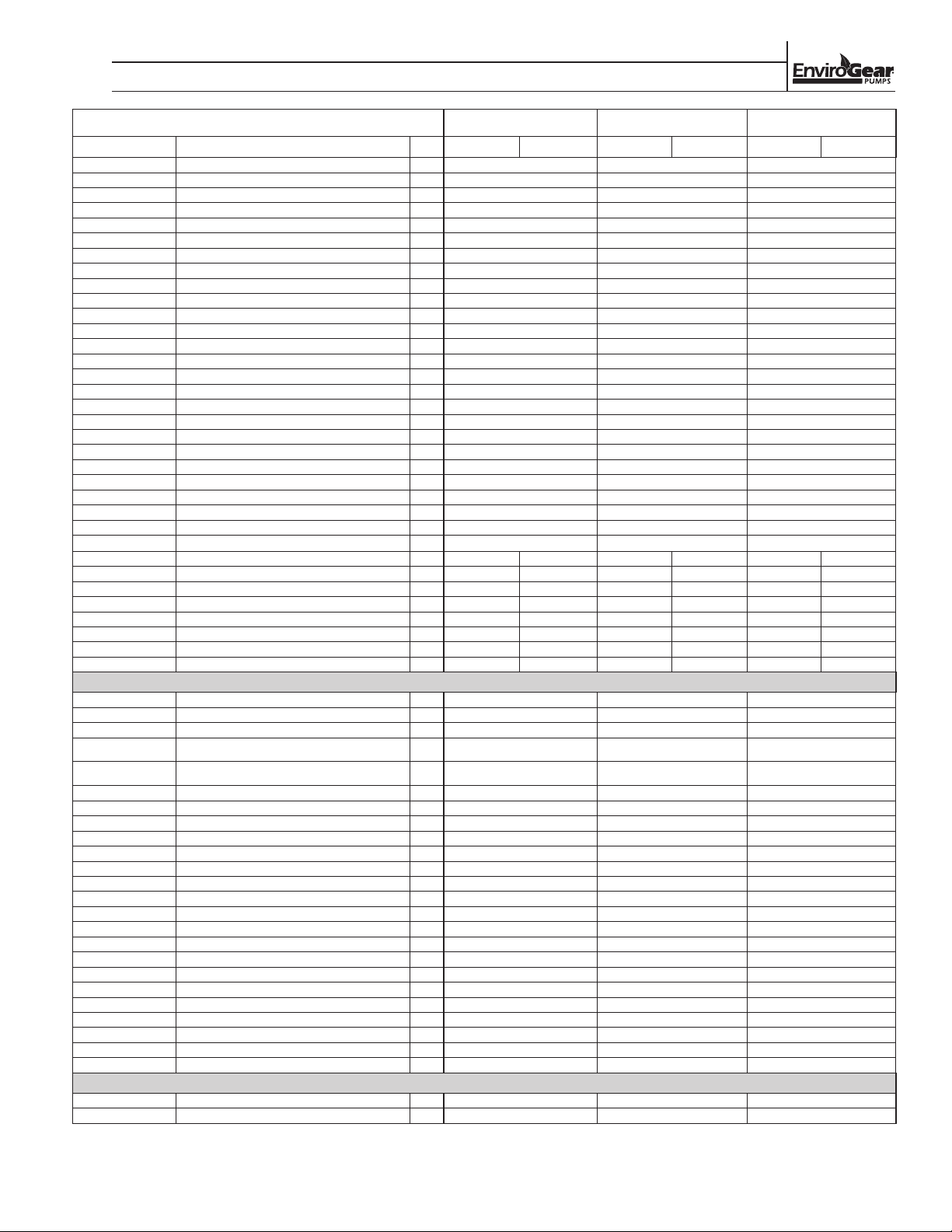
SECTION 6
EXPLODED VIEW & PARTS LISTING, CONT.
MODELS E1-133 & E1-222 CAST IRON CARBON STEEL STAINLESS STEEL
Item Description Qty.
203 Magnet Segment, South, NIB ** MS13 MS13 MS13
204 Sleeve 1 SL11 SL11 SL11
205 O-Ring, Viton, -173 Size 1 HW232 HW232 HW232
205 O-Ring, FEP-Encapsulated Viton, -173 Size 1 HW259 HW259 HW259
205 O-Ring, Kalrez, -173 Size 1 HW260 HW260 HW260
205 O-Ring, PFA-Encapsulated Silicon, -173 Size 1 HW261 HW261 HW261
206 O-Ring, Viton, -170 Size 1 HW231 HW231 HW231
206 O-Ring, FEP-Encapsulated Viton, -170 Size 1 HW256 HW256 HW256
206 O-Ring, Kalrez, -170 Size 1 HW257 HW257 HW257
206 O-Ring, PFA-Encapsulated Silicon, -170 Size 1 HW258 HW258 HW258
207 Thrust Bushing, TC 2 BU149 BU149 N/A
207 Thrust Bushings, Bronze 2 BU146 BU146 N/A
207 Thrust Bushing, CG 2 BU145 BU145 BU145
207 Thrust Bushing, ROC Carbon 2 BU147 BU147 BU147
207 Thrust Bushing, Cast Iron 2 BU148 BU148 N/A
208 Radial Bushing, TC 2 1330-2800-340 1330-2800-340 N/A
208 Radial Bushing, Bronze 2 1330-2800-320 1330-2800-320 N/A
208 Radial Bushing, CG 2 1330-2800-300 1330-2800-300 1330-2800-300
208 Radial Bushing, ROC Carbon 2 1330-2800-302 1330-2800-302 1330-2800-302
208 Radial Bushing, Cast Iron 2 1330-2800-114 1330-2800-114 N/A
209 Socket Head Cap Screw, 1/2"-13 x 2'' long 3 HW230 HW230 HW230
210 Bushing Carrier 1 BC3 BC3 BC1
211 O-Ring, Viton, -160 Size 2 HW233 HW233 HW233
211 O-Ring, FEP-Encapsulated Viton, -160 Size 2 HW253 HW253 HW253
211 O-Ring, Kalrez, -160 Size 2 HW254 HW254 HW254
211
301 Idler A/B 1
301 Idler high visc clearance, C/F 1 ID67 ID71 ID67 ID71 ID69 ID73
301 Idler high temp clearance, D/E 1 ID68 ID72 ID68 ID72 ID70 ID74
302 Radial Bushing, TC 1 1330-5800-340 2220-5800-340 1330-5800-340 2220-5800-340 N/A N/A
302 Radial Bushing, Bronze 1 1330-5801-320 2220-5801-320 1330-5801-320 2220-5801-320 N/A N/A
302 Radial Bushing, CG 1 1330-5801-300 2220-5801-300 1330-5801-300 2220-5801-300 1330-5801-300 2220-5801-300
302 Radial Bushing, ROC Carbon 1 1330-5801-302 2220-5801-302 1330-5801-302 2220-5801-302 1330-5801-302 2220-5801-302
302 Radial Bushing, Cast Iron 1 1330-5801-114 2220-5801-114 1330-5801-114 2220-5801-114 N/A N/A
O-Ring, PFA-Encapsulated Silicon, -160 Size
RELIEF VALVE ASSEMBLY
401 Valve Body 1 1330-7100-110 1330-7100-130 1330-7100-130
401 Valve Cover, SS (Not Shown) 2 1330-7101-250 1330-7101-250 1330-7101-250
402 Valve Poppet 1 1330-7400-110 1330-7400-110 1330-7400-110
403
403
403 Valve Spring, Large (Used with 200 psi valves) 1 1330-7602-250 1330-7602-250 1330-7602-250
404 O-Ring, Viton, -233 Size 2 HW262 HW262 HW262
404 O-Ring, FEP-Encapsulated Viton, -233 Size 2 HW265 HW265 HW265
404 O-Ring, Kalrez, -233 Size 2 HW263 HW263 HW263
404 O-Ring, PFA-Encapsulated Silicon, -233 Size 2 HW264 HW264 HW264
405 Screw, 3/8"-16 x .75" long 8 S01C375750WA2A2 S01C375750WA2A2 S01C375750WA2A1
406 Valve Spring Guide 1 1330-7500-250 1330-7500-250 1330-7500-250
407 O-Ring, Viton, -157 Size 1 HW266 HW266 HW266
407 O-Ring, FEP-Encapsulated Viton, -157 Size 1 HW269 HW269 HW269
407 O-Ring, Kalrez, -157 Size
407 O-Ring, PFA-Encapsulated Silicon, -157 Size
408 Valve Bonnet 1 1330-7201-110 1330-7201-130 1330-7201-150
409 Valve Lock Nut
410 Valve Adjustment Screw
411 O-Ring, Viton, -126 Size 1 HW270 HW270 HW270
411 O-Ring, FEP-Encapsulated Viton, -126 Size 1 HW273 HW273 HW273
411 O-Ring, Kalrez, -126 Size 1 HW271 HW271 HW271
411 O-Ring, PFA-Encapsulated Silicon, -126 Size 1 HW272 HW272 HW272
412 Valve Cap 1 1330-7301-110 1330-7301-110 1330-7301-150
605 1/4" NPT Thermocouple RTD Unit, NEMA 4 1 HW219 HW219 HW219
605
** Magnet quantities may vary depending on pump configuration
Valve Spring, Small (Used with 50, 130, and 200
psi valves)
Valve Spring, Medium (Used with 80, 130, and 200
psi valves)
1/4" NPT Thermocouple RTD Unit, NEMA 4X SS ATEX
E1-133 E1-222 E1-133 E1-222 E1-133 E1-222
2 HW255 HW255 HW255
1330-5100-121 2220-5100-121 1330-5100-121 2220-5100-121 1330-5100-176 2220-5100-121
1 1330-7600-250 1330-7600-250 1330-7600-250
1 1330-7601-250 1330-7601-250 1330-7601-250
1
1
1
1
HW267 HW267 HW267
HW268 HW268 HW268
1330-7710-255 1330-7710-255 1330-7710-255
1330-7700-255 1330-7700-255 1330-7700-255
OPTIONS
1
HW275 HW275
HW219
ENV-11000-E-04 45 ENVIROGEAR
Page 48

SECTION 9
TROUBLESHOOTING
Symptom or Problem: Pump is excessively noisy.
Problem Cause(s):
• Air in the inlet fluid stream
• Relief valve is opening
• Pump has decoupled
• Pump components are damaged or worn
• Pump is cavitating
• Discharge line is too restrictive
• Cooling path is plugged
• Ball bearings are worn or damaged
Symptom or Problem: Pump does not prime.
Problem Cause(s):
• Discharge line is too restrictive
• Suction lift is too great
• Pump is not wetted
• Air leak in the suction line
• Pump is running in the wrong direction
• Head is positioned incorrectly
• Cooling-path plugs are not installed
• Pump is locked up with hardened fluid or foreign
items
• Pump components are damaged or worn
• Pump has decoupled
• Inner magnets have weakened
• Cooling path is plugged
• Relief valve is stuck open
Symptom or Problem: Flow rate is too low.
Problem Cause(s):
• Head is positioned incorrectly
• Cooling-path plugs are not installed
• Discharge line is too restrictive
• Viscosity is lower than expected
• Air in the inlet fluid stream
• Pump is cavitating
• Relief valve is opening
• Pump components are damaged or worn
• Bypass or auxiliary line in the discharge piping is
open
• Cooling path is plugged
• Relief valve is stuck open
Symptom or Problem: Pump does not develop enough
pressure.
Problem Cause(s):
• Viscosity is lower than expected
• Air in the inlet fluid stream
• Pump is cavitating
• Relief valve is opening
• Pump components are damaged or worn
• Bypass or auxiliary line in the discharge piping is
open
• Head is positioned incorrectly
• Cooling-path plugs are not installed
• Cooling path is plugged
• Relief valve is stuck open
Symptom or Problem: Relief valve does not open.
Problem Cause(s):
• Pump is running in the wrong direction
• Relief valve is stuck closed
Symptom or Problem: Leakage from head/casing area.
Problem Cause(s):
• O-ring material is not compatible with pumped
fluid
• Sealing surfaces for the O-rings are damaged
• Bolt(s) are loose or missing
• O-ring is damaged or missing
Symptom or Problem: Leakage from casing/magnethousing area.
Problem Cause(s):
• O-ring material is not compatible with pumped
fluid
• Sealing surfaces for the O-rings are damaged
• Casing or magnet-housing mounting flanges are
cracked
• Bolt(s) are loose or missing
• O-ring is damaged or missing
ENVIROGEAR 46 ENV-11000-E-04
Page 49

SECTION X
TROUBLESHOOTING
Symptom or Problem: Leakage from head/valve-body
area.
Problem Cause(s):
• O-ring material is not compatible with pumped
fluid
• Sealing surfaces for the O-rings are damaged
• Bolt(s) are loose or missing
• O-ring is damaged or missing
Symptom or Problem: Leakage from drive-shaft area.
Problem Cause(s):
• Canister is damaged or leaking
Symptom or Problem: Excessive Vibration.
Problem Cause(s):
• Air in the inlet fluid stream
• Relief valve is opening
• Pump has decoupled
• Pump components are damaged or worn
• Pump is cavitating
• Ball bearings are worn or damaged
• Inner magnets have weakened
• Cooling-path is plugged
Symptom or Problem: Pump draws too much power.
Problem Cause(s):
• Pump components are damaged or worn
• Relief valve is stuck closed
• Ball bearings are worn or damaged
• Viscosity is higher than expected
ENV-11000-E-04 47 ENVIROGEAR
Page 50

SECTION X
NOTES
Page 51
SECTION 10
WARRANTY
Each and every product manufactured by EnviroGear® Pumps is built to meet the highest standards of quality.
Every pump is functionally tested to insure integrity of operation.
EnviroGear Pumps warrants that pumps, accessories and parts manufactured or supplied by it to be free from
defects in material and workmanship for a period of five (5) years from date of installation or six (6) years from
date of manufacture, whichever comes first. Failure due to normal wear, misapplication, or abuse is, of course,
excluded from this warranty.
Since the use of EnviroGear Pumps equipment is beyond our control, we cannot guarantee the suitability of
any pump or part for a particular application and EnviroGear shall not be liable for any consequential damage
or expense arising from the use or misuse of its products on any application. Responsibility is limited solely to
replacement or repair of defective EnviroGear products.
All decisions as to the cause of failure are the sole determination of EnviroGear Pumps.
Prior approval must be obtained from EnviroGear for return of any items for warranty consideration and must
be accompanied by the appropriate MSDS for the product(s) involved. A Return Goods Tag, obtained from an
authorized EnviroGear distributor, must be included with the items which must be shipped freight prepaid.
The foregoing warranty is exclusive and in lieu of all other warranties expressed or implied (whether written or
oral) including all implied warranties of merchantability and fitness for any particular purpose. No distributor or
other person is authorized to assume any liability or obligation for EnviroGear Pump Company other than expressly
provided herein.
PLEASE PRINT OR TYPE, AND EMAIL TO ENVIROGEAR
PUMP INFORMATION
Item # Serial #
Company Where Purchased
YOUR INFORMATION
Company Name
Industry
Name Title
Street Address
City State Postal Code Country
Telephone Fa x Email Web Address
Number of pumps in facility? Number of EnviroGear pumps?
Types of pumps in facility (check all that apply): Diaphragm
Centrifugal
Gear
Submersible
Lobe
Media being pumped?
How did you hear of Wilden Pump?
Other
Other
Trade Journal
Trade Show
Internet/Email
Distributor
ONCE COMPLETE, EMAIL TO
ENV-11000-E-04 49 ENVIROGEAR
Page 52

PSG
22069 Van Buren St., Grand Terrace, CA 92313-5607
P: +1 (909) 422-1731
www.maag.com
• F: +1 (909) 783-3440
envirogearpump.com
Where Innovation Flows
PSG® reserves the right to modify the information and illustrations contained in this document without prior notice. This is a non-contractual document. 04-2018
Authorized PSG Representative:
Copyrigh t ©2018, PS G®, A Dover Compa ny
REPLACES ENV11000E03
ENV11000E04
 Loading...