

Page 1

TM
EnviroCool
“The Fresh-Air Conditioning System”
“The natural choice for energy savings”
Installation Manual
Model EC-3040 Vertical
Read carefully all of this manual prior to installing the unit.
Model EC-4824 Horizontal
Page 2

System Design and Layout
T
T
story
or rooms that desire the lowest comfort
The room closest
Each QuietCool fan can only be installed in a room that has an attic above or adjacent to it, or has a
capable
performance.
1500 fan installed, and/or a QC-
rooms.
C
ool or a QuietCool fan in each room or to have the
ool to the fan go through each room that is to be cooled.
SIZING
most eectively in cooling each type home.
The type and size of home is the main factor that determines how much air should be moved through it
which give the necessary air exchanges per hour to provide sucient cooling.
Rules of thumb have been developed to arrive at satisfactory results for most conditions.
1. For newly or recently constructed homes that have tight envelopes and are insulated to recent high
2. For homes in cool coastal climates, the CFM’s can be reduced by 20%
3. For homes in hot desert climates, the CFM’s should be increased by 25%
4. For poorly insulated homes and homes that are not well sealed, the CFM’s should be increased by
5. For homes with high or vaulted ceilings, the CFM’s should be increased by 10%
6. The model number of the QuietCool fan designates its CFM performance. For example, a QuietCool
1. One EnviroCool unit is generally adequate for up to 1,750 square feet of oor space. Two EnviroCools
2. This general rule is based upon the premise that the rooms in the home that are in the pathway of
he rst step is to determine what size system, or how many EnviroCools and QuietCool fans would work
he climate zone is an important factor, and the type of construction of the home is also a consideration.
QUIETCOOL FAN SIZING RULES
standards, 300 CFM (cubic feet per minute) of fan performance should be added for each 100 square
feet of living space. For example, a 2000 sq. ft. home should have approximately 6000 CFM fan
performance.
20%.
QC-1500 has 1500 CFM performance, and a QC-4500 has 4500 CFM performance.
ENVIROCOOL SIZING RULES
are needed for homes up to 3,500 sq. ft., and add one additional EnviroCool for each additional 1,750
sq. ft. thereafter.
the moving air from the EnviroCool to each QuietCool fan will be cooled eectively. Those rooms not
in the pathway may not achieve satisfactory comfort levels. To overcome this problem, additional
EnviroCools can be added to these rooms if required.
(Example: Increase from 4 to 5 fans)
LAYOUT
Each home needs to be studied and planned so that the placement of QuietCool fans and EnviroCools
will achieve the optimum performance. The following rules will be helpful.
1. Each EnviroCool must be installed in an exterior wall. It should be on the lower oor of a multi-
home.
2. The best layout for the EnviroCool is to place it in the room
level temperatures and are as far removed as possible from the location of the fans.
to the EnviroCool will be coolest, and the rooms farthest from it will be the warmest.
3.
roof directly above it.
4. When QuietCool fans are mounted in an attic, it must be ascertained that the attic has (or is
of having) vents to the outside in the amount of one square foot for each 750 CFM of fan
5. In single story houses, the fan (or fans) should be located as far as possible from the EnviroCool
location. It is recommended that each bedroom and oce have a QC4500 installed in a master bath. In multi story houses, the fans should be placed in upper story
6. The fans should generally be placed near the center of each room, to allow cooling by drawing air
from the Enviro
7. The ideal arrangement is to have either an EnviroC
pathway of air moving from the EnviroC
ool, or from an open window when outside air is cool.
LAYOUT RULES
2
Page 3
System Sizing and Venting
g
Home Size (Sq. Ft.)EnviroCool QC 1500 Fan QC 4500 Fan *Total Fans Venting Required
1,000 - 1,500 1 4 0 4 8 sq. ft.
1,500 - 1,750 1 3 1 6 12 sq. ft.
1,800 - 2,500 2 4 1 7 14 sq. ft.
2,500 - 3,000 2 5 1 8 16 sq. ft.
3,000 - 3,500 2 6 1 9 18 sq. ft.
3,500 - 4,000 2 4 2 10 20 sq. ft.
4,000 - 4,500 3 5 2 11 22 sq. ft.
4,500 - 5,000 3 4 3 13 26 sq. ft.
5,000 - 5,500 3 5 3 14 28 sq. ft.
5,500 - 6,000 3 6 3 15 30 sq. ft.
* Total fans equal to one QC 1500 - ie. one QC4500 = QC 1500 fans.
Homes with vaulted ceilin
s in main area ad 1.25 percent to entire home sizei.e. 2,000 (sq. ft.) x 1.25 = 2,500 sq. ft.
Gable vent Dormer vent Eave vent Ridge vent Soffet vent
Average size 12" x 19.5"
Venting Sq. Ft. 1.20 0.70 0.35
14" x 8"
3.5" x 22.5"
various various
various various
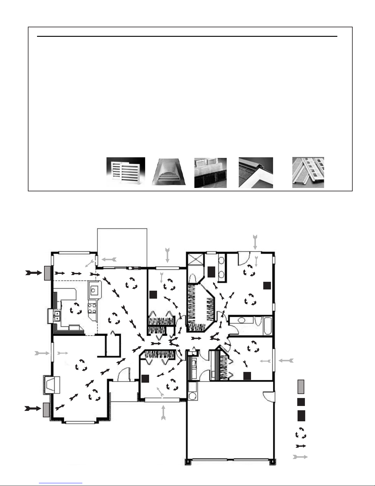
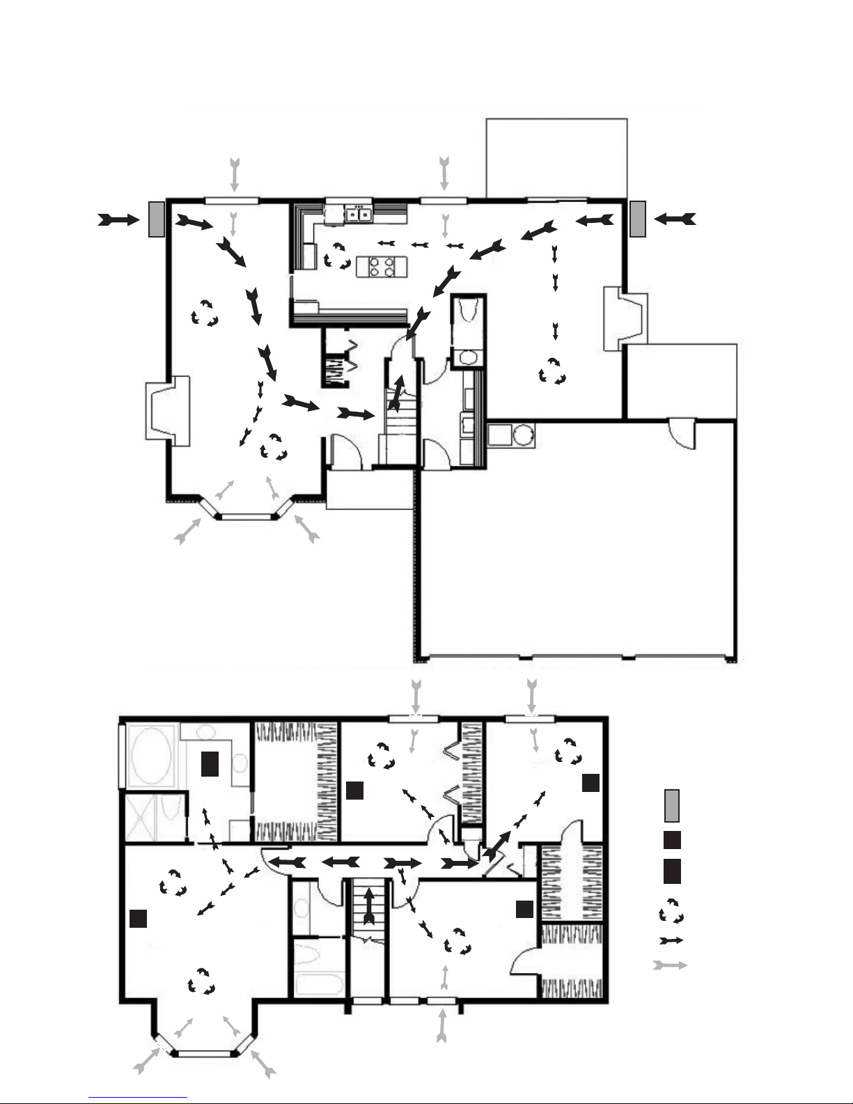
THESE SAMPLE FLOOR PLANS SHOW EXAMPLES OF PROPER PLACEMENTS.
Single Story Example
(2,047 sq. ft)
Patio
Nook
EC
Bedroom
QC
Family Room
Bath
QC
G
Master
Bedroom
QC
Kitchen
Dining Room
EC
Living Room
Bedroom
QC
Bath
Bedroom
Legend
QC
EnviroCool
EC
QC
QC 1500 Fan
QC
QC 4500 Fan
G
Garage
Air movemet
Air direction
(when used with open windows)
3
QC fan air intake
Page 4
EC
Two Story Example
(2,489 sq. ft)
First Floor Plan
Patio
EC
Dining Room
Living Room
Kitchen
Family Room
UP
Patio
Garage
Second Floor Plan
QC
G
Bath
QC
Master
Bedroom
Bath
QC
Bedroom
4
Bedroom
Bedroom
QC
QC
Legend
EnviroCool
EC
QC
QC 1500 Fan
QC
QC 4500 Fan
G
Air movemet
Air direction
(when used with open windows)
QC fan air intake
Page 5
EnviroCool Installation Instructions
Safety Rules
!
1. Read instructions carefully.
2. Electrical hook up should be done by a qualied electrician. All electrical wiring must conform to
local code standards.
!
WARNING:
To reduce the risk of electric shock, always disconnect power and unplug pump motorbefore
installation or performing maintenance Make sure EnviroCool cabinet is properly grounded to a
suitable ground connection for maximum safety.
!
Avoid Backdrafts
Care should be taken to avoid backdrafting combustion appliances that are installed in the conditioned
space. It is strongly recommended that combustion appliances NOT be installed in such a manner that
they use room air for for combustion. The whole house fans is capable of pulling large quantities of air
from the home and particulary if not enough windows are open, may easily backdraft a water heater
located inside a louvered closet door
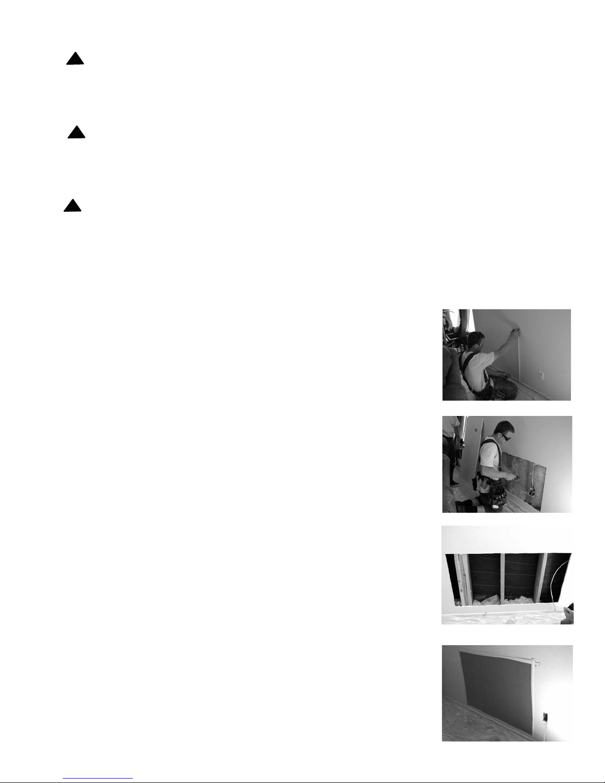
Select a tentative location. You should consider all the clearances that you
will need by observing both inside and outside before making a nal
selection. Make sure from the outside wall that the unit is high enough that
the bottom will not touch the ground and the top won’t stick above the
window (if placed under window). Usually 36 inches is needed from
window to ground level for horizontal.
CLEARANCES around “ROUGH OPENING”
sides top bottom
Exterior 2 ½” 4” 6”
Interior 1” 1” 1”
Make a cutout template out of cardboard using the ‘rough opening’
1.
dimensions.
After making sure you have the clearances needed place the cutout
2.
template on the inside wall and draw the template outline. For the vertical
model, the template should be centered on a stud. For the horizontal
model, it should be centered between the king studs if under a window.
The template should be at least 2” above the baseboard to allow for the
interior grill.
Cutout the drywall per the template using a drywall handsaw. Do not saw
3.
through any studs.
Remove the drywall cutout and any insulation inside the cavity.
4.
Transfer the location to the outside by drilling 3/8” holes at the 4 corners
5.
through the outside wall from inside.
Temporarily tape plastic or cardboard over the inside opening to keep out
6.
dust & debris while cutting the opening in the outside wall.
5
Page 6
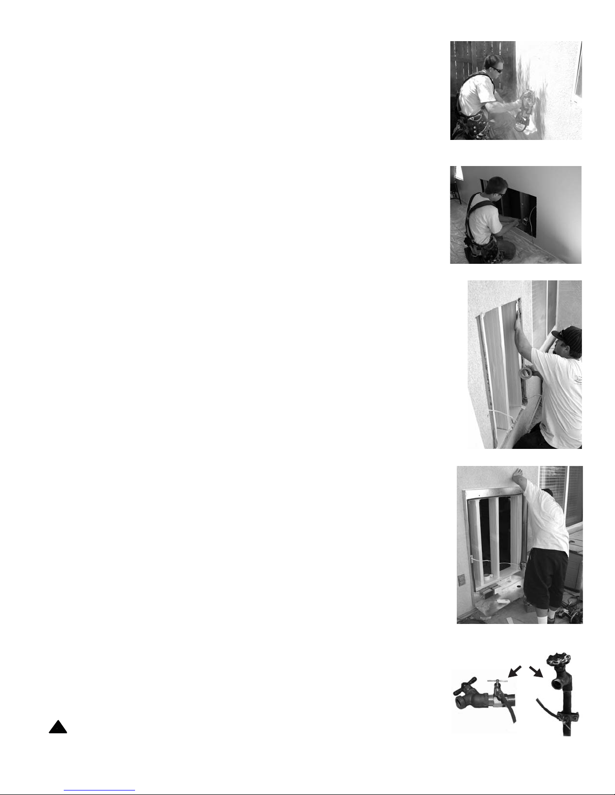
Place the template on the outside wall and draw the outline.
g
7.
Skilsaw (circular saw) to the outline. A diamond saw blade works best.
8.
Set the blade depth to the wall thickness plus approx. ¼”.
If electric wire is encountered in the opening, turn o the power to that
9.
circuit and then cut the wire in two at the center of the opening. Chisel
a notch in the studs at the sides of the wire opening to bring the wire to the
outside, so that the wire is ush with the face of the studs or create new
outlets on each side of unit and run new wire to re-feed circuit.
10.
If no electric wire is found in the opening, bring a wire from the nearest wall
receptacle on the inside wall into the opening and route to the outside by
chiseling a notch in the stud as described above.
Cut and screw in place ¼” coroplast blocks top and bottom. The coroplast
11.
should be wide enough to cover the opening as well as the thickness of the
inside drywall edge plus the outside wall edge. The bottom coroplast
blocks should slope very slightly downhill toward the outside. Cover the
sides of the opening with coroplast and tape the studs with duct tape so
that no bare wood is visible. Apply duct tape completely around the
opening on both the inside and outside. Install the duct tape by allowing ½
of the width of the tape to be on the coroplast in the opening and the other
half of the tape is then folded over onto the inside and outside walls.
Locate and fasten the main frame to the outer wall using (3) #10 x 2” screws
12.
on each side that will go through the exterior wall and into each side stud.
Where electric wire is protruding, cut a notch in the mainframe using tin
snips to eliminate contact with the mainframe. Prior to fastening the
mainframe to the wall, run a large bead of window and door caulk around
the top and sides of the back of the mainframe to obtain a good seal to the
exterior wall. After fastening the mainframe in place, apply an additional
small bead of caulk around the top and sides of the mainframe to wall joint.
13.
Make electrical connections at inside of mainframe at the junction box so
that the plug receptacle is hot. Then turn power back on.
Bring ¼” poly waterline from nearest outside source such as a hose bib, and
14.
connect to bottom left corner of mainframe. Fasten poly pipe to wall with
clips to maintain a neat, straight installation so that there are no places for
poly pipe to become snagged and damaged.
IMPORTANT!! – DO NOT CONNECT TO SOFTWATER.
!
Soft water will dama
e the media.
or
6
Page 7
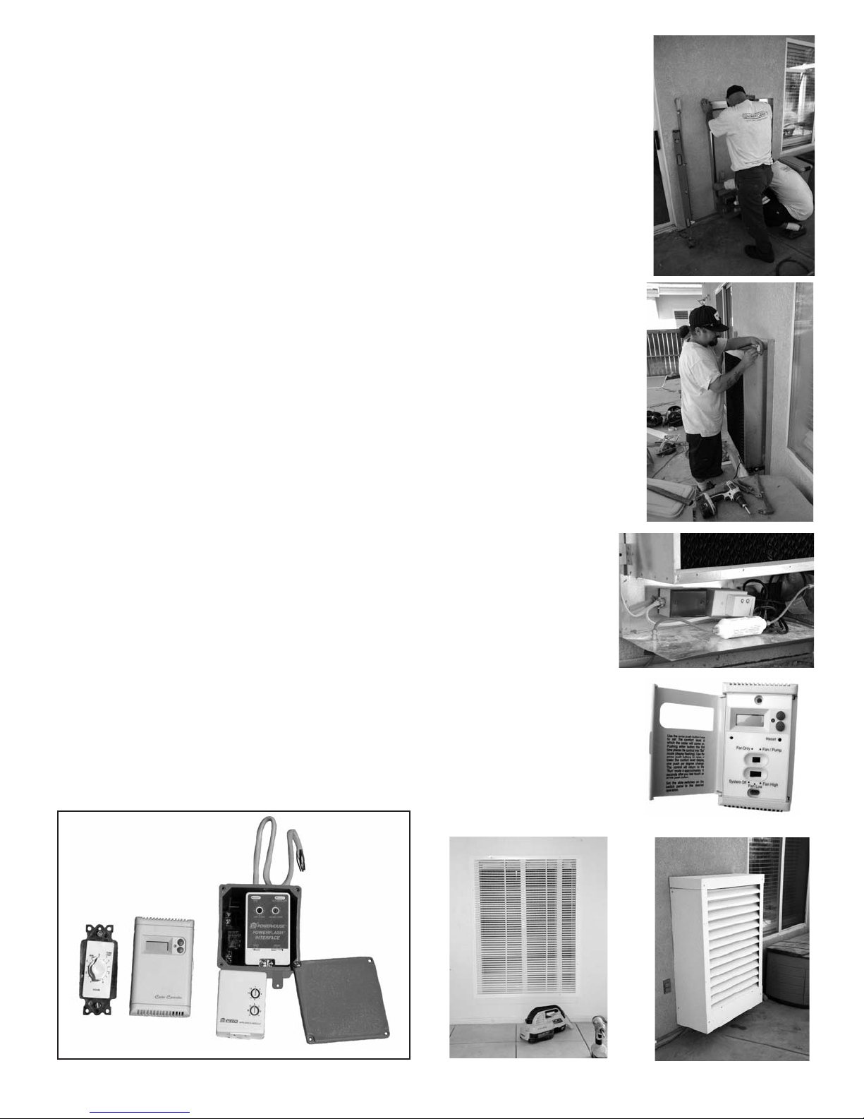
With water supply turned on, check for correct operation of oat valve.
15.
Water should ll pan to approx. ¼” to ¾” below top of plastic overow tube.
16.
Install media holder by attaching to mainframe with (4) #10 x 5/8 sheet
metal screws.
17.
Attach 5/8” poly water tube to water pump and place water pump in right
rear corner of water pan. Secure tube to side of media holder with wire ties
through adhesive anchor pads.
Check for proper ow of water through the media and back into water pan
18.
by temporarily plugging pump into receptacle. Allow to run for several
minutes and make sure all water is returning into the water pan and that
there is no water dripping anywhere.
Unplug pump from receptacle, plug Appliance Module into receptacle
19.
and then plug pump into bottom of Appliance Module. This remote
module will receive it’s on and o signals from the remote mounted
thermostat and control box.
Install the exterior housing. Hold in place, with (2) #10 x 5/8 self drilling
20.
sheet metal screws on each side.
Install interior grill with white screws provided.
21.
Install the thermostat in the wall above the fan timer and install the
22.
control box in the attic as per wiring diagram.
System Controls Kit
Powerash
& Relay Box
Timer
Thermostat
Remote module
7
Page 8
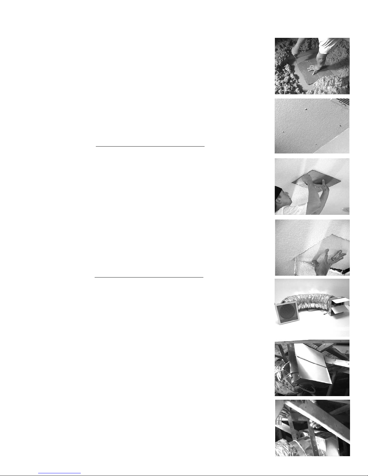
QuietCool fan installation instructions
1.
Now that you have determined in which areas you would like to install your
QuietCool fans, it’s time to go into your attic to mark the exact location for each
install from above.
When you nd a location, move the insulation away to get a clear view. Make
2.
sure the template ts between the framing, and there are no other
obstructions in your chosen location. If there is a reason you can not use the
exact spot, nd a location in the area that does work. Place the template on
the spot and mark it by making a hole at each corner with a screwdriver.
Repeat these steps at each location
3.
Once all locations are marked, move the insulation away and return below to
the house. It’s now time to cut the holes at each air intake location.
Place the cut-out template at each location making sure you have 2 inches of
4.
clearance all the way around it. The grill that will be installed later is larger than
the template. While holding the template in place, mark around it with a
pencil. Using a drywall saw, or similar device, cut out the hole.
Repeat these steps at each location
Open and unpack each QuietCool fans. Make sure all parts are present. Most of
5.
the system comes pre-assembled. The main assembly should be put up in the
attic through the crawl hole and moved into position near the ceiling cutout
hole.
It’s now time to hang the motor heads from the rafters. Your goal is to hang
6.
the motor head as far from the hole in the ceiling as possible, while making
sure the ceiling box and duct will easily reach the hole.
Using the metal strapping attached to the motor head assembly, and the gray
7.
deck screws provided, hang the motor head from the rafters. Make sure the
motor head is fairly level side to side. Again, make sure the ducting will reach
the ceiling cut out with a little slack. You will need to secure the ducting later
in these instructions.
8
Page 9
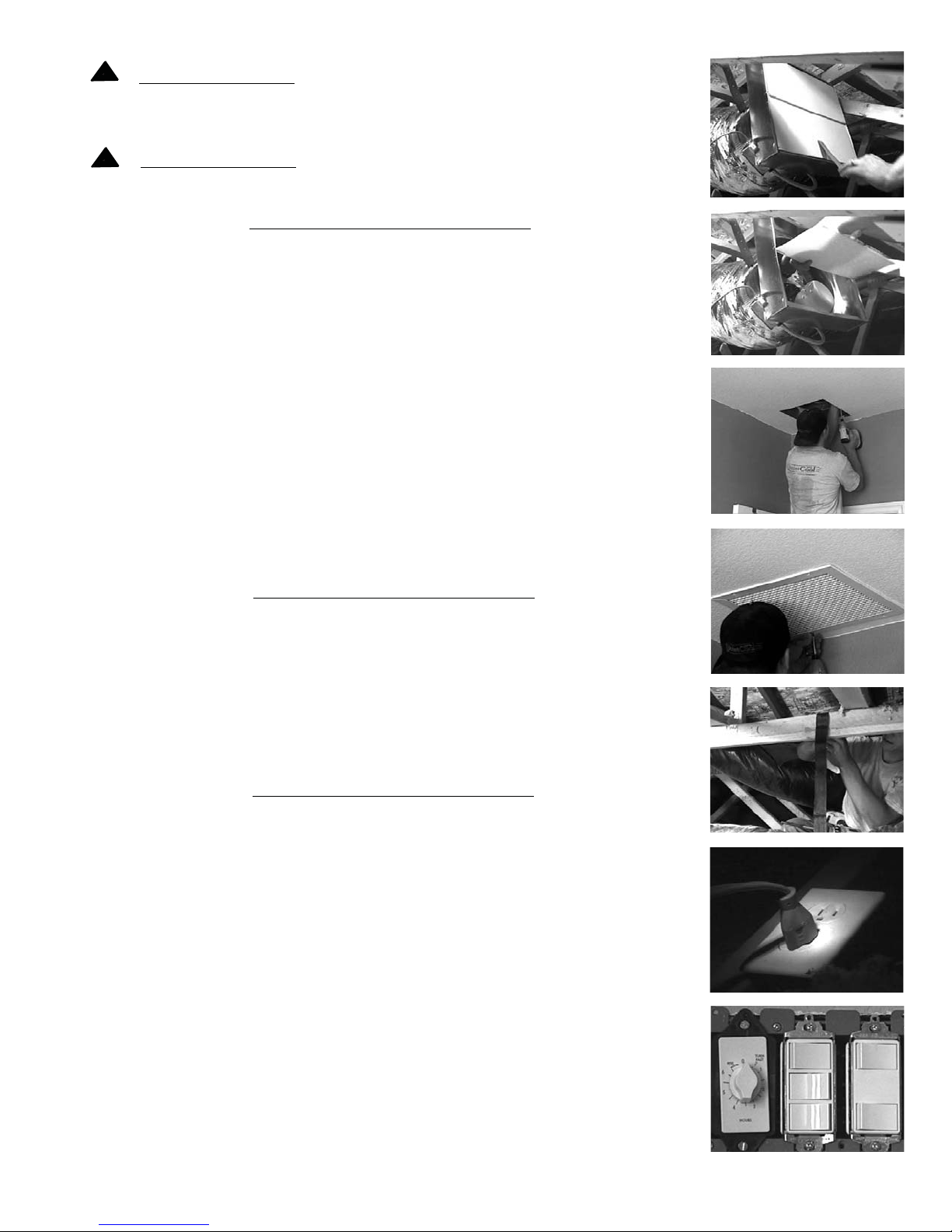
8.
T
T
!
VERY IMPORTANT!
dampers. Make sure the dampers will open and close easily and without
obstruction.
Remove the shipping tape from the back draft
9.
important to system operation.
Once all of the QuietCool fans are hung, it’s time to go below and install the
10.
ceiling box and ceiling grill at each intake location.
Look through the hole and make sure there are no kinks or twists in the
11.
ducting. Pull the ceiling box down through the hole in the ceiling. While
holding it in place, install a 1-3/8” drywall screw through the drywall into the
ange of the ceiling box on each side to temporarily hold the box in place.
Remove ceiling grill and screws from its packaging. Center the grill over the
ceiling box. Install the grill with the white screws provided by screwing
through the ange of the ceiling box. Some ceiling surfaces are uneven and
may cause a small gap to be present. This can easily be caulked later if
excessive.
VERY IMPORTANT!
!
Make sure the fan blade spins freely. This is very
Repeat these steps at each location
Repeat these steps at each location
12.
Return to the attic and go to each location. Using the nylon straps and the pan
head screws provided, support the duct to the framing. Make sure the motor
head is still level and the dampers still close naturally. This will stabilize the
entire assembly. Replace any insulation that was removed.
Repeat these steps at each location
13.
he installation is now complete except for the electrical work necessary to
make them operate. The electrical wiring for the fan requires a 120 volt three
prong outlet within 6 feet of the motor head in the attic.
14.
he outlet should be wired to and controlled by a two-gang or three-gang box
installed in the hallway wall with a timer and switch for each fan.
9
Page 10
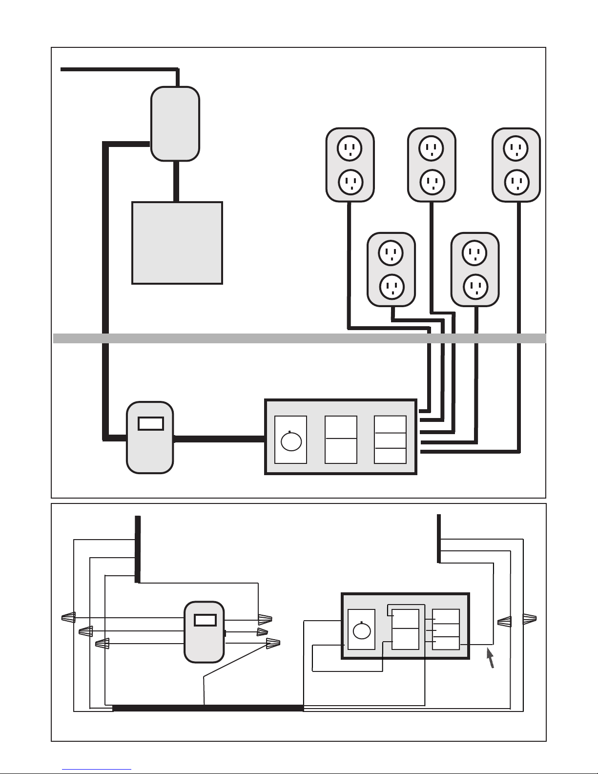
Power Source
2 wire with ground
Romex cable
Wiring Diagram
3 wire with ground
Romex cable
In from Junction Box
3 wire with ground
Romex cable
Junction
Box
3 wire with ground
Romex cable
QuietCool
Control Box
One Gang Box
QC1500 Fan Receptacles
QC4500 Fan Receptacles
Attic Side
In Home Side
Fan Timer & Switches
One Gang Box
Black
White
Green
Green
White
Black
72
Cooler
Control
From Thermostat
to Switch Box
3 wire with ground
Romex cable
3 wire with ground
Romex cable
Black
White
Green
Cooler
Control
72
Red
Timer
Three Gang Box
Wiring Detail
Red
Orange
Red
Yellow
Cap o
Black
(Line)
(Load)
Black
2 Switch
3 Switch
2 wire with ground
Romex cable
Fan Timer & Switches
Red
Timer
2 Switch
To Each Fan
2 wire with ground
Romex cable
White
Black
3 Switch
Red
Typical wiring for
each fan receptical
Black
installed
Green
White
Green
3 wire with ground
Romex cable
10
Page 11
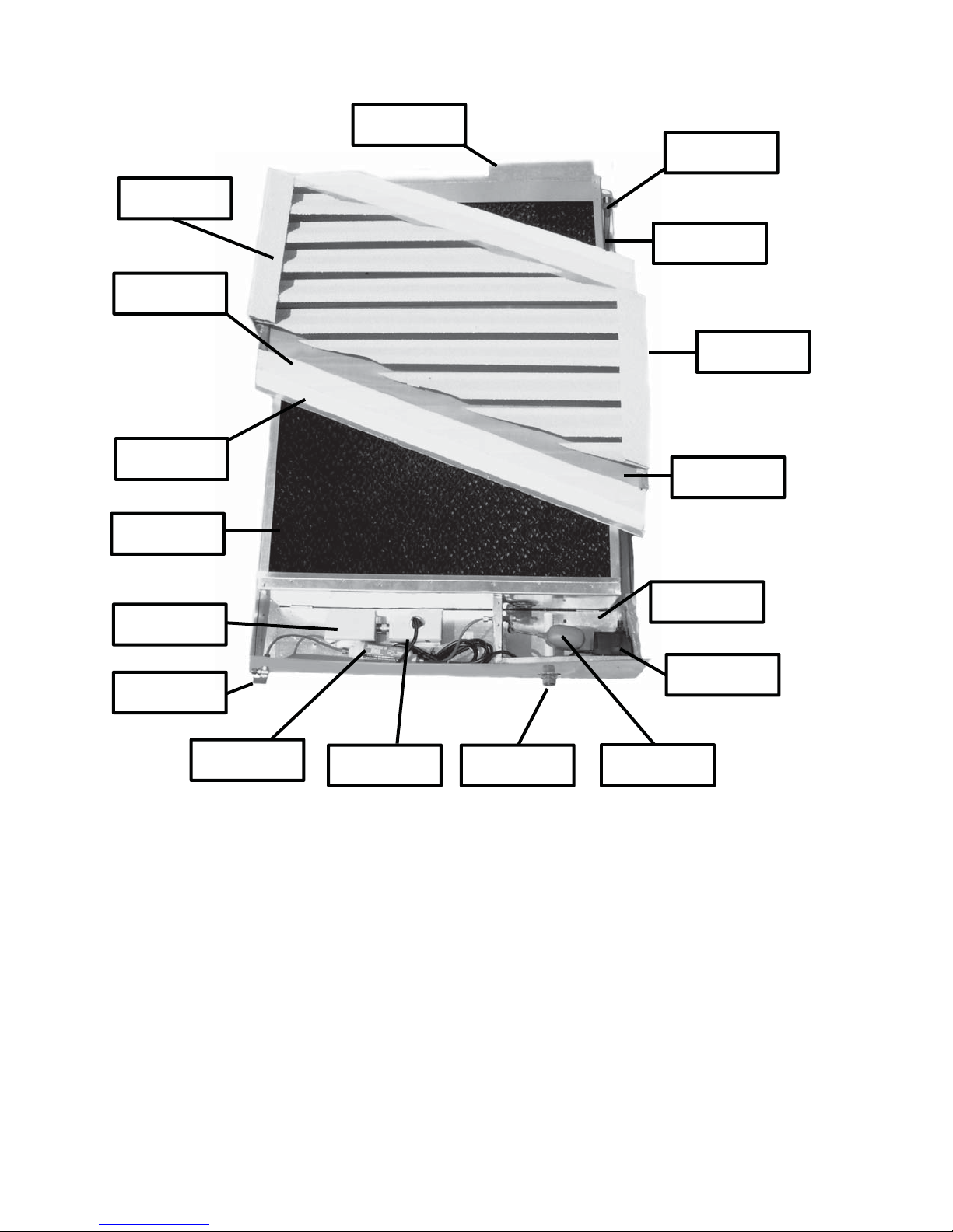
EnviroCool System Components Detail
Splash Guard
Exterior Cover
Insulated
Dampers
Winterizing
Insulation Board
Water
Distributor Pipe
Water
Feed Tube
Interior Grill
(not shown)
Insect Screen
Rigid
Cooling Media
Electrical
Connection Box
Water Shut Off
Water Filter
Parts List
Interior Grill (not shown)
Exterior Cover
Insulated Dampers
Winterizing Insulation Board
Rigid Cooling Media Replacement Unit
Water Shut O Valve
Connection Box
Connection Box Cover
Water Filter
Overow Outlet
Water Pump
Float and Valve Assembly
Water Reservoir
Insect Screen
Water Feed Tube
Water Distributor Pipe
Splash Guard
Remote Module
Remote module
Power Connection
Overflow Outlet
EC 3040 Vertical
EC-14005
EC-50080V
EC-60050-V
EC-60060-V
EC-60020-V
AC-45100
AC-21000
AC-21020
EC-20020
EC-21000
EC-20025
EC-20010
EC-13200
EC-60040-V
EC-50035-V
EC-60030-V
EC-13015-V
IT-31010
Water Reservoir
Float & Valve
Water Pump
(EC-3040 shown)
EC 4824 Horizontal
EC-14000
EC-50080H
EC-60050-H
EC-60060-H
EC-60020-H
AC-45100
AC-21000
AC-21020
EC-20020
EC-21000
EC-20025
EC-20010
EC-13200
EC-60040-H
EC-50035-H
EC-60030-H
EC-13015-H
IT-31010
11
Page 12
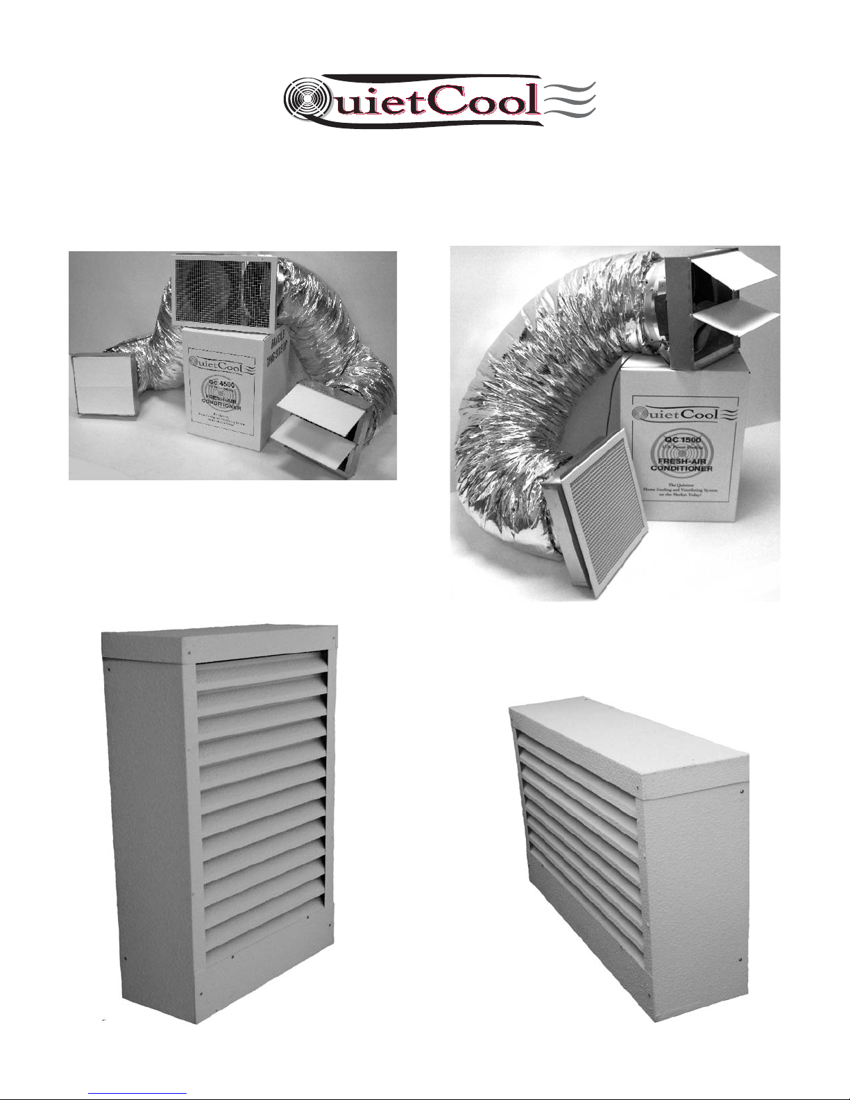
Manufactured by
“The Whisper Quiet Whole House Fan System”
QC 1500 fan
EC-3040 vertical
EnviroCool
QC 4500 fan
EC-4824 horizontal
EnviroCool
Rev. 9.08
12
 Loading...